Product Manual
Page 2
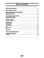
TABLE OF CONTENTS UNIT SPECIFICATIONS 2 PART IDENTIFICATION 3 IMPORTANT SAFETY INFORMATION Electrical Specifications 3 Energy Saving Tips 4 OPERATING INSTRUCTIONS Internal Safety Features 4 Draining Excess Water 5 INSTALLATION 5 Window Kit Installation 6 OPERATION Remote Control 7 LCD Display 7 Air Conditioning 8 Auto 8 Dehumidifier 9 Fan 9 Auto Timer 11 Clock Set 11 CARE AND MAINTENANCE 12 TROUBLESHOOTING 13 Warranty 14 1
TABLE OF CONTENTS UNIT SPECIFICATIONS 2 PART IDENTIFICATION 3 IMPORTANT SAFETY INFORMATION Electrical Specifications 3 Energy Saving Tips 4 OPERATING INSTRUCTIONS Internal Safety Features 4 Draining Excess Water 5 INSTALLATION 5 Window Kit Installation 6 OPERATION Remote Control 7 LCD Display 7 Air Conditioning 8 Auto 8 Dehumidifier 9 Fan 9 Auto Timer 11 Clock Set 11 CARE AND MAINTENANCE 12 TROUBLESHOOTING 13 Warranty 14 1
Product Manual
Page 4
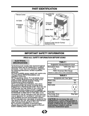
... servicing. DO NOT USE PLUG ADAPTERS OR EXTENSION CORDS WITH THIS UNIT. TABLE 1 Suggested Individual Branch Circuit Nameplate Amps 11.5 *AWG Wire Size 14 AWG- Remote Control Air Outlet Emergency On/Off Switch PART IDENTIFICATION Evaporator Air Intake Evaporator Air Intake Cable Hook Drainage Pipe Power Supply Continuous drain hole (for...
... servicing. DO NOT USE PLUG ADAPTERS OR EXTENSION CORDS WITH THIS UNIT. TABLE 1 Suggested Individual Branch Circuit Nameplate Amps 11.5 *AWG Wire Size 14 AWG- Remote Control Air Outlet Emergency On/Off Switch PART IDENTIFICATION Evaporator Air Intake Evaporator Air Intake Cable Hook Drainage Pipe Power Supply Continuous drain hole (for...
Product Manual
Page 8
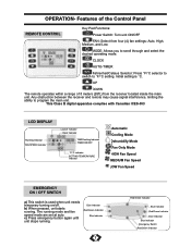
OPERATION- Any obstruction between the receiver and remote may cause signal interference, limiting the ability to scroll through and select the desired operating mode. The running . b) When pressed, unit starts running mode and ... Indicator Blue Indicator Emergency Switch Red/Green Indicator Initial setting is used when unit needs temporary turning on/off. UP DOWN The remote operates within a range of the Control Panel REMOTE CONTROL Key Pad Functions: Power Switch: Turn unit ON/OFF FAN: Select from the receiver located inside the main unit. MODE...
OPERATION- Any obstruction between the receiver and remote may cause signal interference, limiting the ability to scroll through and select the desired operating mode. The running . b) When pressed, unit starts running mode and ... Indicator Blue Indicator Emergency Switch Red/Green Indicator Initial setting is used when unit needs temporary turning on/off. UP DOWN The remote operates within a range of the Control Panel REMOTE CONTROL Key Pad Functions: Power Switch: Turn unit ON/OFF FAN: Select from the receiver located inside the main unit. MODE...


