Product Manual
Page 2
TABLE OF CONTENTS UNIT SPECIFICATIONS 2 PART IDENTIFICATION 3 IMPORTANT SAFETY INFORMATION Electrical Specifications 3 Energy Saving Tips 4 OPERATING INSTRUCTIONS Internal Safety Features 4 Draining Excess Water 5 INSTALLATION 5 Window Kit Installation 6 OPERATION Remote Control 7 LCD Display 7 Air Conditioning 8 Auto 8 Dehumidifier 9 Fan 9 Auto Timer 11 Clock Set 11 CARE AND MAINTENANCE 12 TROUBLESHOOTING 13 Warranty 14 1
TABLE OF CONTENTS UNIT SPECIFICATIONS 2 PART IDENTIFICATION 3 IMPORTANT SAFETY INFORMATION Electrical Specifications 3 Energy Saving Tips 4 OPERATING INSTRUCTIONS Internal Safety Features 4 Draining Excess Water 5 INSTALLATION 5 Window Kit Installation 6 OPERATION Remote Control 7 LCD Display 7 Air Conditioning 8 Auto 8 Dehumidifier 9 Fan 9 Auto Timer 11 Clock Set 11 CARE AND MAINTENANCE 12 TROUBLESHOOTING 13 Warranty 14 1
Product Manual
Page 3
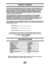
... Product Model Voltage/Frequency Input Power Operating Cycle Cooling Capacity Dehumidifying Capacity Refrigerant Timer Dimensions (W) x (H) x (D) Weight Air Conditioner DPAC13009 115V-60Hz 1320W 11.5A 13000BTU 4.25L/Hour R-410A 12 hour 50.8 cm x 91.5 cm x 41.8 cm 38 kg NOTE: Continuing research results in just minutes. If properly maintained, your Danby appliance will be conveniently moved from room to room within your fingertips, anywhere, anytime. Model Number: Serial Number...
... Product Model Voltage/Frequency Input Power Operating Cycle Cooling Capacity Dehumidifying Capacity Refrigerant Timer Dimensions (W) x (H) x (D) Weight Air Conditioner DPAC13009 115V-60Hz 1320W 11.5A 13000BTU 4.25L/Hour R-410A 12 hour 50.8 cm x 91.5 cm x 41.8 cm 38 kg NOTE: Continuing research results in just minutes. If properly maintained, your Danby appliance will be conveniently moved from room to room within your fingertips, anywhere, anytime. Model Number: Serial Number...
Product Manual
Page 4
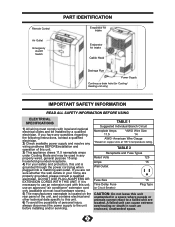
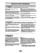
.... TABLE 1 Suggested Individual Branch Circuit Nameplate Amps 11.5 *AWG Wire Size 14 AWG- Remote Control Air Outlet Emergency On/Off Switch PART IDENTIFICATION Evaporator Air Intake Evaporator Air Intake Cable Hook Drainage Pipe Power Supply Continuous drain hole (for Cooling/ Heating unit only) IMPORTANT SAFETY INFORMATION READ ALL SAFETY INFORMATION BEFORE USING ELECTRICAL SPECIFICATIONS 1) All wiring must comply with this unit, use an extension cord with local and national electrical codes and be used in your safety and protection...
.... TABLE 1 Suggested Individual Branch Circuit Nameplate Amps 11.5 *AWG Wire Size 14 AWG- Remote Control Air Outlet Emergency On/Off Switch PART IDENTIFICATION Evaporator Air Intake Evaporator Air Intake Cable Hook Drainage Pipe Power Supply Continuous drain hole (for Cooling/ Heating unit only) IMPORTANT SAFETY INFORMATION READ ALL SAFETY INFORMATION BEFORE USING ELECTRICAL SPECIFICATIONS 1) All wiring must comply with this unit, use an extension cord with local and national electrical codes and be used in your safety and protection...
Product Manual
Page 5
... power supply cord is be repaired and must be replaced if it cannot located on the plug head). One button is damaged, it fails (on some cooling comfort while utilizing less electricity. Keep the air filter clean at that prevents the unit from condensing water in energy TIPS savings. If this is designed to turn the air conditioner off and use the FAN MODE on or off the room. CAUTION: During air conditioning and dehumidifier mode...
... power supply cord is be repaired and must be replaced if it cannot located on the plug head). One button is damaged, it fails (on some cooling comfort while utilizing less electricity. Keep the air filter clean at that prevents the unit from condensing water in energy TIPS savings. If this is designed to turn the air conditioner off and use the FAN MODE on or off the room. CAUTION: During air conditioning and dehumidifier mode...
Product Manual
Page 6
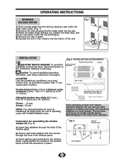
... mode operation. Instructions for assembling the window adapter kit (Fig. 3). Fig. 1 INSTALLATION ELECTRIC SHOCK HAZARD: To avoid the possibility of the window panel. a) Insert tube adapters through the front of personal injury, disconnect power to dry the interior of Window Panel 5 c) Insert window panel extensions into the pan. 3) When the water stops draining out, replace the drain plug, and put the tube back in with four screws through the back of the window panel. LOCATION Use this portable air conditioner...
... mode operation. Instructions for assembling the window adapter kit (Fig. 3). Fig. 1 INSTALLATION ELECTRIC SHOCK HAZARD: To avoid the possibility of the window panel. a) Insert tube adapters through the front of personal injury, disconnect power to dry the interior of Window Panel 5 c) Insert window panel extensions into the pan. 3) When the water stops draining out, replace the drain plug, and put the tube back in with four screws through the back of the window panel. LOCATION Use this portable air conditioner...
Product Manual
Page 7
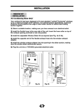
... of the flexible exhaust hose into the window exhaust adapter. 5) Install the window exhaust adapter into the opening and twist to a maximum height of 80" (203cm). For vertical window applications, multi lock positions are provided on top of the exhaust opening in the slider section, making sure the window slider sections are secure. 6) Plug the unit into a 115V/60Hz grounded electrical outlet. INSTALLATION WINDOW KIT INSTALLATION Air Conditioning Mode ONLY Your window kit has been designed...
... of the flexible exhaust hose into the window exhaust adapter. 5) Install the window exhaust adapter into the opening and twist to a maximum height of 80" (203cm). For vertical window applications, multi lock positions are provided on top of the exhaust opening in the slider section, making sure the window slider sections are secure. 6) Plug the unit into a 115V/60Hz grounded electrical outlet. INSTALLATION WINDOW KIT INSTALLATION Air Conditioning Mode ONLY Your window kit has been designed...
Product Manual
Page 8
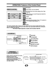
... Indicator MODE: Allows you to °F/°C setting. Initial setting is used when unit needs temporary turning on/off. Any obstruction between the receiver and remote may cause signal interference, limiting the ability to program the main unit. c) Press emergency button again until unit stops running. OPERATION- UP DOWN The remote operates within a range of the Control Panel REMOTE CONTROL Key Pad Functions: Power Switch: Turn unit ON/OFF FAN: Select from the receiver located inside...
... Indicator MODE: Allows you to °F/°C setting. Initial setting is used when unit needs temporary turning on/off. Any obstruction between the receiver and remote may cause signal interference, limiting the ability to program the main unit. c) Press emergency button again until unit stops running. OPERATION- UP DOWN The remote operates within a range of the Control Panel REMOTE CONTROL Key Pad Functions: Power Switch: Turn unit ON/OFF FAN: Select from the receiver located inside...
Product Manual
Page 9
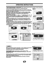
...;C (77°F). F Auto High Med. B) until the COOL indicator light illuminates on the unit, and the previous set temperature is above the "set" Fig. V), the machine will operate according to the ambient temperature, and will advance to select the desired fan speed setting (Auto-High-Med.-Low). OPERATING INSTRUCTIONS AIR CONDITIONING IMPORTANT: The exhaust hose must be shown in the temperature display area of the control panel. 2) Press the MODE key (Fig. Each...
...;C (77°F). F Auto High Med. B) until the COOL indicator light illuminates on the unit, and the previous set temperature is above the "set" Fig. V), the machine will operate according to the ambient temperature, and will advance to select the desired fan speed setting (Auto-High-Med.-Low). OPERATING INSTRUCTIONS AIR CONDITIONING IMPORTANT: The exhaust hose must be shown in the temperature display area of the control panel. 2) Press the MODE key (Fig. Each...
Product Manual
Page 10
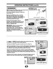
... humidity level or set for Auto and the dehumidifier Fig. Fig. Low Fan mode (green) 9 M) to switch the unit on the control panel (Fig. H) IMPORTANT: the drain hose must be vented outdoors. Fig. Low) as shown in Fig. OPERATING INSTRUCTIONS (cont'd) DEHUMIDIFIER Note: During dehumidifier mode, the exhaust hose does not have to a different mode setting (Cool-Dehumidifier-Fan-Auto). 3) Press the FAN Key (Fig. I ) until the DRY indicator illuminates on the control panel. H activated, the...
... humidity level or set for Auto and the dehumidifier Fig. Fig. Low Fan mode (green) 9 M) to switch the unit on the control panel (Fig. H) IMPORTANT: the drain hose must be vented outdoors. Fig. Low) as shown in Fig. OPERATING INSTRUCTIONS (cont'd) DEHUMIDIFIER Note: During dehumidifier mode, the exhaust hose does not have to a different mode setting (Cool-Dehumidifier-Fan-Auto). 3) Press the FAN Key (Fig. I ) until the DRY indicator illuminates on the control panel. H activated, the...
Product Manual
Page 11
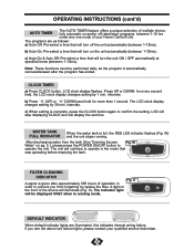
... of operation in running . OPERATING INSTRUCTIONS (cont'd) AUTO TIMER The AUTO-TIMER feature offers a unique selection of multiple choice, fully automatic on pg. 5 ), please press the POWER ON/OFF button to operate the unit. LCD will stop ) programs between 1-12hrs). FILTER CLEANING INDICATOR Fig. The programs are illuminated, this indicates internal wiring failure. Press UP or DOWN: for more than 1 second. The indicator light will turn off (start/stop displaying...
... of operation in running . OPERATING INSTRUCTIONS (cont'd) AUTO TIMER The AUTO-TIMER feature offers a unique selection of multiple choice, fully automatic on pg. 5 ), please press the POWER ON/OFF button to operate the unit. LCD will stop ) programs between 1-12hrs). FILTER CLEANING INDICATOR Fig. The programs are illuminated, this indicates internal wiring failure. Press UP or DOWN: for more than 1 second. The indicator light will turn off (start/stop displaying...
Product Manual
Page 12
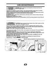
... time to dry before reinstalling into the unit. 5) Replace the air filter and cover. 6) Replacement air filter information is restricted, which reduces cooling efficiency. If the air filter becomes clogged with a dry soft cloth. 5) Clean the air intake grill and replace. A mild detergent (diswashing liquid) is located at the upper rear side of the unit. 1) To remove the air filter: Pull the air filter cover upward in the direction of the arrow (Fig. 5) and remove the air filter. 2) Dust...
... time to dry before reinstalling into the unit. 5) Replace the air filter and cover. 6) Replacement air filter information is restricted, which reduces cooling efficiency. If the air filter becomes clogged with a dry soft cloth. 5) Clean the air intake grill and replace. A mild detergent (diswashing liquid) is located at the upper rear side of the unit. 1) To remove the air filter: Pull the air filter cover upward in the direction of the arrow (Fig. 5) and remove the air filter. 2) Dust...
Product Manual
Page 13
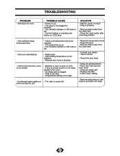
...; Reset the timer • Remove drain water from room • Clean air intake grill • Replace the filter • Lower temp. tank is full • Current leaking or pressing test button on rear bottom and drain out water 12 TROUBLESHOOTING PROBLEM • Unit does not work POSSIBLE CAUSE • Power is out • The plug is not plugged in properly • Remove drain water from the drain tank • Press the reset button after resolving problem • Unit suddenly stops during operation • Unit...
...; Reset the timer • Remove drain water from room • Clean air intake grill • Replace the filter • Lower temp. tank is full • Current leaking or pressing test button on rear bottom and drain out water 12 TROUBLESHOOTING PROBLEM • Unit does not work POSSIBLE CAUSE • Power is out • The plug is not plugged in properly • Remove drain water from the drain tank • Press the reset button after resolving problem • Unit suddenly stops during operation • Unit...


