
Product Manual
Page 2
... be required to take adequate measures. Este es un producto de Clase A. Warnung! Dies ist ein Produkt der Klasse A. Il presente prodotto appartiene alla classe A. D-Link Unified Access System User Manual FCC Warning This equipment has been tested and found to comply with this manual, may be required to correct the...
... be required to take adequate measures. Este es un producto de Clase A. Warnung! Dies ist ein Produkt der Klasse A. Il presente prodotto appartiene alla classe A. D-Link Unified Access System User Manual FCC Warning This equipment has been tested and found to comply with this manual, may be required to correct the...
Product Manual
Page 3
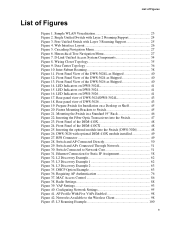
... Using the Web Interface 26 Using the Command-Line Interface 28 Using SNMP 29 Wireless System Features and Standards Support 30 2 Planning the D-Link Unified Access System Network 33 System Requirements 33 WLAN Topology Considerations 34 Access Point-to-Switch Discovery 36 Access Point Placement 36 Network Planning to Support Layer 3 Roaming 37...
... Using the Web Interface 26 Using the Command-Line Interface 28 Using SNMP 29 Wireless System Features and Standards Support 30 2 Planning the D-Link Unified Access System Network 33 System Requirements 33 WLAN Topology Considerations 34 Access Point-to-Switch Discovery 36 Access Point Placement 36 Network Planning to Support Layer 3 Roaming 37...
Product Manual
Page 4
...Redundant Power System 49 Connecting the Switch 49 Connecting the Switch to the Network 50 Connecting the Switch and AP Directly 50 Connecting the Switch and AP through the L2/L3 Network 51 Connecting to the Core Network 51 4 Installing the D-Link Unified Access System 53 System ... Local Database 83 Access Point Profiles 83 Networks 84 Local Access Point Database 84 Configuring AAA and RADIUS Settings 85 Configuring Wireless Radio Settings 87 Configuring SSID Settings 93 Managing Virtual Access Point Configuration 93 Configuring the Default Network 94 Enabling and Configuring...
...Redundant Power System 49 Connecting the Switch 49 Connecting the Switch to the Network 50 Connecting the Switch and AP Directly 50 Connecting the Switch and AP through the L2/L3 Network 51 Connecting to the Core Network 51 4 Installing the D-Link Unified Access System 53 System ... Local Database 83 Access Point Profiles 83 Networks 84 Local Access Point Database 84 Configuring AAA and RADIUS Settings 85 Configuring Wireless Radio Settings 87 Configuring SSID Settings 93 Managing Virtual Access Point Configuration 93 Configuring the Default Network 94 Enabling and Configuring...
Product Manual
Page 6
...Wireless Network 189 Importing and Configuring a Background Image 190 Setting Up the Graph Components 191 Creating a New Graph 191 Graphing the WLAN Components 194 Understanding the Menu Bar Options 196 Legend Menu 198 Managing the Graph 201 A D-Link Unified Access System Default Settings 203 Default D-Link Unified Switch... Settings 203 Default D-Link Access Point Settings 204 Default D-Link Access Point Profile Settings 205 Default Captive Portal Settings ...
...Wireless Network 189 Importing and Configuring a Background Image 190 Setting Up the Graph Components 191 Creating a New Graph 191 Graphing the WLAN Components 194 Understanding the Menu Bar Options 196 Legend Menu 198 Managing the Graph 201 A D-Link Unified Access System Default Settings 203 Default D-Link Unified Switch... Settings 203 Default D-Link Access Point Settings 204 Default D-Link Access Point Profile Settings 205 Default Captive Portal Settings ...

Product Manual
Page 8
D-Link Unified Access System User Manual 8 © 2001- 2008 D-Link Corporation. All Rights Reserved.
D-Link Unified Access System User Manual 8 © 2001- 2008 D-Link Corporation. All Rights Reserved.
Product Manual
Page 9
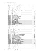
... 7. D-Link Unified Access System Components 34 Figure 8. Prepare Switch for Static IP Assignment 58 Figure 32. Inserting the Fiber-Optic Transceivers into the Switch (DWS-3026 48 Figure 26. Front Panel of DWS-3026 43 Figure 19. Switch and AP Connected Directly 50 Figure 29. Peer Unified Switch with Layer 2 Roaming Support 24 Figure 3. Fasten Mounting Brackets to the Wireless...
... 7. D-Link Unified Access System Components 34 Figure 8. Prepare Switch for Static IP Assignment 58 Figure 32. Inserting the Fiber-Optic Transceivers into the Switch (DWS-3026 48 Figure 26. Front Panel of DWS-3026 43 Figure 19. Switch and AP Connected Directly 50 Figure 29. Peer Unified Switch with Layer 2 Roaming Support 24 Figure 3. Fasten Mounting Brackets to the Wireless...
Product Manual
Page 10
...182 Figure 87. Client Detail 184 Figure 89. Static WEP Configuration 102 Figure 46. Peer Switch Status 127 Figure 60. Managed AP Status 130 Figure 62. Client Authentication Failure Status 152...Figure 85. Manual Channel Plan 114 Figure 53. Global WLAN Status 124 Figure 58. Wireless Discovery Status 126 Figure 59. Authentication Failed AP Status 142 Figure 64. RF Scan .... SNMP Trap Configuration 161 Figure 74. Client Statistics 185 10 © 2001- 2008 D-Link Corporation. WPA Personal Configuration 104 Figure 47. RF Channel Plan and Power Configuration 111 Figure ...
...182 Figure 87. Client Detail 184 Figure 89. Static WEP Configuration 102 Figure 46. Peer Switch Status 127 Figure 60. Managed AP Status 130 Figure 62. Client Authentication Failure Status 152...Figure 85. Manual Channel Plan 114 Figure 53. Global WLAN Status 124 Figure 58. Wireless Discovery Status 126 Figure 59. Authentication Failed AP Status 142 Figure 64. RF Scan .... SNMP Trap Configuration 161 Figure 74. Client Statistics 185 10 © 2001- 2008 D-Link Corporation. WPA Personal Configuration 104 Figure 47. RF Channel Plan and Power Configuration 111 Figure ...

Product Manual
Page 12
D-Link Unified Access System User Manual 12 © 2001- 2008 D-Link Corporation. All Rights Reserved.
D-Link Unified Access System User Manual 12 © 2001- 2008 D-Link Corporation. All Rights Reserved.

Product Manual
Page 14
...CP Configuration 170 Table 59. Global Captive Portal Status 179 Table 65. CP - SNMP Trap Configuration 187 Table 74. Switch Defaults 203 Table 77. RADIUS Attributes for Wireless Client MAC Authentication . . . . . 211 Table 83. L3 Tunnel Status Values 223 Table 84. All Rights Reserved... Portal User RADIUS Attributes 176 Table 63. Component Information 201 Table 76. VLAN Priority Tags 234 14 © 2001- 2008 D-Link Corporation. Local User Summary 175 Table 61. Interface Activation Status 181 Table 67. Interface - Failed Client Status 152 Table 51. ...
...CP Configuration 170 Table 59. Global Captive Portal Status 179 Table 65. CP - SNMP Trap Configuration 187 Table 74. Switch Defaults 203 Table 77. RADIUS Attributes for Wireless Client MAC Authentication . . . . . 211 Table 83. L3 Tunnel Status Values 223 Table 84. All Rights Reserved... Portal User RADIUS Attributes 176 Table 63. Component Information 201 Table 76. VLAN Priority Tags 234 14 © 2001- 2008 D-Link Corporation. Local User Summary 175 Table 61. Interface Activation Status 181 Table 67. Interface - Failed Client Status 152 Table 51. ...
Product Manual
Page 15
..." on page 155 • Chapter 9, "Configuring the Captive Portal" on page 167 • Chapter 10, "Visualizing the Wireless Network" on page 189 • Appendix A, "D-Link Unified Access System Default Settings" on page 203 • Appendix B, "Configuring the External RADIUS Server" on page 207 •... so on page 243 Document Conventions This section describes the conventions this guide is intended for the person responsible for the D-Link Unified Access System. CAUTION: A Caution provides information about a feature or technology. About This Document About This Document This guide...
..." on page 155 • Chapter 9, "Configuring the Captive Portal" on page 167 • Chapter 10, "Visualizing the Wireless Network" on page 189 • Appendix A, "D-Link Unified Access System Default Settings" on page 203 • Appendix B, "Configuring the External RADIUS Server" on page 207 •... so on page 243 Document Conventions This section describes the conventions this guide is intended for the person responsible for the D-Link Unified Access System. CAUTION: A Caution provides information about a feature or technology. About This Document About This Document This guide...

Product Manual
Page 16
...the mutually exclusive choices. Indicates an optional fixed parameter. Do not service any of choices. All Rights Reserved. D-Link Unified Access System User Manual This guide uses the typographical conventions that are marked with the triangular symbol with a ...a parameter is damaged. - Indicates that you follow service markings. Example Click Submit to water. - See "About This Document" on page 15. (switch-prompt)# show network value [value] [] {choice1 | choice2} choice1 | choice2 [{choice1 | choice2}] Safety Instructions Use the following precautions. •...
...the mutually exclusive choices. Indicates an optional fixed parameter. Do not service any of choices. All Rights Reserved. D-Link Unified Access System User Manual This guide uses the typographical conventions that are marked with the triangular symbol with a ...a parameter is damaged. - Indicates that you follow service markings. Example Click Submit to water. - See "About This Document" on page 15. (switch-prompt)# show network value [value] [] {choice1 | choice2} choice1 | choice2 [{choice1 | choice2}] Safety Instructions Use the following precautions. •...
Product Manual
Page 18
...absence of the branch circuit rating. • Ensure that suitable grounding is omitted or disconnected. 18 © 2001- 2008 D-Link Corporation. Also refer to the rack installation documentation accompanying the system and the rack for rack stability and safety. Contact the ... After a component is level and stable before installing components in the rack. • After installing system/components in a rack. D-Link Unified Access System User Manual General Precautions for Rack-Mountable Products Observe the following precautions for specific caution statements and procedures. • ...
...absence of the branch circuit rating. • Ensure that suitable grounding is omitted or disconnected. 18 © 2001- 2008 D-Link Corporation. Also refer to the rack installation documentation accompanying the system and the rack for rack stability and safety. Contact the ... After a component is level and stable before installing components in the rack. • After installing system/components in a rack. D-Link Unified Access System User Manual General Precautions for Rack-Mountable Products Observe the following precautions for specific caution statements and procedures. • ...

Product Manual
Page 20
All Rights Reserved. D-Link Unified Access System User Manual 20 © 2001- 2008 D-Link Corporation.
All Rights Reserved. D-Link Unified Access System User Manual 20 © 2001- 2008 D-Link Corporation.

Product Manual
Page 21
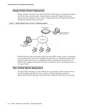
... WLAN deployment while providing state-of 8000 wireless clients. The peer Unified Switches can manage up to 48 D-Link Access Points. The DWS-3024L Unified Switch can manage up to 24 D-Link Access Points, whereas the DWS-3024 and the DWS-3026 switches can be directly connected to four peer D-Link Unified Switches that provides secure wireless connectivity and seamless layer 2 and layer...
... WLAN deployment while providing state-of 8000 wireless clients. The peer Unified Switches can manage up to 48 D-Link Access Points. The DWS-3024L Unified Switch can manage up to 24 D-Link Access Points, whereas the DWS-3024 and the DWS-3026 switches can be directly connected to four peer D-Link Unified Switches that provides secure wireless connectivity and seamless layer 2 and layer...

Product Manual
Page 22
...DWL-8500AP radios operate in Managed Mode. The D-Link Unified Access System works with D-Link Access Points in Managed Mode, the Administrator Web UI services on the wired and wireless LAN. The DWL3500AP radio and one of the D-Link Unified Access System, and you manage it by connecting...is appropriate for any size network. If you start out with the following D-Link switches: • DWS-3024 (24 GE ports) • DWS-3024L (24 GE ports) • DWS-3026 (24 GE ports + 2 10G ports) D-Link Access Point The D-Link Access Point can operate in one radio, and the DWL-8500AP supports two...
...DWL-8500AP radios operate in Managed Mode. The D-Link Unified Access System works with D-Link Access Points in Managed Mode, the Administrator Web UI services on the wired and wireless LAN. The DWL3500AP radio and one of the D-Link Unified Access System, and you manage it by connecting...is appropriate for any size network. If you start out with the following D-Link switches: • DWS-3024 (24 GE ports) • DWS-3024L (24 GE ports) • DWS-3026 (24 GE ports + 2 10G ports) D-Link Access Point The D-Link Access Point can operate in one radio, and the DWL-8500AP supports two...

Product Manual
Page 23
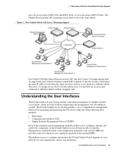
... building layout to help you use depends on your WLAN. WLAN Visualization detects and displays the D-Link Unified Switch, D-Link Access Points, other access points, and all wireless clients associated with a D-Link Unified Switch that need greater roaming capabilities for wireless clients, a deployment with color-coded channels to customize the network view. The graph also shows a peer...
... building layout to help you use depends on your WLAN. WLAN Visualization detects and displays the D-Link Unified Switch, D-Link Access Points, other access points, and all wireless clients associated with a D-Link Unified Switch that need greater roaming capabilities for wireless clients, a deployment with color-coded channels to customize the network view. The graph also shows a peer...
Product Manual
Page 24
...and range of a different AP. Figure 3 shows a D-Link Unified Access System deployment that manages three D-Link Access Points. Each peer Unified Switch can manage 24 © 2001- 2008 D-Link Corporation. The client keeps the same IP address and does not...Switch Terminal with one D-Link Unified Switch that utilizes three peer Unified Switches. All Rights Reserved. Figure 2 shows a deployment with Direct Serial Connection Remote Management Station L2 Network AP 1 AP 2 AP 3 When the APs are managed by the switch simultaneously or on the same subnet and have the same SSID, wireless...
...and range of a different AP. Figure 3 shows a D-Link Unified Access System deployment that manages three D-Link Access Points. Each peer Unified Switch can manage 24 © 2001- 2008 D-Link Corporation. The client keeps the same IP address and does not...Switch Terminal with one D-Link Unified Switch that utilizes three peer Unified Switches. All Rights Reserved. Figure 2 shows a deployment with Direct Serial Connection Remote Management Station L2 Network AP 1 AP 2 AP 3 When the APs are managed by the switch simultaneously or on the same subnet and have the same SSID, wireless...
Product Manual
Page 25
...User Interfaces The D-Link Unified Access System enables centralized management of the D-Link Unified Access System up to 48 access points (DWS-3024 and DWS-3026) or 24 access points (DWS-3024L). To support this, peer Unified Switches establish IPv4 tunnels ...so that provides control for managing and monitoring the WLAN by Unified Switch 2 Peer Unified Switches share information about APs and allow Layer 3 roaming among them. The Layer 3 roaming service allows wireless...
...User Interfaces The D-Link Unified Access System enables centralized management of the D-Link Unified Access System up to 48 access points (DWS-3024 and DWS-3026) or 24 access points (DWS-3024L). To support this, peer Unified Switches establish IPv4 tunnels ...so that provides control for managing and monitoring the WLAN by Unified Switch 2 Peer Unified Switches share information about APs and allow Layer 3 roaming among them. The Layer 3 roaming service allows wireless...
Product Manual
Page 26
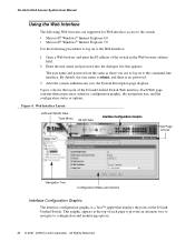
... the system authenticates you use to the Web Interface: 1. Open a Web browser and enter the IP address of the D-Link Unified Switch Web interface. Web Interface Layout LAN and WLAN Tabs Tools Menu WLAN Tabs Interface Configuration Graphic Help Page Access Navigation Tree Configuration... following procedures to log on to log on the D-Link Unified Switch. Each Web page contains three main areas: interface configuration graphic, the navigation tree, and the configuration status or options. All Rights Reserved. D-Link Unified Access System User Manual Using the Web Interface The...
... the system authenticates you use to the Web Interface: 1. Open a Web browser and enter the IP address of the D-Link Unified Switch Web interface. Web Interface Layout LAN and WLAN Tabs Tools Menu WLAN Tabs Interface Configuration Graphic Help Page Access Navigation Tree Configuration... following procedures to log on to log on the D-Link Unified Switch. Each Web page contains three main areas: interface configuration graphic, the navigation tree, and the configuration status or options. All Rights Reserved. D-Link Unified Access System User Manual Using the Web Interface The...

Product Manual
Page 27
... changes permanent. Click Logout to the right of the page. This menu contains the same option as the navigation menu on the left of the D-Link Unified Access System Click the port you can input information into fields or select options from drop-down menus. A folder or subfolder has no corresponding...
... changes permanent. Click Logout to the right of the page. This menu contains the same option as the navigation menu on the left of the D-Link Unified Access System Click the port you can input information into fields or select options from drop-down menus. A folder or subfolder has no corresponding...


