Product Manual
Page 9
...Layout 26 Figure 5. D-Link Unified Access System Components 34 Figure 8. Front Panel View of the DWS-3026 as Shipped 40 Figure 12. LED Indicators on DWS-3024L 41 Figure 15. Switch and APs Connected Through Network 51 Figure 30. Networks Available to the Wireless Client 98 Figure 43... Support 24 Figure 3. L2 Discovery Example 62 Figure 33. Radio Settings 88 Figure 39. Peer Unified Switch with Layer 3 Roaming Support 25 Figure 4. Hierarchical Tree Navigation Menu 27 Figure 7. L3 Discovery Example 2 63 Figure 35. Front Panel of the DWS-3024 as Shipped 40 Figure 13...
...Layout 26 Figure 5. D-Link Unified Access System Components 34 Figure 8. Front Panel View of the DWS-3026 as Shipped 40 Figure 12. LED Indicators on DWS-3024L 41 Figure 15. Switch and APs Connected Through Network 51 Figure 30. Networks Available to the Wireless Client 98 Figure 43... Support 24 Figure 3. L2 Discovery Example 62 Figure 33. Radio Settings 88 Figure 39. Peer Unified Switch with Layer 3 Roaming Support 25 Figure 4. Hierarchical Tree Navigation Menu 27 Figure 7. L3 Discovery Example 2 63 Figure 35. Front Panel of the DWS-3024 as Shipped 40 Figure 13...

Product Manual
Page 21
.... You can manage up to 48 D-Link Access Points. D-Link Unified Access System Components 21 The DWS-3024L Unified Switch can manage up to 24 D-Link Access Points, whereas the DWS-3024 and the DWS-3026 switches can configure up to four peer D-Link Unified Switches that enables WLAN deployment while providing state-of-the-art wireless networking features. This chapter contains the...
.... You can manage up to 48 D-Link Access Points. D-Link Unified Access System Components 21 The DWS-3024L Unified Switch can manage up to 24 D-Link Access Points, whereas the DWS-3024 and the DWS-3026 switches can configure up to four peer D-Link Unified Switches that enables WLAN deployment while providing state-of-the-art wireless networking features. This chapter contains the...

Product Manual
Page 22
... the wired and wireless LAN. The DWS-3024L manages up to 24 access points (APs), and the DWS-3024 and DWS-3026 switches manage up to 48 APs. The Standalone Mode is useful for both network and element control. The DWL3500AP radio and one of two modes: Standalone Mode or Managed Mode. The D-Link Unified Access System works...
... the wired and wireless LAN. The DWS-3024L manages up to 24 access points (APs), and the DWS-3024 and DWS-3026 switches manage up to 48 APs. The Standalone Mode is useful for both network and element control. The DWL3500AP radio and one of two modes: Standalone Mode or Managed Mode. The D-Link Unified Access System works...
Product Manual
Page 25
... methods enables you use to 48 access points (DWS-3024 and DWS-3026) or 24 access points (DWS-3024L). The Unified Switch and the APs it manages do not need to different subnets without dropping calls. Understanding the User Interfaces The D-Link Unified Access System enables centralized management of multiple wireless access points, which not only facilitates deployment...
... methods enables you use to 48 access points (DWS-3024 and DWS-3026) or 24 access points (DWS-3024L). The Unified Switch and the APs it manages do not need to different subnets without dropping calls. Understanding the User Interfaces The D-Link Unified Access System enables centralized management of multiple wireless access points, which not only facilitates deployment...

Product Manual
Page 31
... Dual Radio Support - 1 Overview of the D-Link Access Point features and standards support: • WLAN and IEEE Standards - Peer-to 24 APs (DWS-3024L) or 48 APs (DWS-3024 and DWS-3026) per radio. Station blacklisting - Auto AP... image download - You can configure a unique SSID and security policy on each VAP. IEEE 802.11d - IEEE 802.11e (WMM) - IEEE 802.11i (WPA2) - IEEE802.3af PoE Support • WLAN RF Features - Load Balancing - TELEC 4.9GHZ 802.11a modes - Wireless...
... Dual Radio Support - 1 Overview of the D-Link Access Point features and standards support: • WLAN and IEEE Standards - Peer-to 24 APs (DWS-3024L) or 48 APs (DWS-3024 and DWS-3026) per radio. Station blacklisting - Auto AP... image download - You can configure a unique SSID and security policy on each VAP. IEEE 802.11d - IEEE 802.11e (WMM) - IEEE 802.11i (WPA2) - IEEE802.3af PoE Support • WLAN RF Features - Load Balancing - TELEC 4.9GHZ 802.11a modes - Wireless...
Product Manual
Page 39
... through the L2/L3 Network - Connecting the Switch to the Network - The DWS-3024/DWS-3024L and DWS-3026 have slightly different front and back panels based on the switch. Installing the SFP ports - Connecting the Switch and AP Directly - Front Panel Components - Hardware Overview 39 3 Installing the Hardware This chapter provides instructions for installing the D-Link DWS-3024, DWS-3024L, and DWS-3026 switch hardware...
... through the L2/L3 Network - Connecting the Switch to the Network - The DWS-3024/DWS-3024L and DWS-3026 have slightly different front and back panels based on the switch. Installing the SFP ports - Connecting the Switch and AP Directly - Front Panel Components - Hardware Overview 39 3 Installing the Hardware This chapter provides instructions for installing the D-Link DWS-3024, DWS-3024L, and DWS-3026 switch hardware...

Product Manual
Page 40
Front Panel View of the DWS-3026 as Shipped Figure 12. All Rights Reserved. Front Panel View of the DWS-3024L as Shipped 40 © 2001- 2008 D-Link Corporation. Front Panel View of LED indicators for Power, Console, RPS, PoE, and Link/Act/Speed for each port on the Switch including 10GE Ports for optional modules and SFP port LEDs. Table 2 describes the LED indicators in more detail. D-Link Unified Access System User Manual Front Panel Components The front panel of the Switch consists of the DWS-3024 as Shipped Figure 13. Figure 11.
Front Panel View of the DWS-3026 as Shipped Figure 12. All Rights Reserved. Front Panel View of the DWS-3024L as Shipped 40 © 2001- 2008 D-Link Corporation. Front Panel View of LED indicators for Power, Console, RPS, PoE, and Link/Act/Speed for each port on the Switch including 10GE Ports for optional modules and SFP port LEDs. Table 2 describes the LED indicators in more detail. D-Link Unified Access System User Manual Front Panel Components The front panel of the Switch consists of the DWS-3024 as Shipped Figure 13. Figure 11.
Product Manual
Page 41
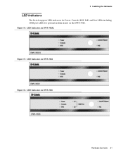
Figure 14. LED Indicators on DWS-3026 Hardware Overview 41 LED Indicators on DWS-3024 Figure 16. LED Indicators on the DWS-3026. 3 Installing the Hardware LED Indicators The Switch supports LED indicators for Power, Console, RPS, PoE, and Port LEDs including 10GE port LEDs for optional module inserts on DWS-3024L Figure 15.
Figure 14. LED Indicators on DWS-3026 Hardware Overview 41 LED Indicators on DWS-3024 Figure 16. LED Indicators on the DWS-3026. 3 Installing the Hardware LED Indicators The Switch supports LED indicators for Power, Console, RPS, PoE, and Port LEDs including 10GE port LEDs for optional module inserts on DWS-3024L Figure 15.

Product Manual
Page 43
... activity on each side of the Switch dissipate heat. Rear Panel Description The AC power connector is no link/activity on the port. Plug the female connector of the provided power cord into this socket, and plug the male side of the DWS-3024/DWS-3024L contains an AC power connector, a... system fan vent, and a redundant power supply connector. The Switch automatically adjusts its power...
... activity on each side of the Switch dissipate heat. Rear Panel Description The AC power connector is no link/activity on the port. Plug the female connector of the provided power cord into this socket, and plug the male side of the DWS-3024/DWS-3024L contains an AC power connector, a... system fan vent, and a redundant power supply connector. The Switch automatically adjusts its power...


