Product Manual
Page 3
... Using the Web Interface 26 Using the Command-Line Interface 28 Using SNMP 29 Wireless System Features and Standards Support 30 2 Planning the D-Link Unified Access System Network 33 System Requirements 33 WLAN Topology Considerations 34 Access Point-to-Switch Discovery 36 Access Point Placement 36 Network Planning to Support Layer 3 Roaming 37...
... Using the Web Interface 26 Using the Command-Line Interface 28 Using SNMP 29 Wireless System Features and Standards Support 30 2 Planning the D-Link Unified Access System Network 33 System Requirements 33 WLAN Topology Considerations 34 Access Point-to-Switch Discovery 36 Access Point Placement 36 Network Planning to Support Layer 3 Roaming 37...
Product Manual
Page 4
...Redundant Power System 49 Connecting the Switch 49 Connecting the Switch to the Network 50 Connecting the Switch and AP Directly 50 Connecting the Switch and AP through the L2/L3 Network 51 Connecting to the Core Network 51 4 Installing the D-Link Unified Access System 53 System ... Local Database 83 Access Point Profiles 83 Networks 84 Local Access Point Database 84 Configuring AAA and RADIUS Settings 85 Configuring Wireless Radio Settings 87 Configuring SSID Settings 93 Managing Virtual Access Point Configuration 93 Configuring the Default Network 94 Enabling and Configuring...
...Redundant Power System 49 Connecting the Switch 49 Connecting the Switch to the Network 50 Connecting the Switch and AP Directly 50 Connecting the Switch and AP through the L2/L3 Network 51 Connecting to the Core Network 51 4 Installing the D-Link Unified Access System 53 System ... Local Database 83 Access Point Profiles 83 Networks 84 Local Access Point Database 84 Configuring AAA and RADIUS Settings 85 Configuring Wireless Radio Settings 87 Configuring SSID Settings 93 Managing Virtual Access Point Configuration 93 Configuring the Default Network 94 Enabling and Configuring...
Product Manual
Page 5
... Access Point Management 119 Enabling AP Debugging 120 Adjusting the Channel and Power 120 7 Monitoring Status and Statistics 123 Monitoring Wireless Global Information 123 Viewing IP Discovery Status 126 Monitoring Peer Switch Status 126 Monitoring All Access Points 127 Monitoring Managed Access Point Status 130 Monitoring Managed AP Statistics 138 Viewing Access...
... Access Point Management 119 Enabling AP Debugging 120 Adjusting the Channel and Power 120 7 Monitoring Status and Statistics 123 Monitoring Wireless Global Information 123 Viewing IP Discovery Status 126 Monitoring Peer Switch Status 126 Monitoring All Access Points 127 Monitoring Managed Access Point Status 130 Monitoring Managed AP Statistics 138 Viewing Access...
Product Manual
Page 6
...Wireless Network 189 Importing and Configuring a Background Image 190 Setting Up the Graph Components 191 Creating a New Graph 191 Graphing the WLAN Components 194 Understanding the Menu Bar Options 196 Legend Menu 198 Managing the Graph 201 A D-Link Unified Access System Default Settings 203 Default D-Link Unified Switch... Settings 203 Default D-Link Access Point Settings 204 Default D-Link Access Point Profile Settings 205 Default Captive Portal Settings ...
...Wireless Network 189 Importing and Configuring a Background Image 190 Setting Up the Graph Components 191 Creating a New Graph 191 Graphing the WLAN Components 194 Understanding the Menu Bar Options 196 Legend Menu 198 Managing the Graph 201 A D-Link Unified Access System Default Settings 203 Default D-Link Unified Switch... Settings 203 Default D-Link Access Point Settings 204 Default D-Link Access Point Profile Settings 205 Default Captive Portal Settings ...
Product Manual
Page 9
...48 Figure 24. L2 Discovery Example 62 Figure 33. DHCP Option Example 63 Figure 36. AP Profile With Five VAPs Enabled 98 Figure 42. Peer Unified Switch with Layer 2 ...Unified Switch with Layer 3 Roaming Support 25 Figure 4. Cascading Navigation Menu 27 Figure 6. D-Link Unified Access System Components 34 Figure 8. LED Indicators on DWS-3024 41 Figure 16. Prepare Switch for ... Fiber-Optic Transceivers into the Switch (DWS-3026 48 Figure 26. Inserting the optional module into the Switch 47 Figure 23. Switch Connected to the Wireless Client 98 Figure 43. L3...
...48 Figure 24. L2 Discovery Example 62 Figure 33. DHCP Option Example 63 Figure 36. AP Profile With Five VAPs Enabled 98 Figure 42. Peer Unified Switch with Layer 2 ...Unified Switch with Layer 3 Roaming Support 25 Figure 4. Cascading Navigation Menu 27 Figure 6. D-Link Unified Access System Components 34 Figure 8. LED Indicators on DWS-3024 41 Figure 16. Prepare Switch for ... Fiber-Optic Transceivers into the Switch (DWS-3026 48 Figure 26. Inserting the optional module into the Switch 47 Figure 23. Switch Connected to the Wireless Client 98 Figure 43. L3...
Product Manual
Page 10
... User Configuration 175 Figure 82. AP Upgrade Status 117 Figure 56. Wireless Discovery Status 126 Figure 59. Applying the AP Profile 158 Figure 72. Global Captive Portal Configuration 168 Figure 77. Peer Switch Status 127 Figure 60. Client Detail 184 Figure 89. AP Network Security...75. Global Captive Portal Configuration 177 Figure 83. Interface Capability Status 182 Figure 87. Client Statistics 185 10 © 2001- 2008 D-Link Corporation. Static WEP Configuration 102 Figure 46. Manual Channel Plan 114 Figure 53. RF Scan 144 Figure 65. Captive Portal Configuration 170 ...
... User Configuration 175 Figure 82. AP Upgrade Status 117 Figure 56. Wireless Discovery Status 126 Figure 59. Applying the AP Profile 158 Figure 72. Global Captive Portal Configuration 168 Figure 77. Peer Switch Status 127 Figure 60. Client Detail 184 Figure 89. AP Network Security...75. Global Captive Portal Configuration 177 Figure 83. Interface Capability Status 182 Figure 87. Client Statistics 185 10 © 2001- 2008 D-Link Corporation. Static WEP Configuration 102 Figure 46. Manual Channel Plan 114 Figure 53. RF Scan 144 Figure 65. Captive Portal Configuration 170 ...

Product Manual
Page 13
LED Description 42 Table 3. Wireless Network Configuration 95 Table 13. Static WEP 102 Table 14. Valid Access Point Summary 106 Table 16. Peer Switch Status 127 Table 26. Detailed Managed Access Point Status 132 Table 29. Managed Access Point WLAN Summary ...Statistics 139 Table 35. Access Point Authentication Failure Status 143 Table 40. Basic Wireless Global Configuration 56 Table 4. Static WPA ...
LED Description 42 Table 3. Wireless Network Configuration 95 Table 13. Static WEP 102 Table 14. Valid Access Point Summary 106 Table 16. Peer Switch Status 127 Table 26. Detailed Managed Access Point Status 132 Table 29. Managed Access Point WLAN Summary ...Statistics 139 Table 35. Access Point Authentication Failure Status 143 Table 40. Basic Wireless Global Configuration 56 Table 4. Static WPA ...

Product Manual
Page 14
... CP Activation and Activity Status 180 Table 66. SNMP Trap Configuration 187 Table 74. Default AP Settings 204 Table 78. RADIUS Attributes for Wireless Client MAC Authentication . . . . . 211 Table 83. Associated Client SSID Status 149 Table 45. Associated Client Summary Statistics 150 Table ...Captive Portal Settings 206 Table 80. Client Status 186 Table 72. D-Link Unified Access System User Manual Table 44. Failed Client Status 152 Table 51. WLAN Visualization Menu Bar Options 196 Table 75. Switch Defaults 203 Table 77. Associated Client VAP Status 149 Table 46. SNMP...
... CP Activation and Activity Status 180 Table 66. SNMP Trap Configuration 187 Table 74. Default AP Settings 204 Table 78. RADIUS Attributes for Wireless Client MAC Authentication . . . . . 211 Table 83. Associated Client SSID Status 149 Table 45. Associated Client Summary Statistics 150 Table ...Captive Portal Settings 206 Table 80. Client Status 186 Table 72. D-Link Unified Access System User Manual Table 44. Failed Client Status 152 Table 51. WLAN Visualization Menu Bar Options 196 Table 75. Switch Defaults 203 Table 77. Associated Client VAP Status 149 Table 46. SNMP...

Product Manual
Page 16
...enter a value in place of choices. Indicates that you follow service markings. See "About This Document" on page 15. (switch-prompt)# show network value [value] [] {choice1 | choice2} choice1 | choice2 [{choice1 | choice2}] Safety Instructions Use the following... precautions. • Observe and follow the operating instructions. 16 © 2001- 2008 D-Link Corporation. Only a trained service technician should service components inside them. Screen text, file names. Separates the mutually exclusive choices. Indicate ...
...enter a value in place of choices. Indicates that you follow service markings. See "About This Document" on page 15. (switch-prompt)# show network value [value] [] {choice1 | choice2} choice1 | choice2 [{choice1 | choice2}] Safety Instructions Use the following... precautions. • Observe and follow the operating instructions. 16 © 2001- 2008 D-Link Corporation. Only a trained service technician should service components inside them. Screen text, file names. Separates the mutually exclusive choices. Indicate ...

Product Manual
Page 17
... so that they cannot be greater than the ratings marked on the product. • To help avoid damaging your system, be sure the voltage selection Switch (if provided) on the electrical ratings label. If you must be sure that is set to match the power available at your local/national wiring...
... so that they cannot be greater than the ratings marked on the product. • To help avoid damaging your system, be sure the voltage selection Switch (if provided) on the electrical ratings label. If you must be sure that is set to match the power available at your local/national wiring...

Product Manual
Page 21
... state-of-the-art wireless networking features. The peer Unified Switches can configure up to each other, separated by peer Unified Switches without losing network connections. The DWS-3024L Unified Switch can manage up to 24 D-Link Access Points, whereas the DWS-3024 and the DWS-3026 switches can handle up to 48 D-Link Access Points. The switch tracks the status and...
... state-of-the-art wireless networking features. The peer Unified Switches can configure up to each other, separated by peer Unified Switches without losing network connections. The DWS-3024L Unified Switch can manage up to 24 D-Link Access Points, whereas the DWS-3024 and the DWS-3026 switches can handle up to 48 D-Link Access Points. The switch tracks the status and...

Product Manual
Page 22
... In Managed Mode, the D-Link Access Point is appropriate for small networks with the following D-Link switches: • DWS-3024 (24 GE ports) • DWS-3024L (24 GE ports) • DWS-3026 (24 GE ports + 2 10G ports) D-Link Access Point The D-Link Access Point can easily transition ... eight virtual access points (VAPs) on the wired and wireless LAN. All Rights Reserved. Access is limited to 48 APs. D-Link Unified Access System User Manual D-Link Unified Switch The D-Link Unified Switch handles Layer 2, 3, and 4 switching and routing functions for traffic on each support a unique ...
... In Managed Mode, the D-Link Access Point is appropriate for small networks with the following D-Link switches: • DWS-3024 (24 GE ports) • DWS-3024L (24 GE ports) • DWS-3026 (24 GE ports + 2 10G ports) D-Link Access Point The D-Link Access Point can easily transition ... eight virtual access points (VAPs) on the wired and wireless LAN. All Rights Reserved. Access is limited to 48 APs. D-Link Unified Access System User Manual D-Link Unified Switch The D-Link Unified Switch handles Layer 2, 3, and 4 switching and routing functions for traffic on each support a unique ...

Product Manual
Page 23
... network view. Sample WLAN Visualization The WLAN Visualization tool provides an AP power display with a D-Link Unified Switch that manages a few D-Link Access Points. WLAN Visualization detects and displays the D-Link Unified Switch, D-Link Access Points, other access points, and all wireless clients associated with multiple peer switches that each manage several APs might require only one Unified...
... network view. Sample WLAN Visualization The WLAN Visualization tool provides an AP power display with a D-Link Unified Switch that manages a few D-Link Access Points. WLAN Visualization detects and displays the D-Link Unified Switch, D-Link Access Points, other access points, and all wireless clients associated with multiple peer switches that each manage several APs might require only one Unified...
Product Manual
Page 24
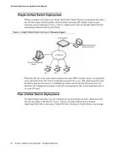
... Connection Remote Management Station L2 Network AP 1 AP 2 AP 3 When the APs are managed by the switch simultaneously or on the same subnet and have the same SSID, wireless clients can manage 24 © 2001- 2008 D-Link Corporation. Peer Unified Switch Deployment To support larger networks, you deploy a D-Link Access Point, the D-Link Unified Switch can automatically detect...
... Connection Remote Management Station L2 Network AP 1 AP 2 AP 3 When the APs are managed by the switch simultaneously or on the same subnet and have the same SSID, wireless clients can manage 24 © 2001- 2008 D-Link Corporation. Peer Unified Switch Deployment To support larger networks, you deploy a D-Link Access Point, the D-Link Unified Switch can automatically detect...
Product Manual
Page 25
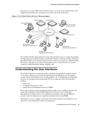
... requirements, and on the same subnet. The Layer 3 roaming service allows wireless phone users to roam between access points connected to 48 access points (DWS-3024 and DWS-3026) or 24 access points (DWS-3024L). Understanding the User Interfaces 25 Management is standards-based, with an... access point in the standard MIBs. 1 Overview of the D-Link Unified Access System up to different subnets without dropping calls. The Unified Switch and ...
... requirements, and on the same subnet. The Layer 3 roaming service allows wireless phone users to roam between access points connected to 48 access points (DWS-3024 and DWS-3026) or 24 access points (DWS-3024L). Understanding the User Interfaces 25 Management is standards-based, with an... access point in the standard MIBs. 1 Overview of the D-Link Unified Access System up to different subnets without dropping calls. The Unified Switch and ...
Product Manual
Page 26
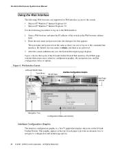
Open a Web browser and enter the IP address of the D-Link Unified Switch Web interface. After the system authenticates you use to log on to the command-line interface. D-Link Unified Access System User Manual Using the Web Interface The following procedures to log on to configuration and monitoring options.... All Rights Reserved. Enter the user name and password into the dialogue box that displays the ports on the D-Link Unified Switch. Figure 4 shows the layout of the switch in the Web browser address field. 2. Figure 4. This graphic appears at the top of each page to provide ...
Open a Web browser and enter the IP address of the D-Link Unified Switch Web interface. After the system authenticates you use to log on to the command-line interface. D-Link Unified Access System User Manual Using the Web Interface The following procedures to log on to configuration and monitoring options.... All Rights Reserved. Enter the user name and password into the dialogue box that displays the ports on the D-Link Unified Switch. Figure 4 shows the layout of the switch in the Web browser address field. 2. Figure 4. This graphic appears at the top of each page to provide ...
Product Manual
Page 28
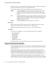
... specific commands. WLAN Tabs Many of the following command buttons are not available until you reboot the system. If there are saved even when you switch to access a specific page. Clicking the Refresh button refreshes the data on the panel. Tools Menu If you mouse over the Tool icon, a... and to the Web page where you can perform the related task. Using the Command-Line Interface The command-line interface (CLI) is a link to group functions for the page. Many pages also contain command buttons. You can execute the User EXEC mode commands in the Web interface: ...
... specific commands. WLAN Tabs Many of the following command buttons are not available until you reboot the system. If there are saved even when you switch to access a specific page. Clicking the Refresh button refreshes the data on the panel. Tools Menu If you mouse over the Tool icon, a... and to the Web page where you can perform the related task. Using the Command-Line Interface The command-line interface (CLI) is a link to group functions for the page. Many pages also contain command buttons. You can execute the User EXEC mode commands in the Web interface: ...
Product Manual
Page 29
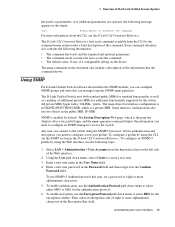
...8226; The command mode you can configure SNMP groups and users that the command shows. To configure an SNMPv3 profile by default. The D-Link Unified Switch uses both standard public MIBs for standard functionality as well as a number of additional private MIBs for the encryption scheme. SNMP is a... of eight or more alphanumeric characters in the public MIB, IF-MIB. The D-Link CLI Command Reference lists each command available from the hierarchical tree on the device. Using SNMP For D-Link Unified Switch software that includes the SNMP module, you must be in the User Name field....
...8226; The command mode you can configure SNMP groups and users that the command shows. To configure an SNMPv3 profile by default. The D-Link Unified Switch uses both standard public MIBs for standard functionality as well as a number of additional private MIBs for the encryption scheme. SNMP is a... of eight or more alphanumeric characters in the public MIB, IF-MIB. The D-Link CLI Command Reference lists each command available from the hierarchical tree on the device. Using SNMP For D-Link Unified Switch software that includes the SNMP module, you must be in the User Name field....
Product Manual
Page 30
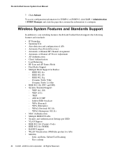
Click Submit. Wireless System Features and Standards Support In addition to configure. IEEE 802.11a - Dynamic Turbo 2.4 Ghz • IEEE 802.11h (TPC and DFS) • Security Standard ... for Radios: - To access configuration information for SNMPv1 or SNMPv2, click LAN > Administration > SNMP Manager and click the page that contains the information to core switching features, the D-Link Unified Switch supports the following features and standards: • IP Tunneling • Spanning Tree • Auto detection and configuration of APs • Automatic Peer...
Click Submit. Wireless System Features and Standards Support In addition to configure. IEEE 802.11a - Dynamic Turbo 2.4 Ghz • IEEE 802.11h (TPC and DFS) • Security Standard ... for Radios: - To access configuration information for SNMPv1 or SNMPv2, click LAN > Administration > SNMP Manager and click the page that contains the information to core switching features, the D-Link Unified Switch supports the following features and standards: • IP Tunneling • Spanning Tree • Auto detection and configuration of APs • Automatic Peer...

Product Manual
Page 31
... detection - Rogue Client detection - CLI - Up to -peer WLAN switch roaming • Intrusion Detection - IEEE 802.11g - IEEE 802.11i (WPA2) - Dual Radio Support - Web Management (SSL support) - D-Link WLAN Private MIB • Simultaneous AP upgrade • Centralized data forwarding...Assignment - CLI Management (SSH) - TFTP Wireless System Features and Standards Support 31 1 Overview of the D-Link Access Point features and standards support: • WLAN and IEEE Standards - Peer-to 24 APs (DWS-3024L) or 48 APs (DWS-3024 and DWS-3026) per radio. Station blacklisting - ...
... detection - Rogue Client detection - CLI - Up to -peer WLAN switch roaming • Intrusion Detection - IEEE 802.11g - IEEE 802.11i (WPA2) - Dual Radio Support - Web Management (SSL support) - D-Link WLAN Private MIB • Simultaneous AP upgrade • Centralized data forwarding...Assignment - CLI Management (SSH) - TFTP Wireless System Features and Standards Support 31 1 Overview of the D-Link Access Point features and standards support: • WLAN and IEEE Standards - Peer-to 24 APs (DWS-3024L) or 48 APs (DWS-3024 and DWS-3026) per radio. Station blacklisting - ...


