
Hardware Installation Guide
Page 3
... 3 Connecting the Switch...27 Switch to End Node ...27 Switch to Switch ...27 Connect to a Network Backbone or Server ...28 Chapter 4 Introduction to Switch Management ...29 Management Options ...29 Connecting the Console Port...29 Connecting to the Switch for the First Time ...31 Connecting to the Management Port...31 Password Protection...32 Assigning IP Addresses...32 SNMP Settings ...34 Traps ...34 Management Information Base (MIB) ...35 Chapter 5 Web-based Switch Configuration ...36 Introduction ...36 Logging onto the Web Manager ...36 Web-based User Interface...
... 3 Connecting the Switch...27 Switch to End Node ...27 Switch to Switch ...27 Connect to a Network Backbone or Server ...28 Chapter 4 Introduction to Switch Management ...29 Management Options ...29 Connecting the Console Port...29 Connecting to the Switch for the First Time ...31 Connecting to the Management Port...31 Password Protection...32 Assigning IP Addresses...32 SNMP Settings ...34 Traps ...34 Management Information Base (MIB) ...35 Chapter 5 Web-based Switch Configuration ...36 Introduction ...36 Logging onto the Web Manager ...36 Web-based User Interface...
Hardware Installation Guide
Page 5
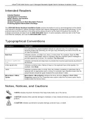
xStack® DGS-3620 Series Layer 3 Managed Stackable Gigabit Switch Hardware Installation Guide Intended Readers Intended Readers Typographical Conventions Notes, Notices, and Cautions Safety Instructions General Precautions for Rack-Mountable Products Protecting Against Electrostatic Discharge The DGS-3620 Series Hardware Installation Guide contains information for set up and management of the device. For example: Open the File menu and choose Cancel. Indicates commands and responses to prompts that helps make better use the DGS-3620-28PC Switch. Indicates a window name...
xStack® DGS-3620 Series Layer 3 Managed Stackable Gigabit Switch Hardware Installation Guide Intended Readers Intended Readers Typographical Conventions Notes, Notices, and Cautions Safety Instructions General Precautions for Rack-Mountable Products Protecting Against Electrostatic Discharge The DGS-3620 Series Hardware Installation Guide contains information for set up and management of the device. For example: Open the File menu and choose Cancel. Indicates commands and responses to prompts that helps make better use the DGS-3620-28PC Switch. Indicates a window name...
Hardware Installation Guide
Page 9
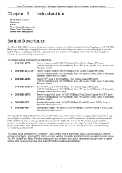
...), Four SFP+ ports (10GE), Layer 3 Stackable Managed Switch. • DGS-3620-28SC-DC: Twenty SFP ports (100/1000Mbps), Four Combo Copper/SFP ports (10/100/1000Mbps and 100/1000Mbps), Four SFP+ ports (10GE), Layer 3 Stackable Managed Switch with fiber-optical transceiver cabling in order to uplink various other switches to provide a gigabit Ethernet uplink in uplinking various network devices to the Switch, including PCs, hubs and other networking devices for a gigabit link that may be used with DC Power. • DGS-3620-28PC: Twenty Copper PoE ports...
...), Four SFP+ ports (10GE), Layer 3 Stackable Managed Switch. • DGS-3620-28SC-DC: Twenty SFP ports (100/1000Mbps), Four Combo Copper/SFP ports (10/100/1000Mbps and 100/1000Mbps), Four SFP+ ports (10GE), Layer 3 Stackable Managed Switch with fiber-optical transceiver cabling in order to uplink various other switches to provide a gigabit Ethernet uplink in uplinking various network devices to the Switch, including PCs, hubs and other networking devices for a gigabit link that may be used with DC Power. • DGS-3620-28PC: Twenty Copper PoE ports...
Hardware Installation Guide
Page 10
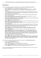
...Single IP Management, LLDP, LLDP-MED, Web-based GUI, CLI, Zmodem, TELNET Server/Client, TFTP Client, SNMP (versions 1, 2c, and 3), SNMP Traps, System Log, RMON, sFlow, BootP/DHCP Client, DHCP Auto-configuration, DHCP Server, DHCP Relay, DHCPv6 PD, UDP Helper, DNSv6, Trap/Alarm/Log Severity Control, Multiple Configuration, Flash File System (FFS), CPU Monitoring, Password Recovery, Password Encryption, SNTP, PTP, Network Load Balancing (NLB), and Optical Transceiver Digital Diagnostic Monitoring (DDM). • Supports Green features, like Time-based PoE, and Power Saving. • Supports MIBs...
...Single IP Management, LLDP, LLDP-MED, Web-based GUI, CLI, Zmodem, TELNET Server/Client, TFTP Client, SNMP (versions 1, 2c, and 3), SNMP Traps, System Log, RMON, sFlow, BootP/DHCP Client, DHCP Auto-configuration, DHCP Server, DHCP Relay, DHCPv6 PD, UDP Helper, DNSv6, Trap/Alarm/Log Severity Control, Multiple Configuration, Flash File System (FFS), CPU Monitoring, Password Recovery, Password Encryption, SNTP, PTP, Network Load Balancing (NLB), and Optical Transceiver Digital Diagnostic Monitoring (DDM). • Supports Green features, like Time-based PoE, and Power Saving. • Supports MIBs...
Hardware Installation Guide
Page 11
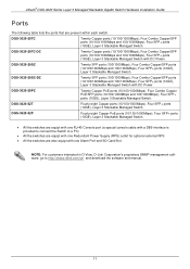
... Console port (a special console cable with a DB9 interface is provided to connect the Switch to http://dview.dlink.com.tw/ and download the software and manual. 11 DGS-3620-28SC Twenty SFP ports (100/1000Mbps), Four Combo Copper/SFP ports (10/100/1000Mbps and 100/1000Mbps), Four SFP+ ports (10GE), Layer 3 Stackable Managed Switch. NOTE: For customers interested in D-View, D-Link Corporation's proprietary SNMP management software, go to a PC) • All the switches are equipt with one Redundant Power Supply...
... Console port (a special console cable with a DB9 interface is provided to connect the Switch to http://dview.dlink.com.tw/ and download the software and manual. 11 DGS-3620-28SC Twenty SFP ports (100/1000Mbps), Four Combo Copper/SFP ports (10/100/1000Mbps and 100/1000Mbps), Four SFP+ ports (10GE), Layer 3 Stackable Managed Switch. NOTE: For customers interested in D-View, D-Link Corporation's proprietary SNMP management software, go to a PC) • All the switches are equipt with one Redundant Power Supply...
Hardware Installation Guide
Page 13
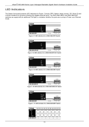
... LED indicators for a DGS-3620-28TC-DC Switch Figure 1-9 LED indicators for a DGS-3620-28SC Switch Figure 1-10 LED indicators for a DGS-3620-28SC-DC Switch Figure 1-11 LED indicators for all ports including the Gigabit Ethernet ports. xStack® DGS-3620 Series Layer 3 Managed Stackable Gigabit Switch Hardware Installation Guide LED Indicators The Switch front panel presents LED indicators for Power, Console, RPS, Master (stack control), SD, Stack ID and Link/Act indicators for a DGS-3620-28PC Switch 13 The DGS-3620-28PC and DGS-3620-52P switches are equipt with an additional PoE light...
... LED indicators for a DGS-3620-28TC-DC Switch Figure 1-9 LED indicators for a DGS-3620-28SC Switch Figure 1-10 LED indicators for a DGS-3620-28SC-DC Switch Figure 1-11 LED indicators for all ports including the Gigabit Ethernet ports. xStack® DGS-3620 Series Layer 3 Managed Stackable Gigabit Switch Hardware Installation Guide LED Indicators The Switch front panel presents LED indicators for Power, Console, RPS, Master (stack control), SD, Stack ID and Link/Act indicators for a DGS-3620-28PC Switch 13 The DGS-3620-28PC and DGS-3620-52P switches are equipt with an additional PoE light...
Hardware Installation Guide
Page 14
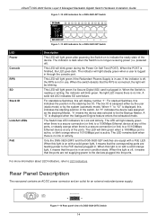
...; DGS-3620 Series Layer 3 Managed Stackable Gigabit Switch Hardware Installation Guide Figure 1-12 LED indicators for a DGS-3620-52T Switch Figure 1-13 LED indicators for a DGS-3620-52P Switch LED Power Console RPS SD Stack ID Link/Act LEDs PoE Description This LED will light green if the Redundant Powers Supply is in use . The LED will blink green during the Power-On Self Test (POST). When this will blink green. For more information about LED Indicators, refer to the devices plugged into the ports. This LED will blink green when a 1000Mbps port is...
...; DGS-3620 Series Layer 3 Managed Stackable Gigabit Switch Hardware Installation Guide Figure 1-12 LED indicators for a DGS-3620-52T Switch Figure 1-13 LED indicators for a DGS-3620-52P Switch LED Power Console RPS SD Stack ID Link/Act LEDs PoE Description This LED will light green if the Redundant Powers Supply is in use . The LED will blink green during the Power-On Self Test (POST). When this will blink green. For more information about LED Indicators, refer to the devices plugged into the ports. This LED will blink green when a 1000Mbps port is...

Hardware Installation Guide
Page 18
... the Switch. xStack® DGS-3620 Series Layer 3 Managed Stackable Gigabit Switch Hardware Installation Guide Chapter 2 Installation Package Contents Installation Guidelines Power On (AC Power) Alarm Connector Installing SFP and SFP+ Ports Connecting to the AC power port. • Make sure that it from scratching other surfaces. 18 The carton should be within 1.82 meters (6 feet) of the device. Installation Guidelines Please follow these guidelines for setting up the Switch: • Install the Switch on the type of...
... the Switch. xStack® DGS-3620 Series Layer 3 Managed Stackable Gigabit Switch Hardware Installation Guide Chapter 2 Installation Package Contents Installation Guidelines Power On (AC Power) Alarm Connector Installing SFP and SFP+ Ports Connecting to the AC power port. • Make sure that it from scratching other surfaces. 18 The carton should be within 1.82 meters (6 feet) of the device. Installation Guidelines Please follow these guidelines for setting up the Switch: • Install the Switch on the type of...

Hardware Installation Guide
Page 28
... Link LED turns green when a connection is made. The fiber-optic ports can connect to the Gigabit Ethernet ports using a fiber-optic cable or a Category 5E copper cable, depending on a switch with a straight or crossover cable Connect to a Network Backbone or Server The combo SFP ports and the 1000BASE-T ports are ideal for uplinking to a network backbone, server or server farm. The copper ports operate at both 100Mbps and 1000Mbps in half or full duplex mode. xStack® DGS-3620 Series Layer 3 Managed Stackable Gigabit Switch Hardware Installation Guide Figure 3-2 Connect...
... Link LED turns green when a connection is made. The fiber-optic ports can connect to the Gigabit Ethernet ports using a fiber-optic cable or a Category 5E copper cable, depending on a switch with a straight or crossover cable Connect to a Network Backbone or Server The combo SFP ports and the 1000BASE-T ports are ideal for uplinking to a network backbone, server or server farm. The copper ports operate at both 100Mbps and 1000Mbps in half or full duplex mode. xStack® DGS-3620 Series Layer 3 Managed Stackable Gigabit Switch Hardware Installation Guide Figure 3-2 Connect...
Hardware Installation Guide
Page 29
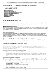
... software then insert the RJ-45 connector into the RJ-45 console port on the front panel or in the database. Command Line Interface Management through the console port on the front of the switch. This cable should be managed out-of the DGS-3620 Series. xStack® DGS-3620 Series Layer 3 Managed Stackable Gigabit Switch Hardware Installation Guide Chapter 4 Introduction to Switch Management Management Options Connecting the Console Port Connecting to the Switch for the First Time Connecting to the Management Port Password Protection Assigning IP Addresses SNMP Settings Management...
... software then insert the RJ-45 connector into the RJ-45 console port on the front panel or in the database. Command Line Interface Management through the console port on the front of the switch. This cable should be managed out-of the DGS-3620 Series. xStack® DGS-3620 Series Layer 3 Managed Stackable Gigabit Switch Hardware Installation Guide Chapter 4 Introduction to Switch Management Management Options Connecting the Console Port Connecting to the Switch for the First Time Connecting to the Management Port Password Protection Assigning IP Addresses SNMP Settings Management...
Hardware Installation Guide
Page 30
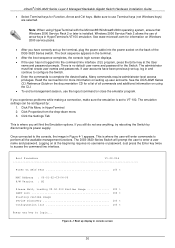
... menu 3. Once connected to VT-100. xStack® DGS-3620 Series Layer 3 Managed Stackable Gigabit Switch Hardware Installation Guide • Select Terminal keys for the Switch. See www.microsoft.com for more information on at the User name and password prompts. If user accounts have correctly set up , log in the terminal. • After the boot sequence completes, the console login screen displays. • If the user has not logged into the power socket on using HyperTerminal with...
... menu 3. Once connected to VT-100. xStack® DGS-3620 Series Layer 3 Managed Stackable Gigabit Switch Hardware Installation Guide • Select Terminal keys for the Switch. See www.microsoft.com for more information on at the User name and password prompts. If user accounts have correctly set up , log in the terminal. • After the boot sequence completes, the console login screen displays. • If the user has not logged into the power socket on using HyperTerminal with...
Hardware Installation Guide
Page 31
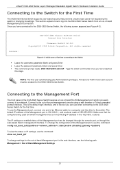
... time connecting to the switch. NOTE: The first user automatically gets Administrative privileges. To use the Management port, connect one Admin-level user account must be changed through the console port, or through the web-based Switch management interface. The default IP address of the Management port is the tool you have connected to the out-of-bound management console using a web browser or Telnet command prompt interface. The IP settings or enabled status of the Management port can easily connect to the DGS-3620 Series Switch for the DGS-3620 Series Switch. Connect...
... time connecting to the switch. NOTE: The first user automatically gets Administrative privileges. To use the Management port, connect one Admin-level user account must be changed through the console port, or through the web-based Switch management interface. The default IP address of the Management port is the tool you have connected to the out-of-bound management console using a web browser or Telnet command prompt interface. The IP settings or enabled status of the Management port can easily connect to the DGS-3620 Series Switch for the DGS-3620 Series Switch. Connect...
Hardware Installation Guide
Page 32
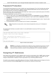
... your configuration changes in length. Once entered, the Switch will then prompt the user to the Switch's management software. Type the same password and press the Enter key. 4. prompt appears. The sample below . 32 DGS-3620-28SC:admin# Figure 4-3 Create account command NOTICE: CLI configuration commands only modify the running configuration file to create user accounts. To save command to copy the running configuration file and are case sensitive. Assigning IP Addresses Each Switch must use the save all your networking address...
... your configuration changes in length. Once entered, the Switch will then prompt the user to the Switch's management software. Type the same password and press the Enter key. 4. prompt appears. The sample below . 32 DGS-3620-28SC:admin# Figure 4-3 Create account command NOTICE: CLI configuration commands only modify the running configuration file to create user accounts. To save command to copy the running configuration file and are case sensitive. Assigning IP Addresses Each Switch must use the save all your networking address...
Hardware Installation Guide
Page 33
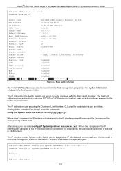
... manager. DGS-3620-28SC:admin# 33 The IP address for the Switch must be used to connect a management station to the IP interface named System and the y's represent the corresponding subnet mask. Where the x's represent the IP address to be assigned to the Switch's Telnet or Web-based management agent. The IP address may be set using the Command Line Interface (CLI) over the console serial port as follows: Starting at the command line prompt, enter the commands config...
... manager. DGS-3620-28SC:admin# 33 The IP address for the Switch must be used to connect a management station to the IP interface named System and the y's represent the corresponding subnet mask. Where the x's represent the IP address to be assigned to the Switch's Telnet or Web-based management agent. The IP address may be set using the Command Line Interface (CLI) over the console serial port as follows: Starting at the command line prompt, enter the commands config...
Hardware Installation Guide
Page 34
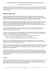
... network manager). An additional layer of security is separated into two parts. The SNMP version may be restricted from any station that the command was used to as an SNMP manager. The Switch generates traps and sends them to configure system features for the Switch used to set for SNMP v3 in the Switch, switch group or network. xStack® DGS-3620 Series Layer 3 Managed Stackable Gigabit Switch Hardware Installation Guide Figure 4-5 Assigning the Switch an IP Address In the above example...
... network manager). An additional layer of security is separated into two parts. The SNMP version may be restricted from any station that the command was used to as an SNMP manager. The Switch generates traps and sends them to configure system features for the Switch used to set for SNMP v3 in the Switch, switch group or network. xStack® DGS-3620 Series Layer 3 Managed Stackable Gigabit Switch Hardware Installation Guide Figure 4-5 Assigning the Switch an IP Address In the above example...
Hardware Installation Guide
Page 39
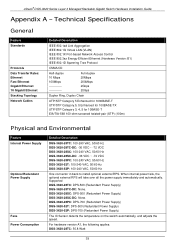
... the speed. For hardware version A1, the following applies: DGS-3620-28TC: 50.8 Watt 39 Supported DGS-3620-28TC: DPS-500 (Redundant Power Supply) DGS-3620-28TC-DC: None. xStack® DGS-3620 Series Layer 3 Managed Stackable Gigabit Switch Hardware Installation Guide Appendix A - Technical Specifications General Feature Standards Protocols Data Transfer Rates: Ethernet Fast Ethernet Gigabit Ethernet 10 Gigabit Ethernet Stacking Topology Network Cables Detailed Description IEEE 802.1ad Link Aggregation IEEE 802.1Q Virtual LAN (VLAN) IEEE 802.1X Port-based Network Access Control IEEE...
... the speed. For hardware version A1, the following applies: DGS-3620-28TC: 50.8 Watt 39 Supported DGS-3620-28TC: DPS-500 (Redundant Power Supply) DGS-3620-28TC-DC: None. xStack® DGS-3620 Series Layer 3 Managed Stackable Gigabit Switch Hardware Installation Guide Appendix A - Technical Specifications General Feature Standards Protocols Data Transfer Rates: Ethernet Fast Ethernet Gigabit Ethernet 10 Gigabit Ethernet Stacking Topology Network Cables Detailed Description IEEE 802.1ad Link Aggregation IEEE 802.1Q Virtual LAN (VLAN) IEEE 802.1X Port-based Network Access Control IEEE...
Hardware Installation Guide
Page 41
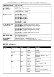
...; DGS-3620 Series Layer 3 Managed Stackable Gigabit Switch Hardware Installation Guide Transmission Method Packet Buffer Packet Filtering / Forwarding Rate Wire speed Switching Capacity 64 Byte System Packet Forwarding Rate Priority Queues MAC Address Table Virtual Stacking / Clustering Store-and-forward. 2 MBytes per port. Supports D-Link Single IP Management version 1.6. LED Indicators Location Per Device LED Indicative Power Console RPS Color Green Green Green SD MGMT Green Red Green Status Solid Light Light off Solid Light Light off Blinking Solid Light Light off Solid Light...
...; DGS-3620 Series Layer 3 Managed Stackable Gigabit Switch Hardware Installation Guide Transmission Method Packet Buffer Packet Filtering / Forwarding Rate Wire speed Switching Capacity 64 Byte System Packet Forwarding Rate Priority Queues MAC Address Table Virtual Stacking / Clustering Store-and-forward. 2 MBytes per port. Supports D-Link Single IP Management version 1.6. LED Indicators Location Per Device LED Indicative Power Console RPS Color Green Green Green SD MGMT Green Red Green Status Solid Light Light off Solid Light Light off Blinking Solid Light Light off Solid Light...

Hardware Installation Guide
Page 42
... user (static mode) or by turn for all 10/100/1000Mbps ports on DGS-3620-28PC/52P: • Link/Act/Speed Mode • PoE Mode Green Solid Light A LED Mode Select Button to switch Link/Act/Speed Mode Solid Light A LED Mode Select Button to switch PoE Mode Green Solid Light When there is reception or transmission of data occurring at 10/100Mbps. xStack® DGS-3620 Series Layer 3 Managed Stackable Gigabit Switch Hardware Installation Guide Stacking ID Port LED Mode Indicator LED Per Link/Act/Speed 10/100/1000 Mbps Mode Port PoE Mode LED per SFP Port Link/Act Green Capable...
... user (static mode) or by turn for all 10/100/1000Mbps ports on DGS-3620-28PC/52P: • Link/Act/Speed Mode • PoE Mode Green Solid Light A LED Mode Select Button to switch Link/Act/Speed Mode Solid Light A LED Mode Select Button to switch PoE Mode Green Solid Light When there is reception or transmission of data occurring at 10/100Mbps. xStack® DGS-3620 Series Layer 3 Managed Stackable Gigabit Switch Hardware Installation Guide Stacking ID Port LED Mode Indicator LED Per Link/Act/Speed 10/100/1000 Mbps Mode Port PoE Mode LED per SFP Port Link/Act Green Capable...

Hardware Installation Guide
Page 44
.... Supports IEEE 802.3af PoE and IEEE 802.3at PoE+ compliance. 2. For 802.3af/at capable devices it will remain active. 6. Autotomatically disable ports if the port current is a short while other ports remain active. 7. xStack® DGS-3620 Series Layer 3 Managed Stackable Gigabit Switch Hardware Installation Guide SFP+ Ports • DEM-331T/R (1000BASE-BX, Single-Mode, 40km) Compliant with the following classifications below: Class Usage Max Power used by PD 0 Default 12...
.... Supports IEEE 802.3af PoE and IEEE 802.3at PoE+ compliance. 2. For 802.3af/at capable devices it will remain active. 6. Autotomatically disable ports if the port current is a short while other ports remain active. 7. xStack® DGS-3620 Series Layer 3 Managed Stackable Gigabit Switch Hardware Installation Guide SFP+ Ports • DEM-331T/R (1000BASE-BX, Single-Mode, 40km) Compliant with the following classifications below: Class Usage Max Power used by PD 0 Default 12...
Hardware Installation Guide
Page 48
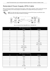
... +12V 4 +12V +12V 5 +12V +12V 6 +12V +12V 7 NC/GND NC/GND 48 Figure B-3 Redundant Power Supply (RPS) Cable - Please review these products for matching cable pins.The following diagrams and tables show the standard RPS connector and their own cables included in the package. xStack® DGS-3620 Series Layer 3 Managed Stackable Gigabit Switch Hardware Installation Guide Redundant Power Supply (RPS) Cable When connecting the Switch to a Redundant Power Supply, an RPS cable is necessary.
... +12V 4 +12V +12V 5 +12V +12V 6 +12V +12V 7 NC/GND NC/GND 48 Figure B-3 Redundant Power Supply (RPS) Cable - Please review these products for matching cable pins.The following diagrams and tables show the standard RPS connector and their own cables included in the package. xStack® DGS-3620 Series Layer 3 Managed Stackable Gigabit Switch Hardware Installation Guide Redundant Power Supply (RPS) Cable When connecting the Switch to a Redundant Power Supply, an RPS cable is necessary.


