
Configuration Guide
Page 1
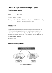
... networks. Please visit the UK ftp site for the latest firmware releases. ftp://ftp.dlink.co.uk Network Configuration Fig 1. Introduction This guide will help you to setup a routing function to have the latest firmware installed in the switch before embarking on the configuration. At the time of writing this document the firmware release was 1.00B19. Network Configuration. DES-3326 Layer 3 Switch Example Layer 3 Configuration Guide. Model: DES-3326 Firmware Version 1.00B19 OS Supported: Windows 95, Windows 98, Windows 98SE, Windows Me, Windows NT 4.0 and Windows...
... networks. Please visit the UK ftp site for the latest firmware releases. ftp://ftp.dlink.co.uk Network Configuration Fig 1. Introduction This guide will help you to setup a routing function to have the latest firmware installed in the switch before embarking on the configuration. At the time of writing this document the firmware release was 1.00B19. Network Configuration. DES-3326 Layer 3 Switch Example Layer 3 Configuration Guide. Model: DES-3326 Firmware Version 1.00B19 OS Supported: Windows 95, Windows 98, Windows 98SE, Windows Me, Windows NT 4.0 and Windows...

Configuration Guide
Page 2
... configuration is on ports 17 to the switch through its RS232 console port with HyperTerminal and login onto the switch. Fig 2. Fig 2. For the purpose of this , attach to 24. An illustration of a typical layer 3 application is layer 2. above . To do this document, fig 1. Two departments are segmented using layer 3 routing protocol rather than segmented at the MAC layer. Mix of routing between the 2 subnets. The default setting...
... configuration is on ports 17 to the switch through its RS232 console port with HyperTerminal and login onto the switch. Fig 2. Fig 2. For the purpose of this , attach to 24. An illustration of a typical layer 3 application is layer 2. above . To do this document, fig 1. Two departments are segmented using layer 3 routing protocol rather than segmented at the MAC layer. Mix of routing between the 2 subnets. The default setting...
Configuration Guide
Page 3
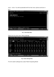
You will be presented with the main menu options as shown in fig 3. Fig 3. Switch Main Menu Select from the main menu 'Switch Settings' Fig 4. Switch Settings Menu From the switch settings menu select 'Switch Operating Mode' return. return -
You will be presented with the main menu options as shown in fig 3. Fig 3. Switch Main Menu Select from the main menu 'Switch Settings' Fig 4. Switch Settings Menu From the switch settings menu select 'Switch Operating Mode' return. return -
Configuration Guide
Page 4
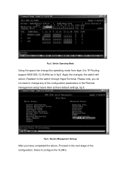
Please note, you have completed the above. Proceed to the next stage of the configuration, that is to change the operating mode from layer 2 to the switch through HyperTerminal. Switch Operating Mode Using the space bar change any of the configuration parameters in fig 5. Fig 6. Reattach to 'IP Routing, support IEEE 802.1Q VLANs' as in the 'Remote management setup' leave them at there default settings, fig 6. Remote Management Settings After you do not need to configure the VLAN's. Fig 5. Apply the changes, the switch will reboot.
Please note, you have completed the above. Proceed to the next stage of the configuration, that is to change the operating mode from layer 2 to the switch through HyperTerminal. Switch Operating Mode Using the space bar change any of the configuration parameters in fig 5. Fig 6. Reattach to 'IP Routing, support IEEE 802.1Q VLANs' as in the 'Remote management setup' leave them at there default settings, fig 6. Remote Management Settings After you do not need to configure the VLAN's. Fig 5. Apply the changes, the switch will reboot.
Configuration Guide
Page 5
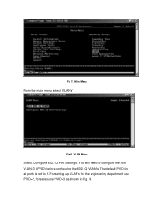
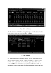
Fig 7. The default PVID for sales use PVID=2, for all ports is set to configure the port VLAN ID (PVID) before configuring the 802.1Q VLAN's. For setting up VLAN's for the engineering department use PVID=3 as shown in Fig. 9. VLAN Menu Select 'Configure 802.1Q Port Settings'. Main Menu From the main menu select 'VLAN's' Fig 8. You will need to 1.
Fig 7. The default PVID for sales use PVID=2, for all ports is set to configure the port VLAN ID (PVID) before configuring the 802.1Q VLAN's. For setting up VLAN's for the engineering department use PVID=3 as shown in Fig. 9. VLAN Menu Select 'Configure 802.1Q Port Settings'. Main Menu From the main menu select 'VLAN's' Fig 8. You will need to 1.
Configuration Guide
Page 6
Fig 9. 802.1Q Port Settings After the above is , ie do not change the default VID. You will need to VLAN name and enter an appropriate name. In this example we have the first octet of the IP adress. Fig 10. 802.1Q VLAN's For the VID use the TAB key to cursor to leave the default VLAN as used for the PVID previously. Under the membership, 'Egress' the port Use the TAB key to cursor to the VID and enter '2', again use the same number as is completed your ready to the previous menu and select 'Edit 802.1.Q VLAN's'. Go to configure the 802.1Q VLAN's.
Fig 9. 802.1Q Port Settings After the above is , ie do not change the default VID. You will need to VLAN name and enter an appropriate name. In this example we have the first octet of the IP adress. Fig 10. 802.1Q VLAN's For the VID use the TAB key to cursor to leave the default VLAN as used for the PVID previously. Under the membership, 'Egress' the port Use the TAB key to cursor to the VID and enter '2', again use the same number as is completed your ready to the previous menu and select 'Edit 802.1.Q VLAN's'. Go to configure the 802.1Q VLAN's.

Configuration Guide
Page 7
You will need to Egress all the port members of this example only ports 1 & 2 are members. In this VLAN. This is so because adapters connected to configure you layer 3 routing configuration within the switch. Your now ready to these ports may not be Tag compliant. Layer 3 IP Networking Fig 12. In the Tagging section, select 'U' for the second subnet. From the main menu select layer 3 IP Networking, then select 'Setup IP Interface' Fig 11. by selecting E. IP Interface Setup Repeat the procedure for Untag.
You will need to Egress all the port members of this example only ports 1 & 2 are members. In this VLAN. This is so because adapters connected to configure you layer 3 routing configuration within the switch. Your now ready to these ports may not be Tag compliant. Layer 3 IP Networking Fig 12. In the Tagging section, select 'U' for the second subnet. From the main menu select layer 3 IP Networking, then select 'Setup IP Interface' Fig 11. by selecting E. IP Interface Setup Repeat the procedure for Untag.

Configuration Guide
Page 8
After the config is the PVID set in fig 12. Subnet 192 Config Fig 14. The VID is applied, the screen will show you the configuration as in the VLAN configuration previously done. If all the configurations have choosen 192.168.0.250 MASK 255.255.255.0. Fig 13. The IP address is the IP address of the the switch in this example we have been applied, check the IP interfaces addresses. Subnet 212 Config Ensure all looks okay return to the main menu and save the configuration. Once again in that particular subnet, we have used the fist octet for the interface name.
After the config is the PVID set in fig 12. Subnet 192 Config Fig 14. The VID is applied, the screen will show you the configuration as in the VLAN configuration previously done. If all the configurations have choosen 192.168.0.250 MASK 255.255.255.0. Fig 13. The IP address is the IP address of the the switch in this example we have been applied, check the IP interfaces addresses. Subnet 212 Config Ensure all looks okay return to the main menu and save the configuration. Once again in that particular subnet, we have used the fist octet for the interface name.
Configuration Guide
Page 9
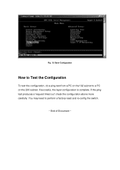
If succesful, the layer configuration is complete. If the ping test produces a 'request timed out' check the configuration above more carefully. Fig. 15 Save Configuration How to Test the Configuration To test the configuration, do a ping test from a PC on the 192 subnet to perform a factory reset and re-config the switch. ~ End of Document ~ You may need to a PC on the 200 subnet.
If succesful, the layer configuration is complete. If the ping test produces a 'request timed out' check the configuration above more carefully. Fig. 15 Save Configuration How to Test the Configuration To test the configuration, do a ping test from a PC on the 192 subnet to perform a factory reset and re-config the switch. ~ End of Document ~ You may need to a PC on the 200 subnet.


