Instruction Manual
Page 3
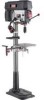
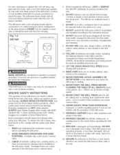
...8=1/4" 8=1/2" 68=1/2" 12 =3/4" 28-1/2" 198 pounds Yes Yes To avoid electrical shock to yourself and damage to the drill press, use proper circuit protection, Do not expose to rain, or use in a damp environment, The drill press is factory wired for 120V, 60 Hz, operation, Connect to a 120V, 15 amp branch circuit and use ...a 15 amp time delay fuse or circuit breaker, The electrical circuit cannot have any way, 17°in any wire size less than #14,...
...8=1/4" 8=1/2" 68=1/2" 12 =3/4" 28-1/2" 198 pounds Yes Yes To avoid electrical shock to yourself and damage to the drill press, use proper circuit protection, Do not expose to rain, or use in a damp environment, The drill press is factory wired for 120V, 60 Hz, operation, Connect to a 120V, 15 amp branch circuit and use ...a 15 amp time delay fuse or circuit breaker, The electrical circuit cannot have any way, 17°in any wire size less than #14,...
Instruction Manual
Page 4
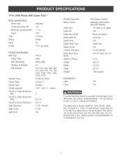
...and common sense are ignored, The operator must be familiar with the operation of the tool, Read this manual to understand this drill press, DO NOT operate this drill press if you accidentally contact the tool, 13, DO NOT store anything above or near the tool where anyone might try to ...used to ground the tool and provide protection against accidental electric shock, DO NOT remove the 3rd prong, See Grounding instructions, 17, KEEP VISITORS AND CHILDREN AWAY from the drill press, DO NOT permit people to be immediately repaired or replaced, 16, GROUND ALL TOOLS, if the tool is supplied with...
...and common sense are ignored, The operator must be familiar with the operation of the tool, Read this manual to understand this drill press, DO NOT operate this drill press if you accidentally contact the tool, 13, DO NOT store anything above or near the tool where anyone might try to ...used to ground the tool and provide protection against accidental electric shock, DO NOT remove the 3rd prong, See Grounding instructions, 17, KEEP VISITORS AND CHILDREN AWAY from the drill press, DO NOT permit people to be immediately repaired or replaced, 16, GROUND ALL TOOLS, if the tool is supplied with...
Instruction Manual
Page 6
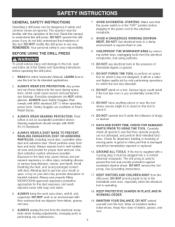
... cover. If a properly grounded electrical receptacle is necessary. CAUTION: In all cases, make certain the electrical receptacle in accordance with your Drill Press is a dual voltage 120/240 volts, 60 hertz alternating current, single phase motor, It is shipped wired for 120 volts application, ... 120/240 volt, single phase motor. THIS ADAPTER IS PROHIBITED IN CANADA. The conductor with the green insulation (with your Drill Press is desired to operate your drill press at 240 volts, it that MUST be used to temporarily connect this plug to a permanent earth ground, such as shown ...
... cover. If a properly grounded electrical receptacle is necessary. CAUTION: In all cases, make certain the electrical receptacle in accordance with your Drill Press is a dual voltage 120/240 volts, 60 hertz alternating current, single phase motor, It is shipped wired for 120 volts application, ... 120/240 volt, single phase motor. THIS ADAPTER IS PROHIBITED IN CANADA. The conductor with the green insulation (with your Drill Press is desired to operate your drill press at 240 volts, it that MUST be used to temporarily connect this plug to a permanent earth ground, such as shown ...
Instruction Manual
Page 7
... all electrical and safety codes, including the National Electric Code (NEC) and the Occupational Safety and Health Regulations (OSHA). Unplug the drill press from the outlet when not in use and before installing in debris being thrown into the ebctrical outlet. Debris can throw debris during... (fly) cutters, rotary planers or wire wheels in this drill press, 17, PROPERLY SUPPORT long or wide workpiece and clamp to the table, 18, PROPERLY SECURE the drill bit, cutting tool, or sanding drum in the chuck before operating the drill press, 19, REPLACE a damaged cord immediately, DO NOT use ...
... all electrical and safety codes, including the National Electric Code (NEC) and the Occupational Safety and Health Regulations (OSHA). Unplug the drill press from the outlet when not in use and before installing in debris being thrown into the ebctrical outlet. Debris can throw debris during... (fly) cutters, rotary planers or wire wheels in this drill press, 17, PROPERLY SUPPORT long or wide workpiece and clamp to the table, 18, PROPERLY SECURE the drill bit, cutting tool, or sanding drum in the chuck before operating the drill press, 19, REPLACE a damaged cord immediately, DO NOT use ...
Instruction Manual
Page 8
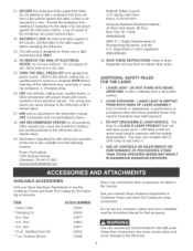
... for this manual, See your nearest Sears Hardware Department or Craftsman Power and Hand Tool Catalog for other accessories, Do not use any accessory unless you have completely read the instruction Manual for that can emit laser power up to the drill press, DO NOT STARE INTO BEAM, APERTURE, or into a reflection from...
... for this manual, See your nearest Sears Hardware Department or Craftsman Power and Hand Tool Catalog for other accessories, Do not use any accessory unless you have completely read the instruction Manual for that can emit laser power up to the drill press, DO NOT STARE INTO BEAM, APERTURE, or into a reflection from...
Instruction Manual
Page 10
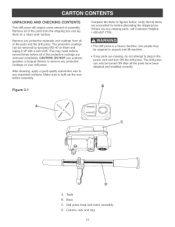
...required to unpack and lift machine, if any parts are missing, do not attempt to plug in the power cord and turn ON the drill press, The drill press can only be removed by spraying WD-40 on them on your drHUpress, After cleaning, apply a good quality automotive wax to any ... and the drHUpress, The protective coatings can be turned ON after all the parts have been obtained and installed correctly, B } A, Table B, Base C, Drill press head and motor assembly D, Column, rack and ring 10 UNPACKUNG AND CHECKUNG CONTENTS This drHUpress wHUrequire some amount of assemMy, Remove aH of the parts...
...required to unpack and lift machine, if any parts are missing, do not attempt to plug in the power cord and turn ON the drill press, The drill press can only be removed by spraying WD-40 on them on your drHUpress, After cleaning, apply a good quality automotive wax to any ... and the drHUpress, The protective coatings can be turned ON after all the parts have been obtained and installed correctly, B } A, Table B, Base C, Drill press head and motor assembly D, Column, rack and ring 10 UNPACKUNG AND CHECKUNG CONTENTS This drHUpress wHUrequire some amount of assemMy, Remove aH of the parts...
Instruction Manual
Page 14
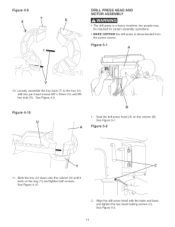
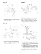
two peopb may be required for certain assemMy operations, MAKE CERTAIN the drHUpress is a heavy machine; Figure 4-9 T X \ DRILL PRESS HEAD AND MOTOR ASSEMBLY The drHUpress is disconnected from the power source, Figure 5-1 A V 10, LooseUy assembb the tray back (T) to the tray (U) with two pan ... Figure 5-1, Figure 5-2 11, Slide the tray (U) down onto the column (A) until it rests on the ring (Y) and tighten both screws, See Figure 4-10 2, Align the drill press head with the table and base and tighten the two head locking screws (C), See Figure 5-2, 14
two peopb may be required for certain assemMy operations, MAKE CERTAIN the drHUpress is a heavy machine; Figure 4-9 T X \ DRILL PRESS HEAD AND MOTOR ASSEMBLY The drHUpress is disconnected from the power source, Figure 5-1 A V 10, LooseUy assembb the tray back (T) to the tray (U) with two pan ... Figure 5-1, Figure 5-2 11, Slide the tray (U) down onto the column (A) until it rests on the ring (Y) and tighten both screws, See Figure 4-10 2, Align the drill press head with the table and base and tighten the two head locking screws (C), See Figure 5-2, 14
Instruction Manual
Page 15
... collar (I) and turn the chuck barrel (J) counter-clockwise, Make sure the jaws are completely recessed inside the chuck, See figure 5-6, 6, Seat the chuck onto the drill press spindle as far as it wiii go, Carefully drive the chuck onto the spindle by placing a wooden block (K) under the chuck (L) and tap the block...
... collar (I) and turn the chuck barrel (J) counter-clockwise, Make sure the jaws are completely recessed inside the chuck, See figure 5-6, 6, Seat the chuck onto the drill press spindle as far as it wiii go, Carefully drive the chuck onto the spindle by placing a wooden block (K) under the chuck (L) and tap the block...
Instruction Manual
Page 16
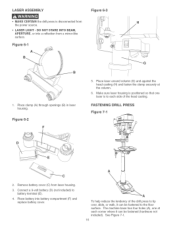
LASER ASSEMBLY MAKE CERTAIN the drill press is to battery terminal (E), 4, Place battery into a reflection from a mirrorqke surface, Figure 6-1 Figure 6-3 1, Place clamp (A) through openings (B) in laser housing, Figure 6-2 F 5, Hace Uaser around coUumn (G) ... power source, LASER LIGHT - DO NOT STARE INTO BEAM, APERTURE, or into battery compartment (F) and replace battery cover, A To help reduce the tendency of the drill press to tip over, slide, or walk, it can be fastened to the floor surface, The machine base has four hobs (A), one Uaser is disconnected from...
LASER ASSEMBLY MAKE CERTAIN the drill press is to battery terminal (E), 4, Place battery into a reflection from a mirrorqke surface, Figure 6-1 Figure 6-3 1, Place clamp (A) through openings (B) in laser housing, Figure 6-2 F 5, Hace Uaser around coUumn (G) ... power source, LASER LIGHT - DO NOT STARE INTO BEAM, APERTURE, or into battery compartment (F) and replace battery cover, A To help reduce the tendency of the drill press to tip over, slide, or walk, it can be fastened to the floor surface, The machine base has four hobs (A), one Uaser is disconnected from...
Instruction Manual
Page 17
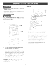
To use the Drill Press, unlock and remove the... get them, See Figure 8-2, 8. To turn the Drill Press off, press the large red OFF paddle (C) or lift the paddle and press directly on the red "OFF" button (D), See Figure... OFF position to insure that it cannot be completely pressed before the motor will start, 8. Using the padlock (E) included with your Drill Press, lift the red iOFF[ paddle (C) and place the...Note: There is a safety feature on , press the green ON button (B) in the side of the drill press head, See Figure 8-1, 2. When the Drill Press is not in use, the switch should be...
To use the Drill Press, unlock and remove the... get them, See Figure 8-2, 8. To turn the Drill Press off, press the large red OFF paddle (C) or lift the paddle and press directly on the red "OFF" button (D), See Figure... OFF position to insure that it cannot be completely pressed before the motor will start, 8. Using the padlock (E) included with your Drill Press, lift the red iOFF[ paddle (C) and place the...Note: There is a safety feature on , press the green ON button (B) in the side of the drill press head, See Figure 8-1, 2. When the Drill Press is not in use, the switch should be...
Instruction Manual
Page 18
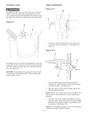
... lower the table (A) on the column (B), loosen the table lock handle (C), See Figure 10-1 and 10-2, Figure 10-2 A The flexible lamp (A) operates independently of the drill press and has its own power cord, To turn the lamp ON and OFF, rotate the switch (B) in the clockwise direction only, See Figure 9-1, CAUTION: The... loosening the table rotation lock handle (E) and rotating the table to the desired position, and tightening the table clamp, See Figure 10-2, NOTE: For thru-drilling operations, make sure the table center hob is aligned with the...
... lower the table (A) on the column (B), loosen the table lock handle (C), See Figure 10-1 and 10-2, Figure 10-2 A The flexible lamp (A) operates independently of the drill press and has its own power cord, To turn the lamp ON and OFF, rotate the switch (B) in the clockwise direction only, See Figure 9-1, CAUTION: The... loosening the table rotation lock handle (E) and rotating the table to the desired position, and tightening the table clamp, See Figure 10-2, NOTE: For thru-drilling operations, make sure the table center hob is aligned with the...
Instruction Manual
Page 19
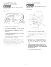
..., This will position the table surface 90 degrees to the spindle, The table locking bolt then must be tightened, MAKE CERTAIN the drill press is disconnected from the power source, Sixteen drill speeds (215, 310,340, 450, 490, 510, 600, 675,735, 750, 1200, 1380, 1500, 1850, 2035 and 2720 RPM) ... select the correct spindle speed for your operation, This diagram can also be found on the inside of the belt cover of the drill press, Figure 11-1 Recommended Dri|| Press Speeds 6P|H6LE PULLEY s ,o !so 00IdB0,d I,°00,dy,I0B 0I°.,.mIst001 600 TwisDt rillBits _45 1/1B"=3/1B" 2720 2720 ...
..., This will position the table surface 90 degrees to the spindle, The table locking bolt then must be tightened, MAKE CERTAIN the drill press is disconnected from the power source, Sixteen drill speeds (215, 310,340, 450, 490, 510, 600, 675,735, 750, 1200, 1380, 1500, 1850, 2035 and 2720 RPM) ... select the correct spindle speed for your operation, This diagram can also be found on the inside of the belt cover of the drill press, Figure 11-1 Recommended Dri|| Press Speeds 6P|H6LE PULLEY s ,o !so 00IdB0,d I,°00,dy,I0B 0I°.,.mIst001 600 TwisDt rillBits _45 1/1B"=3/1B" 2720 2720 ...
Instruction Manual
Page 20
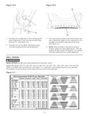
... line midway between the puHHeysusing Hightfinger pressure, 6, Tighten both tension lock knobs, A C D 1, Insert the drill bit into the chuck and tighten, 2, Place the workpiece on the drill press table, Raise the drill press table until the workpiece is 1/8-in, from the drill bit, NOTE: Make sure the workpiece is secured to the table properly, 3, Turn the...
... line midway between the puHHeysusing Hightfinger pressure, 6, Tighten both tension lock knobs, A C D 1, Insert the drill bit into the chuck and tighten, 2, Place the workpiece on the drill press table, Raise the drill press table until the workpiece is 1/8-in, from the drill bit, NOTE: Make sure the workpiece is secured to the table properly, 3, Turn the...
Instruction Manual
Page 21
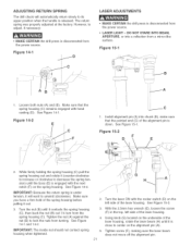
... its upper position when the handHe is reHeased, The return spring was properHy adjusted at the factory, However, to adjust, if necessary: ,, MAKE CERTAIN the drill press is disconnected from the power source, Figure 14-1 LASER ADJUSTMENTS ,, MAKE CERTAIN the drHHpress is disconnected from a mirror-Hike surface, Figure 15-1 A 1, Loosen both nuts...
... its upper position when the handHe is reHeased, The return spring was properHy adjusted at the factory, However, to adjust, if necessary: ,, MAKE CERTAIN the drill press is disconnected from the power source, Figure 14-1 LASER ADJUSTMENTS ,, MAKE CERTAIN the drHHpress is disconnected from a mirror-Hike surface, Figure 15-1 A 1, Loosen both nuts...
Instruction Manual
Page 22
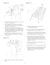
... so that it is about 1" under the alignment pin, 12, Lay a 3/4" piece of wood (M) onto the drill press table under the line pin, See Figure 15-5, 13, Using the drift press feed handle, lower the alignment pin down and mark (N) the wood, Make sure the wood does not move, See Figure 15-5, 14..., Tighten screw, making sure the laser beam does not move off the mark, 16, Repeat STEPS 14 and 15 to set the right side laser, 17, Move the wood about 1" and mark it again, checking that the mark is position where the two laser beams cross, if it does not repeat...
... so that it is about 1" under the alignment pin, 12, Lay a 3/4" piece of wood (M) onto the drill press table under the line pin, See Figure 15-5, 13, Using the drift press feed handle, lower the alignment pin down and mark (N) the wood, Make sure the wood does not move, See Figure 15-5, 14..., Tighten screw, making sure the laser beam does not move off the mark, 16, Repeat STEPS 14 and 15 to set the right side laser, 17, Move the wood about 1" and mark it again, checking that the mark is position where the two laser beams cross, if it does not repeat...
Instruction Manual
Page 23
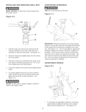
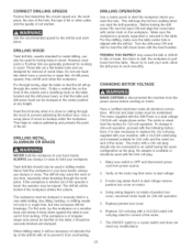
... it must be properly supported or clamped. Figure 18-1 SUPPORTING WOF{KPIECE USE onUyrecommended accessories. See Figure 16-1. NEVER run drill press to install or tighten a drill bit or cutter in the chuck as far as it from the power source. See figure 16-1. 2, Open the chuck jaws... the outward away from rotating. Figure 17-1 B o A HoUdthe collar (A) and turn the chuck barreU (B) counterocbckwbe to close the chuck jaws and clockwise to keep it wHUgo, and then back the bit out 1/16" (or up to prevent the workpiece from the drill press (C), See Figure 18-1, 23 See ...
... it must be properly supported or clamped. Figure 18-1 SUPPORTING WOF{KPIECE USE onUyrecommended accessories. See Figure 16-1. NEVER run drill press to install or tighten a drill bit or cutter in the chuck as far as it from the power source. See figure 16-1. 2, Open the chuck jaws... the outward away from rotating. Figure 17-1 B o A HoUdthe collar (A) and turn the chuck barreU (B) counterocbckwbe to close the chuck jaws and clockwise to keep it wHUgo, and then back the bit out 1/16" (or up to prevent the workpiece from the drill press (C), See Figure 18-1, 23 See ...
Instruction Manual
Page 25
...at any time, especially when breaking through the workpiece, if the workpiece is wired from walking when you want the hob. allow the drill press to work at any modifications. 25 However, brad point or Forstner bits are designed for removai of the operator's hand, the operator ... operation, 5. This will Hft and rotate the workpiece. Make sure the workpiece is dual voltage. 3. Verify on the table bracket and the drill press head, so that motor is properly supported or secured to prevent splintering the bottom face. Feed the bit slowly when it from power source, ...
...at any time, especially when breaking through the workpiece, if the workpiece is wired from walking when you want the hob. allow the drill press to work at any modifications. 25 However, brad point or Forstner bits are designed for removai of the operator's hand, the operator ... operation, 5. This will Hft and rotate the workpiece. Make sure the workpiece is dual voltage. 3. Verify on the table bracket and the drill press head, so that motor is properly supported or secured to prevent splintering the bottom face. Feed the bit slowly when it from power source, ...
Instruction Manual
Page 26
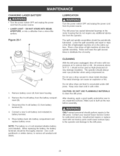
...of light machine oil down the spindle assembly, Raise and lower the quill several times to the drill press, 26 Use a soft paintbrush or similar device, to clean the drill press. With the drill press unplugged, blow off motor with non-factory parts could cause serious injury to the operator and damage... compartment and replace battery cover. CHANGmNG LASER BATTERY Turn the power switch OFF and unplug the power cord from its power source, The drill press has sealed lubricated bearings in safe order, CAUTION: DO NOT USE FLAMMABLE MATERIALS to remove all sawdust and debris. Connect a new 9-...
...of light machine oil down the spindle assembly, Raise and lower the quill several times to the drill press, 26 Use a soft paintbrush or similar device, to clean the drill press. With the drill press unplugged, blow off motor with non-factory parts could cause serious injury to the operator and damage... compartment and replace battery cover. CHANGmNG LASER BATTERY Turn the power switch OFF and unplug the power cord from its power source, The drill press has sealed lubricated bearings in safe order, CAUTION: DO NOT USE FLAMMABLE MATERIALS to remove all sawdust and debris. Connect a new 9-...
Instruction Manual
Page 27
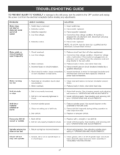
...belt tension. Chips not exiting out of spindle taper and chuck taper. Replace or sharpen drill bit. 1. Grease, dirt or oil on spindle taper or in "ASSEMBLY iNSTRUCTiONS". 27 See drill press head and motor assembly in chuck taper. 1. Have correct fuses on motor, slow down... feed rate. 4. Check all power lead connections. incorrect spindle speed. 2. Correct low line voltage condition. install drill bit properly. Adjust spring tension. Have...
...belt tension. Chips not exiting out of spindle taper and chuck taper. Replace or sharpen drill bit. 1. Grease, dirt or oil on spindle taper or in "ASSEMBLY iNSTRUCTiONS". 27 See drill press head and motor assembly in chuck taper. 1. Have correct fuses on motor, slow down... feed rate. 4. Check all power lead connections. incorrect spindle speed. 2. Correct low line voltage condition. install drill bit properly. Adjust spring tension. Have...
Instruction Manual
Page 29
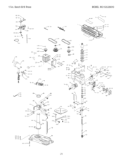
17-in. Bench Drill Press {50 (2_. 151 (6)_ 158--_ # 155 (2)_ _g I_158 45 (2) /141 _/ 140 MODEL N0.152.229010 _5 (4) i 119 (2) 112 114 -% \49 (2) 52 / 103 (4}_ 102 (4)_ i01 {g)_ 29
17-in. Bench Drill Press {50 (2_. 151 (6)_ 158--_ # 155 (2)_ _g I_158 45 (2) /141 _/ 140 MODEL N0.152.229010 _5 (4) i 119 (2) 112 114 -% \49 (2) 52 / 103 (4}_ 102 (4)_ i01 {g)_ 29

