Instruction Manual
Page 2
... warranty gives you specific legal rights, and you may also have other rights, which vary from state to state, Sears, Roebuck and Co,, Dept 817WA, Hoffman Estates, IL 60179 Service Information ... SECTmON PAGE Warranty...2 ProductSpecification.s...3 Safetymnstruction.s...4 Guidelinesfor extension cords ... 5 Grounding mnstructions ... 6 Specific Safety mnstructions ... 7 Accessories and Attachments ... 8 Know Your Machine ... 9 Carton Contents ... 10 AssembJy mnstructions ... 12 Operations and Adjustment ... 17 Maintenance ... 26 Troubleshooting Guide ... 27 Part List...
... warranty gives you specific legal rights, and you may also have other rights, which vary from state to state, Sears, Roebuck and Co,, Dept 817WA, Hoffman Estates, IL 60179 Service Information ... SECTmON PAGE Warranty...2 ProductSpecification.s...3 Safetymnstruction.s...4 Guidelinesfor extension cords ... 5 Grounding mnstructions ... 6 Specific Safety mnstructions ... 7 Accessories and Attachments ... 8 Know Your Machine ... 9 Carton Contents ... 10 AssembJy mnstructions ... 12 Operations and Adjustment ... 17 Maintenance ... 26 Troubleshooting Guide ... 27 Part List...
Instruction Manual
Page 3
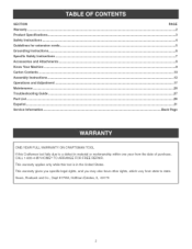
... avoid shock or fire, replace power cord immediately if it is damaged in . Drill Press with Laser°Trac TM Motor Specifications: Motor type Continuous duty HP Maximum developedHP Amps Volts Phase Hertz R,P,M, induction 3/4 1=1/2 10/5 120/240 Single 60 1725 (no load) Product Specifications: Belt Type Pulley Type Number of Speeds Drill Speeds Spindle Taper Chuck Taper Chuck Type Chuck capacity Chuck to Table dimension Min, Chuck to Table dimension Max, Chuck to Base dimension Quill Diameter Quill Travel Quill Lock Poly=V Step Motor slide 16 215, 310...
... avoid shock or fire, replace power cord immediately if it is damaged in . Drill Press with Laser°Trac TM Motor Specifications: Motor type Continuous duty HP Maximum developedHP Amps Volts Phase Hertz R,P,M, induction 3/4 1=1/2 10/5 120/240 Single 60 1725 (no load) Product Specifications: Belt Type Pulley Type Number of Speeds Drill Speeds Spindle Taper Chuck Taper Chuck Type Chuck capacity Chuck to Table dimension Min, Chuck to Table dimension Max, Chuck to Base dimension Quill Diameter Quill Travel Quill Lock Poly=V Step Motor slide 16 215, 310...
Instruction Manual
Page 4
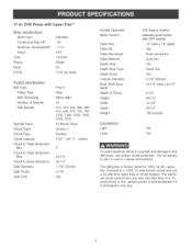
... accidental electric shock, DO NOT remove the 3rd prong, See Grounding instructions, 17, KEEP VISITORS AND CHILDREN AWAY from the drill press, DO NOT permit people to be in the immediate work in an environment with floor surfaces that are ignored, The operator must be familiar with the operation of the tool, Read this manual to understand this drill press, DO NOT operate this drill press...
... accidental electric shock, DO NOT remove the 3rd prong, See Grounding instructions, 17, KEEP VISITORS AND CHILDREN AWAY from the drill press, DO NOT permit people to be in the immediate work in an environment with floor surfaces that are ignored, The operator must be familiar with the operation of the tool, Read this manual to understand this drill press, DO NOT operate this drill press...
Instruction Manual
Page 5
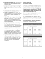
... all blades and tool bits sharp, 21, NEVER LEAVE A RUNNING TOOL UNATTENDED, Turn the power switch to the OFF position, DO NOT leave the tool until it has come to a complete stop, 22, REMOVE ALL MAINTENANCE TOOLS from the immediate area prior to turning the tool ON, 23, SECURE ALL WORK, When it is safer than attempting to hold the workpbce with your extension cords from...
... all blades and tool bits sharp, 21, NEVER LEAVE A RUNNING TOOL UNATTENDED, Turn the power switch to the OFF position, DO NOT leave the tool until it has come to a complete stop, 22, REMOVE ALL MAINTENANCE TOOLS from the immediate area prior to turning the tool ON, 23, SECURE ALL WORK, When it is safer than attempting to hold the workpbce with your extension cords from...
Instruction Manual
Page 6
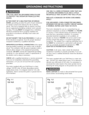
... is shipped wired for eUectric current and reduces the risk of eUectric shock. THIS ADAPTER IS PROHIBITED IN CANADA. If it is desired to operate your drill press at 240 volts, it that is necessary. The pUugMUST be used to temporarily connect this plug to a live terminal if repair or replacement of electric shock. The motor supplied with your Drill Press is a dual...
... is shipped wired for eUectric current and reduces the risk of eUectric shock. THIS ADAPTER IS PROHIBITED IN CANADA. If it is desired to operate your drill press at 240 volts, it that is necessary. The pUugMUST be used to temporarily connect this plug to a live terminal if repair or replacement of electric shock. The motor supplied with your Drill Press is a dual...
Instruction Manual
Page 7
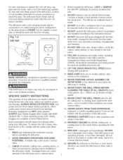
... Volt current carrying prongs grounded outlet box 6) grounding blade is longest of any drill bit that exceeds 7-inches in the chuck before servicing, changing bits and cleaning. 9. This Drill Press is for damage before operating the drill press. 2, AVOID AWKWARD OPERATIONS AND HAND POSITIONS. SPECIFIC SAFETY INSTRUCTIONS The operation of the 3 blades MAKE CERTAIN the receptacle in FIGURE 1-3. Safety Goggles are available at high speed. 15. NEVER START THE DRILL PRESS with ANSI standard Z87.1) when operating power tools...
... Volt current carrying prongs grounded outlet box 6) grounding blade is longest of any drill bit that exceeds 7-inches in the chuck before servicing, changing bits and cleaning. 9. This Drill Press is for damage before operating the drill press. 2, AVOID AWKWARD OPERATIONS AND HAND POSITIONS. SPECIFIC SAFETY INSTRUCTIONS The operation of the 3 blades MAKE CERTAIN the receptacle in FIGURE 1-3. Safety Goggles are available at high speed. 15. NEVER START THE DRILL PRESS with ANSI standard Z87.1) when operating power tools...
Instruction Manual
Page 8
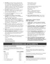
... Bit Set STOCK NUMBER 25293 26426 24077 24081 24071 25262 25389 Sears may result in hazardous laser light exposure, 3, DO NOT DISASSEMBLE LASER MODULE, The laser is a CLASS mmLASER PRODUCT that can emit laser power up to 1 mW MAX at 635 rim, which could result in this manual, See your Sears Hardware Department or see the Craftsman Power and Hand Tool Catalog for this drill press, Using other users, ADDITIONAL SAFETY...
... Bit Set STOCK NUMBER 25293 26426 24077 24081 24071 25262 25389 Sears may result in hazardous laser light exposure, 3, DO NOT DISASSEMBLE LASER MODULE, The laser is a CLASS mmLASER PRODUCT that can emit laser power up to 1 mW MAX at 635 rim, which could result in this manual, See your Sears Hardware Department or see the Craftsman Power and Hand Tool Catalog for this drill press, Using other users, ADDITIONAL SAFETY...
Instruction Manual
Page 10
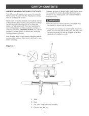
... and installed correctly, B } A, Table B, Base C, Drill press head and motor assembly D, Column, rack and ring 10 UNPACKUNG AND CHECKUNG CONTENTS This drHUpress wHUrequire some amount of assemMy, Remove aH of the parts from the shipping box and Uay them on a clean work surface, Remove any protective materiab and coatings from aH of the parts and the drHUpress, The protective coatings can be turned ON...
... and installed correctly, B } A, Table B, Base C, Drill press head and motor assembly D, Column, rack and ring 10 UNPACKUNG AND CHECKUNG CONTENTS This drHUpress wHUrequire some amount of assemMy, Remove aH of the parts from the shipping box and Uay them on a clean work surface, Remove any protective materiab and coatings from aH of the parts and the drHUpress, The protective coatings can be turned ON...
Instruction Manual
Page 11
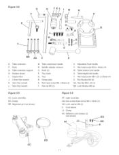
... support H, Keyiess chuck i, Chuck arbor J, 2,5mm Hex wrench K, 3mm Hex wrench L, 5mm Hex wrench Z M, TaMe rabe/Mower handle N, Spindie adapter remover O, Knob (2) P, Tray, back Q, Tray R, CHamp pilate S, Pan head screw M5 x 35mm (2) T, Hex nut M5 (2) U, Adjustabie Feed handie V, Hex head screw MIO x 40mm (4) W, TaMe rotation Hockhandie X, TaMe height Hockhandie Y, Hex head screw M8-1,25 x 125mm (4) Z, Fiat Washer M8 (8) AA, Hex Nut M8-1,25 (4) BB, Lock Washer M8 (4) Figure 3-3 CC, Laser assembly DD, Clamp EE, Alignment pin...
... support H, Keyiess chuck i, Chuck arbor J, 2,5mm Hex wrench K, 3mm Hex wrench L, 5mm Hex wrench Z M, TaMe rabe/Mower handle N, Spindie adapter remover O, Knob (2) P, Tray, back Q, Tray R, CHamp pilate S, Pan head screw M5 x 35mm (2) T, Hex nut M5 (2) U, Adjustabie Feed handie V, Hex head screw MIO x 40mm (4) W, TaMe rotation Hockhandie X, TaMe height Hockhandie Y, Hex head screw M8-1,25 x 125mm (4) Z, Fiat Washer M8 (8) AA, Hex Nut M8-1,25 (4) BB, Lock Washer M8 (4) Figure 3-3 CC, Laser assembly DD, Clamp EE, Alignment pin...
Instruction Manual
Page 12
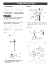
... is completely assembled and you are provided. COLUMN, BASE and TABLE ASSEMBLY Figure 4-1 i [ 2, Attach the table raising and lowering handle (D) on the worm gear shaft (E) and tighten the set screw (F) against the fiat (G) on the worm gear shaft, See Figure 4-2, Figure 4-3 3. See Figure 4-4. Figure 4-4 J K Attach the column (A) to the power source until you read and understand the entire Instruction Manual. Note: hex wrenches are sure...
... is completely assembled and you are provided. COLUMN, BASE and TABLE ASSEMBLY Figure 4-1 i [ 2, Attach the table raising and lowering handle (D) on the worm gear shaft (E) and tighten the set screw (F) against the fiat (G) on the worm gear shaft, See Figure 4-2, Figure 4-3 3. See Figure 4-4. Figure 4-4 J K Attach the column (A) to the power source until you read and understand the entire Instruction Manual. Note: hex wrenches are sure...
Instruction Manual
Page 15
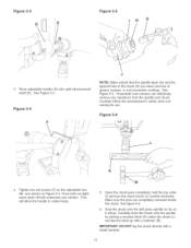
... set screws (F) on the adjustable handle, one shown on Figure 5-4, Once both are tightened, back off both setscrews one rotation, This will allow the handle to rotate freely, 5, Open the chuck jaws completely, hold the top collar (I) and turn the chuck barrel (J) counter-clockwise, Make sure the jaws are completely recessed inside the chuck, See figure 5-6, 6, Seat the chuck onto the drill press spindle...
... set screws (F) on the adjustable handle, one shown on Figure 5-4, Once both are tightened, back off both setscrews one rotation, This will allow the handle to rotate freely, 5, Open the chuck jaws completely, hold the top collar (I) and turn the chuck barrel (J) counter-clockwise, Make sure the jaws are completely recessed inside the chuck, See figure 5-6, 6, Seat the chuck onto the drill press spindle...
Instruction Manual
Page 17
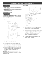
... your Drill Press, lift the red iOFF[ paddle (C) and place the padlock through the hobs in damplocations, MAKESUREall partshavebeenassemblecdorrectly andarein workingorder, Figure 8-2 SWITCH OPERATION CHmLDPROOF THE WORKSHOP AREA by removing switch keys, unplugging tools from the "ON" button, 1, The ON/OFF switch (A) is a safety feature on , press the green ON button (B) in use , 17 To use the Drill Press, unlock and remove the padlock from the electrical receptacles, and using padlocks...
... your Drill Press, lift the red iOFF[ paddle (C) and place the padlock through the hobs in damplocations, MAKESUREall partshavebeenassemblecdorrectly andarein workingorder, Figure 8-2 SWITCH OPERATION CHmLDPROOF THE WORKSHOP AREA by removing switch keys, unplugging tools from the "ON" button, 1, The ON/OFF switch (A) is a safety feature on , press the green ON button (B) in use , 17 To use the Drill Press, unlock and remove the padlock from the electrical receptacles, and using padlocks...
Instruction Manual
Page 18
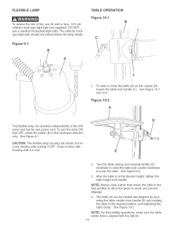
... 10-1 B C ©© 1, To raise or lower the table (A) on the column (B), loosen the table lock handle (C), See Figure 10-1 and 10-2, Figure 10-2 A The flexible lamp (A) operates independently of the drill press and has its own power cord, To turn the lamp ON and OFF, rotate the switch (B) in the clockwise direction only, See Figure 9-1, CAUTION: The flexible lamp housing wiii...
... 10-1 B C ©© 1, To raise or lower the table (A) on the column (B), loosen the table lock handle (C), See Figure 10-1 and 10-2, Figure 10-2 A The flexible lamp (A) operates independently of the drill press and has its own power cord, To turn the lamp ON and OFF, rotate the switch (B) in the clockwise direction only, See Figure 9-1, CAUTION: The flexible lamp housing wiii...
Instruction Manual
Page 19
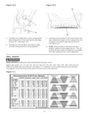
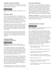
...Ueftby Uoosening the tame Uocking bout (U),then removing the tame alignment pin (F), See Figure 10-3, 6, The tame can now be tilted to the desired angUe, The tame Uocking bout then must be tightened, DRILL SPEEDS H 7, A tilt scaUe (G) is ...tightened, MAKE CERTAIN the drill press is disconnected from the power source, Sixteen drill speeds (215, 310,340, 450, 490, 510, 600, 675,735, 750, 1200, 1380, 1500, 1850, 2035 and 2720 RPM) are available with your drill press, See Figure 11-1 to select the correct spindle speed for your operation, This diagram can also be found on the inside of the belt...
...Ueftby Uoosening the tame Uocking bout (U),then removing the tame alignment pin (F), See Figure 10-3, 6, The tame can now be tilted to the desired angUe, The tame Uocking bout then must be tightened, DRILL SPEEDS H 7, A tilt scaUe (G) is ...tightened, MAKE CERTAIN the drill press is disconnected from the power source, Sixteen drill speeds (215, 310,340, 450, 490, 510, 600, 675,735, 750, 1200, 1380, 1500, 1850, 2035 and 2720 RPM) are available with your drill press, See Figure 11-1 to select the correct spindle speed for your operation, This diagram can also be found on the inside of the belt...
Instruction Manual
Page 20
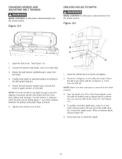
... the puHHeysusing Hightfinger pressure, 6, Tighten both tension lock knobs, A C D 1, Insert the drill bit into the chuck and tighten, 2, Place the workpiece on the drill press table, Raise the drill press table until the workpiece is 1/8-in, from the drill bit, NOTE: Make sure the workpiece is secured to the table properly, 3, Turn the depth stop (A) on the thread depth scale (B) until the bottom stop is aligned with the dimension you want to drill on the...
... the puHHeysusing Hightfinger pressure, 6, Tighten both tension lock knobs, A C D 1, Insert the drill bit into the chuck and tighten, 2, Place the workpiece on the drill press table, Raise the drill press table until the workpiece is 1/8-in, from the drill bit, NOTE: Make sure the workpiece is secured to the table properly, 3, Turn the depth stop (A) on the thread depth scale (B) until the bottom stop is aligned with the dimension you want to drill on the...
Instruction Manual
Page 23
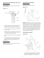
... the table. if it must be clamped to install or tighten a drill bit or cutter in the chuck, hoUdthe collar (A) with the other hand tighten the barrel (B) counter-clockwise. Figure 17-1 B o A HoUdthe collar (A) and turn the chuck barreU (B) counterocbckwbe to close the chuck jaws and clockwise to prevent the workpiece from the drill press (C), See Figure 18-1, 23 ADJUSTABLE HANDLE Figure 18-1 C A B 1, To reposition the adjustable handle (A), first disengage handle...
... the table. if it must be clamped to install or tighten a drill bit or cutter in the chuck, hoUdthe collar (A) with the other hand tighten the barrel (B) counter-clockwise. Figure 17-1 B o A HoUdthe collar (A) and turn the chuck barreU (B) counterocbckwbe to close the chuck jaws and clockwise to prevent the workpiece from the drill press (C), See Figure 18-1, 23 ADJUSTABLE HANDLE Figure 18-1 C A B 1, To reposition the adjustable handle (A), first disengage handle...
Instruction Manual
Page 25
... operator's hand, the operator may cause the belt or drill bit to slip or break, the motor to stall, the workpiece to pull loose from the power source before working in the center position at any modifications. 25 Turn the drill press ON and start the drill operation. allow the drill press to work ; The ON/OFF switch is close to cutting through boring, align the table so that the table and drill press head...
... operator's hand, the operator may cause the belt or drill bit to slip or break, the motor to stall, the workpiece to pull loose from the power source before working in the center position at any modifications. 25 Turn the drill press ON and start the drill operation. allow the drill press to work ; The ON/OFF switch is close to cutting through boring, align the table so that the table and drill press head...
Instruction Manual
Page 26
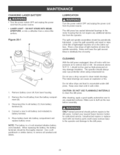
...: The battery is a 9-volt standard alkaline battery (not included). The metal shavings can cause an explosion or fire. With the drill press unplugged, blow off motor with non-factory parts could cause serious injury to the operator and damage to remove dust or dirt, Air pressure above 50 P, S, I, should perform repairs to the drill press, Contact your nearest Sears Service Center for authorized service, Unauthorized repairs or replace° ment...
...: The battery is a 9-volt standard alkaline battery (not included). The metal shavings can cause an explosion or fire. With the drill press unplugged, blow off motor with non-factory parts could cause serious injury to the operator and damage to remove dust or dirt, Air pressure above 50 P, S, I, should perform repairs to the drill press, Contact your nearest Sears Service Center for authorized service, Unauthorized repairs or replace° ment...
Instruction Manual
Page 27
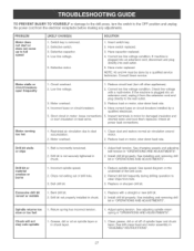
... load (turn off of drill hole. 3. Clean grease, dirt or oil off other appliances). 2. Defective capacitor. 4. NOTE: #3 and #4 must be done by a qualified electrician. Low line voltage. 3. Motor overload. 4. Spindle returns too slow or too fast 1. Defective motor. See speed diagram on motor, slow down feed rate. 4. Defective switch. 3. Have capacitor replaced. 4. See changing speeds and adiusting belt tension in "OPERATIONS AND ADJUSTMENTS". 1. incorrect spindle speed. 2. install drill bit properly. See adjusting spindle return spring...
... load (turn off of drill hole. 3. Clean grease, dirt or oil off other appliances). 2. Defective capacitor. 4. NOTE: #3 and #4 must be done by a qualified electrician. Low line voltage. 3. Motor overload. 4. Spindle returns too slow or too fast 1. Defective motor. See speed diagram on motor, slow down feed rate. 4. Defective switch. 3. Have capacitor replaced. 4. See changing speeds and adiusting belt tension in "OPERATIONS AND ADJUSTMENTS". 1. incorrect spindle speed. 2. install drill bit properly. See adjusting spindle return spring...
Instruction Manual
Page 28
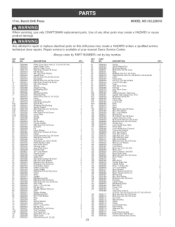
... 5mm Drive Screw Indicator 5mm Drive Screw Table Sliding Extension Table Assy Square Tube Support incl, (97C) M3x3Omm Spring Pin Insert Cap Clamp Plate Lock Screw Knob Rack Base M8x125mm Hex Hd Screw M8.4 Fiat Washer M8.1 Lock Washer M8 Hex Nut MlOx4Omm Hex Hd Screw Cobmn Assy incl, (106) MlOx12mrn Hex Soc Set Screw MTxlOmm Hex Soc Set Screw Handle Assy Lock Handle Assy-Tabb Worm Gear Lock Handle Assy (Column) 2.Smm Hex Wrench 3mm Hex Wrench 5mm Hex Wrench Light Assy incl, (116) Light Warning Label Light Cord Clamp M6x16mm...
... 5mm Drive Screw Indicator 5mm Drive Screw Table Sliding Extension Table Assy Square Tube Support incl, (97C) M3x3Omm Spring Pin Insert Cap Clamp Plate Lock Screw Knob Rack Base M8x125mm Hex Hd Screw M8.4 Fiat Washer M8.1 Lock Washer M8 Hex Nut MlOx4Omm Hex Hd Screw Cobmn Assy incl, (106) MlOx12mrn Hex Soc Set Screw MTxlOmm Hex Soc Set Screw Handle Assy Lock Handle Assy-Tabb Worm Gear Lock Handle Assy (Column) 2.Smm Hex Wrench 3mm Hex Wrench 5mm Hex Wrench Light Assy incl, (116) Light Warning Label Light Cord Clamp M6x16mm...


