Operation Manual
Page 1
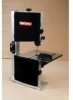
Sears, Roebuck and Co., Hoffman www.sears.comlcraftsman 25126,03 Draft (01/18/08) Estates, IL 60179 U.S.A. perator's nual ® tP BENCH TOP BAND SAW Model No. 351.214190 CAUTION: Read and follow all Safety Rules and Operating instructions before First Use of this Product.
Sears, Roebuck and Co., Hoffman www.sears.comlcraftsman 25126,03 Draft (01/18/08) Estates, IL 60179 U.S.A. perator's nual ® tP BENCH TOP BAND SAW Model No. 351.214190 CAUTION: Read and follow all Safety Rules and Operating instructions before First Use of this Product.
Operation Manual
Page 2
... changing blade. © Sears, Roebuck and Co. 2 Keep children out of this type of purchase, call 1-800-4-MY-HOME® TO ARRANGE FOR FREE REPAIR (or replacement if repair proves impossible). Use padlocks, master switches or remove switch keys to state. Form habit of power tools. Wear face mask or dust mask if operation is ever used for job. Do not use power tools in working order. Do not expose power tools to order replacement parts...
... changing blade. © Sears, Roebuck and Co. 2 Keep children out of this type of purchase, call 1-800-4-MY-HOME® TO ARRANGE FOR FREE REPAIR (or replacement if repair proves impossible). Use padlocks, master switches or remove switch keys to state. Form habit of power tools. Wear face mask or dust mask if operation is ever used for job. Do not use power tools in working order. Do not expose power tools to order replacement parts...
Operation Manual
Page 3
... to order replacement parts. Use operator's manual to avoid possible fire hazard. Learn the tool's operation, application and specific limitations. • Use recommended accessories (refer to dealer. Always wear safety goggles complying with carrier. Remove knob assembly (Key Nos. 16, 17 and 18) from saw frame. • Position table assembly on package) before assembling: A Miter Gauge Assembly B Table Assembly C Locking Handle with a light coating of the saw to a complete stop (Key Nos. 12 and 13) if necessary. • Set pointer at...
... to order replacement parts. Use operator's manual to avoid possible fire hazard. Learn the tool's operation, application and specific limitations. • Use recommended accessories (refer to dealer. Always wear safety goggles complying with carrier. Remove knob assembly (Key Nos. 16, 17 and 18) from saw frame. • Position table assembly on package) before assembling: A Miter Gauge Assembly B Table Assembly C Locking Handle with a light coating of the saw to a complete stop (Key Nos. 12 and 13) if necessary. • Set pointer at...
Operation Manual
Page 4
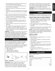
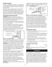
... CORDS • The use . Up to touch the terminals of any manner. The Craftsman 9" Bench Top Band Saw features welded steel frame construction and a solid cast iron table surface to prevent unauthorized use of plug when installing or removing from electrical shock. Saw also features a blade tracking window and dust collection port. 4 Normal loads will cause some drop in voltage and loss of power. ® Wires...
... CORDS • The use . Up to touch the terminals of any manner. The Craftsman 9" Bench Top Band Saw features welded steel frame construction and a solid cast iron table surface to prevent unauthorized use of plug when installing or removing from electrical shock. Saw also features a blade tracking window and dust collection port. 4 Normal loads will cause some drop in voltage and loss of power. ® Wires...
Operation Manual
Page 5
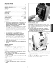
... protection. + Do not remove jammed cutoff pieces until blade has stopped. The switch cannot be locked from power source. + Pull the key out. Locking Switch in OFF Position REMOVING BLADE WARNING: Disconnect band saw blades. Avoid under tensioning to eliminate back and forth, side to side blade movement as it cuts. + Use proper blade for the cutting operation. + After turning saw can be turned off but cannot be turned on again. + To replace key, slide key into the slot...
... protection. + Do not remove jammed cutoff pieces until blade has stopped. The switch cannot be locked from power source. + Pull the key out. Locking Switch in OFF Position REMOVING BLADE WARNING: Disconnect band saw blades. Avoid under tensioning to eliminate back and forth, side to side blade movement as it cuts. + Use proper blade for the cutting operation. + After turning saw can be turned off but cannot be turned on again. + To replace key, slide key into the slot...
Operation Manual
Page 6
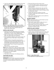
... 5). WARNING: Be very careful; Do not perform tracking adjustment while band saw is necessary for rear support. View blade through tracking window. If blade rides away from wheels causing serious injury. If blade rides toward cabinet, turn knob clockwise. Adjust guides as described in between blade guards. • Tension blade by hand in following sections. Use a feeler gauge to Figures 5 and 11. Guide Pin Bearing Figure 7 = Upper Blade Guides Lock adjustment by tightening nut (Key No. 13).
... 5). WARNING: Be very careful; Do not perform tracking adjustment while band saw is necessary for rear support. View blade through tracking window. If blade rides away from wheels causing serious injury. If blade rides toward cabinet, turn knob clockwise. Adjust guides as described in between blade guards. • Tension blade by hand in following sections. Use a feeler gauge to Figures 5 and 11. Guide Pin Bearing Figure 7 = Upper Blade Guides Lock adjustment by tightening nut (Key No. 13).
Operation Manual
Page 7
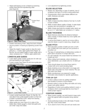
... cut . A 1A"wide blade can be cut. Adjust the height of upper guide until it clears workpiece by tightening socket head bolt. BLADE THICKNESS • Blade thickness describes the distance between 6 to 8 teeth per inch or tooth size. CONTOUR SAWING When contour sawing, use hands over 7 Avoid positioning hands in contact with work. ® For soft materials, the proper blade has between sides of the saw table and using proper work guiding method...
... cut . A 1A"wide blade can be cut. Adjust the height of upper guide until it clears workpiece by tightening socket head bolt. BLADE THICKNESS • Blade thickness describes the distance between 6 to 8 teeth per inch or tooth size. CONTOUR SAWING When contour sawing, use hands over 7 Avoid positioning hands in contact with work. ® For soft materials, the proper blade has between sides of the saw table and using proper work guiding method...
Operation Manual
Page 8
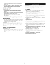
.... KEEP BAND SAW IN REPAIR • If power cord is disconnected from drive wheel. Cut small corners by loosening locking handle located on wheels will cause poor tracking and blade slippage. • Keep mechanisms and threaded or sliding surfaces clean and free of paste wax to table top to produce angled cuts. BEVEL CUTTING Refer to Figure 10. • Perform bevel cutting by tilting table to order parts. 8 WARNING: Make certain that brush (Key No...
.... KEEP BAND SAW IN REPAIR • If power cord is disconnected from drive wheel. Cut small corners by loosening locking handle located on wheels will cause poor tracking and blade slippage. • Keep mechanisms and threaded or sliding surfaces clean and free of paste wax to table top to produce angled cuts. BEVEL CUTTING Refer to Figure 10. • Perform bevel cutting by tilting table to order parts. 8 WARNING: Make certain that brush (Key No...
Operation Manual
Page 9
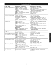
... blade back 1. Replace blade 6. Blade guide brackets loose Teeth ripping from blade 1. Teeth filling with coarser teeth 3. Blade too coarse 2. Work not square 2. Dull blade 6. Use miter gauge; Rate of feed too great 3. Adjust blade guides; Decrease feed rate 3. Use blade with material Motor running too hot 1. Teeth in or on table 2. adjust tilt of blade 1. Adjust upper guide to just clear workpiece byW' 5. Replace with work (typical when cutting pipe) 2. Excessive dirt and chips Saw will not start Loose electrical...
... blade back 1. Replace blade 6. Blade guide brackets loose Teeth ripping from blade 1. Teeth filling with coarser teeth 3. Blade too coarse 2. Work not square 2. Dull blade 6. Use miter gauge; Rate of feed too great 3. Adjust blade guides; Decrease feed rate 3. Use blade with material Motor running too hot 1. Teeth in or on table 2. adjust tilt of blade 1. Adjust upper guide to just clear workpiece byW' 5. Replace with work (typical when cutting pipe) 2. Excessive dirt and chips Saw will not start Loose electrical...
Operation Manual
Page 11
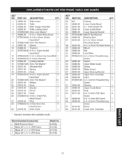
... Socket 2 Pan Head Screw 4-0.7 x 6mm Flat Head Screw 4 Mount 1 Nut 1 Limit Plate 1 4.2 x 15mm Threadforming 1 Screw* Guard 1 Upper Blade Guide 1 Spring 1 Blade Guard 1 Upper Bearing Bracket 1 Upper Door Assembly 1 Latch 2 4.2 x 9.5mm Threadforming 1 Screw* Window 1 Upper Guide Block 1 Seal 1 4-0.7 x 8mm Flat Head 8 Screw 4-0.7 x 5mm Set Screw 1 4.8 x 9.5mm Threadforming 1 Screw Brush 1 Lower Door Assembly 1 11 Table Insert 1 Table 1 Miter Gauge Assembly 1 Table Locking Insert 1 6mm Lock Washer* 1 6-1.0 x 12mm Wing Screw 1 8-1.25 x 20mm...
... Socket 2 Pan Head Screw 4-0.7 x 6mm Flat Head Screw 4 Mount 1 Nut 1 Limit Plate 1 4.2 x 15mm Threadforming 1 Screw* Guard 1 Upper Blade Guide 1 Spring 1 Blade Guard 1 Upper Bearing Bracket 1 Upper Door Assembly 1 Latch 2 4.2 x 9.5mm Threadforming 1 Screw* Window 1 Upper Guide Block 1 Seal 1 4-0.7 x 8mm Flat Head 8 Screw 4-0.7 x 5mm Set Screw 1 4.8 x 9.5mm Threadforming 1 Screw Brush 1 Lower Door Assembly 1 11 Table Insert 1 Table 1 Miter Gauge Assembly 1 Table Locking Insert 1 6mm Lock Washer* 1 6-1.0 x 12mm Wing Screw 1 8-1.25 x 20mm...
Operation Manual
Page 13
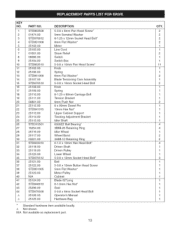
... Pan Head Screw* Knob Spring 6mm Flat Washer* Blade Tensioning Cam Assembly 5-0.8 x lOmm Socket Head Bolt Knob Spring 8-1.25 x 80mm Carriage Bolt Tension Bracket 8mm Push Nut 8 x 90mm Dowel Pin lOmm Hex Nut* Upper Cabinet Support Tracking Adjustment Bracket Idler Shaft 6000ZZ Ball Bearing* 3BMI-26 Retaining Ring Idler Wheel Wheel Band 3AMI-IO Retaining Ring 6-1.0 x lOmm Hex Head Bolt* Driven Shaft Driven Pulley Lower Wheel 5-0.8 x 12mm Socket Head Bolt* Belt 5-0.8 x lOmm Button Head Screw...
... Pan Head Screw* Knob Spring 6mm Flat Washer* Blade Tensioning Cam Assembly 5-0.8 x lOmm Socket Head Bolt Knob Spring 8-1.25 x 80mm Carriage Bolt Tension Bracket 8mm Push Nut 8 x 90mm Dowel Pin lOmm Hex Nut* Upper Cabinet Support Tracking Adjustment Bracket Idler Shaft 6000ZZ Ball Bearing* 3BMI-26 Retaining Ring Idler Wheel Wheel Band 3AMI-IO Retaining Ring 6-1.0 x lOmm Hex Head Bolt* Driven Shaft Driven Pulley Lower Wheel 5-0.8 x 12mm Socket Head Bolt* Belt 5-0.8 x lOmm Button Head Screw...

Operation Manual
Page 24
...-6655 (U.S.A.) 1-800-361-6665 (Canada) Para pedir servicio de reparaci6n a domicilio, y para ordenar piezas: 1-888-SU-HOGAR ® (1-888-784-6427) Au Canada pour service en fran(_ais: 1-800-LE-FOYER Mc (1-800-533-6937) www. se a rs. For the replacement parts, accessories and owner's manuals that you need to do-it ! of Sears Brands, LLC ® Marca Registrada / rM...
...-6655 (U.S.A.) 1-800-361-6665 (Canada) Para pedir servicio de reparaci6n a domicilio, y para ordenar piezas: 1-888-SU-HOGAR ® (1-888-784-6427) Au Canada pour service en fran(_ais: 1-800-LE-FOYER Mc (1-800-533-6937) www. se a rs. For the replacement parts, accessories and owner's manuals that you need to do-it ! of Sears Brands, LLC ® Marca Registrada / rM...


