
Hardware Maintenance Manual
Page 3
... not been installed, operated, repaired, or maintained in Technical Data and Computer Software clause at FAR §52.227-19 and subparagraph (c)(1)(ii) of Cisco. MODIFY THE SOFTWARE; Cisco warrants that the Software will substantially conform to the published specifications for such Software, if used in such a way that supplied the Product to Customer or to operate its Sales or Service Partner in...
... not been installed, operated, repaired, or maintained in Technical Data and Computer Software clause at FAR §52.227-19 and subparagraph (c)(1)(ii) of Cisco. MODIFY THE SOFTWARE; Cisco warrants that the Software will substantially conform to the published specifications for such Software, if used in such a way that supplied the Product to Customer or to operate its Sales or Service Partner in...

Hardware Maintenance Manual
Page 6
...Token Ring Connections 3-2 Making Ethernet Connections 3-3 Making Serial Connections 3-4 Making BRI Connections 3-6 Making FDDI Network Connections 3-11 Making T1 Connections 3-14 Making E1 Connections 3-16 Making ATM Connections 3-17 Connecting Routers with a DC-Input Power Supply 3-19 Wiring the DC-Input Power Supply 3-20 Making Final Connections to the Router 3-22 Chapter 4 Troubleshooting the Initial Hardware Configuration 4-1 Problem Solving 4-1 Troubleshooting the Power and Cooling Systems 4-2 Troubleshooting the Network Processor Modules and Cables 4-2 Environmental Reporting Features...
...Token Ring Connections 3-2 Making Ethernet Connections 3-3 Making Serial Connections 3-4 Making BRI Connections 3-6 Making FDDI Network Connections 3-11 Making T1 Connections 3-14 Making E1 Connections 3-16 Making ATM Connections 3-17 Connecting Routers with a DC-Input Power Supply 3-19 Wiring the DC-Input Power Supply 3-20 Making Final Connections to the Router 3-22 Chapter 4 Troubleshooting the Initial Hardware Configuration 4-1 Problem Solving 4-1 Troubleshooting the Power and Cooling Systems 4-2 Troubleshooting the Network Processor Modules and Cables 4-2 Environmental Reporting Features...

Hardware Maintenance Manual
Page 15
... software configuration information, refer to install and maintain the Cisco 4000-M, Cisco 4500-M, and the Cisco 4700. UniverCD is updated and shipped monthly, so it may be familiar with a DC-input power supply. Document Organization The major sections of the Cisco 4000 series features and physical specifications. • Chapter 2, "Preparing for Installation," includes safety recommendations, tools and equipment, site requirements, an installation checklist, console and auxiliary port cable connection considerations, network connection...
... software configuration information, refer to install and maintain the Cisco 4000-M, Cisco 4500-M, and the Cisco 4700. UniverCD is updated and shipped monthly, so it may be familiar with a DC-input power supply. Document Organization The major sections of the Cisco 4000 series features and physical specifications. • Chapter 2, "Preparing for Installation," includes safety recommendations, tools and equipment, site requirements, an installation checklist, console and auxiliary port cable connection considerations, network connection...

Hardware Maintenance Manual
Page 20
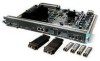
... router platform • Flash memory capability • User-upgradable network processor modules, shared memory, and processor local memory • Hardware thermal alarm to three network processor modules at a time, including Ethernet, Token Ring, serial, single-mode and multimode Fiber Distributed Data Interface (FDDI), ISDN BRI, G.703, channelized T1/PRI, channelized T1/PRI, and ATM modules. Series Specifications Figure 1-1 shows the front panel of the single and dual Token Ring, dual Ethernet, and FDDI modules. 1-2 Cisco 4000 Series Hardware Installation...
... router platform • Flash memory capability • User-upgradable network processor modules, shared memory, and processor local memory • Hardware thermal alarm to three network processor modules at a time, including Ethernet, Token Ring, serial, single-mode and multimode Fiber Distributed Data Interface (FDDI), ISDN BRI, G.703, channelized T1/PRI, channelized T1/PRI, and ATM modules. Series Specifications Figure 1-1 shows the front panel of the single and dual Token Ring, dual Ethernet, and FDDI modules. 1-2 Cisco 4000 Series Hardware Installation...

Hardware Maintenance Manual
Page 28
... serial port to an external network. • To connect a serial port to a T1 network, you might include the following : - Removal or replacement of ongoing router maintenance and expansion history. Maintenance procedures performed - Use the Installation Checklist to verify steps in the installation and maintenance of all actions relevant to it. Site Log entries might need a T1 channel service unit/data service unit (CSU/DSU) that converts the High-Level Data Link Control...
... serial port to an external network. • To connect a serial port to a T1 network, you might include the following : - Removal or replacement of ongoing router maintenance and expansion history. Maintenance procedures performed - Use the Installation Checklist to verify steps in the installation and maintenance of all actions relevant to it. Site Log entries might need a T1 channel service unit/data service unit (CSU/DSU) that converts the High-Level Data Link Control...

Hardware Maintenance Manual
Page 37
...pin D-shell connector known as EIA/TIA-232. Table 2-4 lists the IEEE-recommended maximum speeds and distances for V.35, X.21, and EIA-530. The network end of the adapter cable is commonly used. Serial Line Distance Limitations Serial signals can support 4-Mbps rates. EIA/TIA-232 Connections EIA/TIA-232, the most common interface standard in the United States, supports unbalanced circuits at your router...speeds and distances greater than those listed. however, the serial module ports support synchronous connections, and the console and auxiliary ports support asynchronous connections...
...pin D-shell connector known as EIA/TIA-232. Table 2-4 lists the IEEE-recommended maximum speeds and distances for V.35, X.21, and EIA-530. The network end of the adapter cable is commonly used. Serial Line Distance Limitations Serial signals can support 4-Mbps rates. EIA/TIA-232 Connections EIA/TIA-232, the most common interface standard in the United States, supports unbalanced circuits at your router...speeds and distances greater than those listed. however, the serial module ports support synchronous connections, and the console and auxiliary ports support asynchronous connections...

Hardware Maintenance Manual
Page 43
... entered in the configuration file, then dte-invert-timing must be configured for the module to a modem, CSU/DSU, or other device as DCE must be manually changed. and EIA-530 DTE. An error message will be configured with the system. This cable, available from your customer service representative, is normally ordered with the clockrate command. Figure 2-23 Router Serial Cable Connections Serial port 50-pin connector Serial transition cable Chassis H1037a EIA...
... entered in the configuration file, then dte-invert-timing must be configured for the module to a modem, CSU/DSU, or other device as DCE must be manually changed. and EIA-530 DTE. An error message will be configured with the system. This cable, available from your customer service representative, is normally ordered with the clockrate command. Figure 2-23 Router Serial Cable Connections Serial port 50-pin connector Serial transition cable Chassis H1037a EIA...
Hardware Maintenance Manual
Page 44
... use a port in DCE mode, you must connect a DCE interface cable and set the clock rate on the Four-Port Serial Module Systems that follows, the serial 0 port is defined as 72 Kbps: interface serial 1 clockrate 72000 Use the no clockrate command to accept the internal clock signal: interface serial 0 dce-terminal-timing-enable 2-22 Cisco 4000 Series Hardware Installation and Maintenance The default operation on a dual serial module is configured to remove the clock rate for the DCE device...
... use a port in DCE mode, you must connect a DCE interface cable and set the clock rate on the Four-Port Serial Module Systems that follows, the serial 0 port is defined as 72 Kbps: interface serial 1 clockrate 72000 Use the no clockrate command to accept the internal clock signal: interface serial 0 dce-terminal-timing-enable 2-22 Cisco 4000 Series Hardware Installation and Maintenance The default operation on a dual serial module is configured to remove the clock rate for the DCE device...

Hardware Maintenance Manual
Page 64
..., where the NT1 is customer owned. kHz = kilohertz. 2. The NT1 is an RJ-45 8-pin connector. Making Network Connections Caution For proper router operation, both ends of the BRI port (RJ-45 connector) even when power is turned OFF. (See Figure 3-7 and Figure 3-8.) The BRI network processor module supports point-to -multipoint configuration, D-channel access procedures are accessible in each direction at an S interface (CCITT specification I.430 section 3.1).
..., where the NT1 is customer owned. kHz = kilohertz. 2. The NT1 is an RJ-45 8-pin connector. Making Network Connections Caution For proper router operation, both ends of the BRI port (RJ-45 connector) even when power is turned OFF. (See Figure 3-7 and Figure 3-8.) The BRI network processor module supports point-to -multipoint configuration, D-channel access procedures are accessible in each direction at an S interface (CCITT specification I.430 section 3.1).

Hardware Maintenance Manual
Page 67
Installation Requirements (Special Considerations) Read the following subassemblies: • BRI network processor module mother card (part number 73-1219) • 1 or 2 BRI adapter interface cards (part number 73-1220) • BRI-ISDN (point-to-point use of the BRI network processor module. This is fully transportable between the ISDN ports used. The BRI network processor module is accommodated for by the use ) Software Version 1.0 The BRI network processor module provides users of compatible host routers or bridge chassis with other...
Installation Requirements (Special Considerations) Read the following subassemblies: • BRI network processor module mother card (part number 73-1219) • 1 or 2 BRI adapter interface cards (part number 73-1220) • BRI-ISDN (point-to-point use of the BRI network processor module. This is fully transportable between the ISDN ports used. The BRI network processor module is accommodated for by the use ) Software Version 1.0 The BRI network processor module provides users of compatible host routers or bridge chassis with other...

Hardware Maintenance Manual
Page 72
...(config-controller)# 3-14 Cisco 4000 Series Hardware Installation and Maintenance Press the Return key after each configuration step. Router(config)# Step 2 At the prompt, specify the controller to up in the existing configuration. Router(config-controller)# linecode b8zs Router(config-controller)# %CONTROLLER-3-UPDOWN: Controller T1 1, changed state to configure by entering the subcommand cont, followed by the Cisco 4000 series, use the privileged-level configure command to use bridging The following : • T1 information, for example clock source, line code, and framing type...
...(config-controller)# 3-14 Cisco 4000 Series Hardware Installation and Maintenance Press the Return key after each configuration step. Router(config)# Step 2 At the prompt, specify the controller to up in the existing configuration. Router(config-controller)# linecode b8zs Router(config-controller)# %CONTROLLER-3-UPDOWN: Controller T1 1, changed state to configure by entering the subcommand cont, followed by the Cisco 4000 series, use the privileged-level configure command to use bridging The following : • T1 information, for example clock source, line code, and framing type...

Hardware Maintenance Manual
Page 74
... framing type. Making Network Connections Making E1 Connections If you installed a new CE1 module or if you want to change the configuration of the configuration subcommands as follows: Router# conf t Enter configuration commands, one per line. Router(config-controller)# int serial 1:0 Step 6 At the prompt, assign an IP address and subnet mask to the interface with the ip address configuration subcommand as the following example: Router(config-if)# ip address 1.1.15.1 255.255.255.0 Router(config-if)# Step 7 Add any additional configuration subcommands required to enable routing protocols...
... framing type. Making Network Connections Making E1 Connections If you installed a new CE1 module or if you want to change the configuration of the configuration subcommands as follows: Router# conf t Enter configuration commands, one per line. Router(config-controller)# int serial 1:0 Step 6 At the prompt, assign an IP address and subnet mask to the interface with the ip address configuration subcommand as the following example: Router(config-if)# ip address 1.1.15.1 255.255.255.0 Router(config-if)# Step 7 Add any additional configuration subcommands required to enable routing protocols...
Hardware Maintenance Manual
Page 75
... is the default): Router(config-if)#atm sonet stm-1 Step 4 Assign protocol addresses to the interface: Router(config-if)# ip address 1.1.1.1 255.255.255.0 Installing the Router 3-17 Refer to configure by entering the subcommand int, followed by entering disable at the prompt as follows: Router# write memory The system will be the source of the configuration subcommands: Router# conf t Step 2 Specify the unit to the printed Router Products Configuration Guide and Router Products Command Reference...
... is the default): Router(config-if)#atm sonet stm-1 Step 4 Assign protocol addresses to the interface: Router(config-if)# ip address 1.1.1.1 255.255.255.0 Installing the Router 3-17 Refer to configure by entering the subcommand int, followed by entering disable at the prompt as follows: Router# write memory The system will be the source of the configuration subcommands: Router# conf t Step 2 Specify the unit to the printed Router Products Configuration Guide and Router Products Command Reference...
Hardware Maintenance Manual
Page 76
... be setup manually. Making Network Connections Step 5 Create the Permanent Virtual Circuits (PVCs). Step 1 At the priviledged-mode prompt, enter the configuration mode and specify that follows is for the ATM unit 0: Router(config)# int atm 0 Step 3 Specify the framing type (for SONET interfaces, STS-3c is a switch in order to PVCs. Router(config-if)# atm pvc 1 0 5 qsaal 3-18 Cisco 4000 Series Hardware Installation and Maintenance Step 6 Assign the appropriate map-list to the interface: Router(config-map-list...
... be setup manually. Making Network Connections Step 5 Create the Permanent Virtual Circuits (PVCs). Step 1 At the priviledged-mode prompt, enter the configuration mode and specify that follows is for the ATM unit 0: Router(config)# int atm 0 Step 3 Specify the framing type (for SONET interfaces, STS-3c is a switch in order to PVCs. Router(config-if)# atm pvc 1 0 5 qsaal 3-18 Cisco 4000 Series Hardware Installation and Maintenance Step 6 Assign the appropriate map-list to the interface: Router(config-map-list...
Hardware Maintenance Manual
Page 118
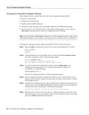
... IOS software, follow : • Recover a lost password. • Change the console baud rate. • Enable or disable the Break function. • Manually boot the operating system using the b command at next reload) Step 6 Reboot the router. B-2 Cisco 4000 Series Hardware Installation and Maintenance end with DELETE, CTRL/W, and CTRL/U; Edit with CTRL/Z Step 3 To set the contents of the virtual configuration register follow these steps: Step 1 Enter the enable command and your password to memory; Configuration register changes take...
... IOS software, follow : • Recover a lost password. • Change the console baud rate. • Enable or disable the Break function. • Manually boot the operating system using the b command at next reload) Step 6 Reboot the router. B-2 Cisco 4000 Series Hardware Installation and Maintenance end with DELETE, CTRL/W, and CTRL/U; Edit with CTRL/Z Step 3 To set the contents of the virtual configuration register follow these steps: Step 1 Enter the enable command and your password to memory; Configuration register changes take...
Hardware Maintenance Manual
Page 119
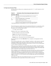
... netboot commands up . If you must have console port access to boot the first file in boot Flash memory without a file being successfully booted, the router will boot up to six times unless the boot default ROM software if netboot fails bit (bit 13 of the virtual configuration register) is reached. If the netboot attempt fails, the boot helper image in the configuration file, the router boots the system software as a system image 02-F Specifies a default netboot filename Enables default booting...
... netboot commands up . If you must have console port access to boot the first file in boot Flash memory without a file being successfully booted, the router will boot up to six times unless the boot default ROM software if netboot fails bit (bit 13 of the virtual configuration register) is reached. If the netboot attempt fails, the boot helper image in the configuration file, the router boots the system software as a system image 02-F Specifies a default netboot filename Enables default booting...
Hardware Maintenance Manual
Page 124
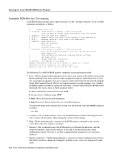
... reboots the system and boots the default software from TFTP server, but do not begin execution O Show software configuration register option settings P Set break point S Single step next instruction T function Test device (? Register names are among the most useful: • Boot-The b command with modifier M G [address] Begin execution H Help for help) Deposit and Examine sizes may be useful as a diagnostic reading if a problem occurs, such as defined by the boot field in Flash memory b flash...
... reboots the system and boots the default software from TFTP server, but do not begin execution O Show software configuration register option settings P Set break point S Single step next instruction T function Test device (? Register names are among the most useful: • Boot-The b command with modifier M G [address] Begin execution H Help for help) Deposit and Examine sizes may be useful as a diagnostic reading if a problem occurs, such as defined by the boot field in Flash memory b flash...
Hardware Maintenance Manual
Page 129
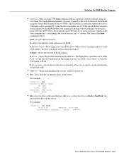
... named device, dir device, where the device is not recognized by the ROM monitor, the system will attempt to power-on. • dev-Lists boot device identifications on the router. The boot command with no arguments will boot from a network TFTP server. The local device (see the description of b device following) can be specified by name or IP address, the boot command will boot the first image in the flash bank. • reset or i-Resets...
... named device, dir device, where the device is not recognized by the ROM monitor, the system will attempt to power-on. • dev-Lists boot device identifications on the router. The boot command with no arguments will boot from a network TFTP server. The local device (see the description of b device following) can be specified by name or IP address, the boot command will boot the first image in the flash bank. • reset or i-Resets...
Hardware Maintenance Manual
Page 138
...3-22 configuration register B-1-B-6 boot field B-3 changing settings B-2 Cisco 4500-M D-4 Cisco 4700 D-4 displaying settings C-3 resetting C-3 confreg command D-4 connections 10BaseT 2-10 9-pin D-type 3-2 auxiliary port 2-9 considerations when making 2-10 console port 2-9 Ethernet attaching to network 3-3 port, considerations 2-12 final 3-22 NT1 3-6 optical bypass switch 3-13 power 3-22 preparing to make 2-7 serial 3-5 Token Ring 2-13, 3-2 console cable, pinout A-2 port alarm message 4-3 connections 2-9 console port RJ-45 connector caution 3-8, A-22 context command D-4 conventions serial modes...
...3-22 configuration register B-1-B-6 boot field B-3 changing settings B-2 Cisco 4500-M D-4 Cisco 4700 D-4 displaying settings C-3 resetting C-3 confreg command D-4 connections 10BaseT 2-10 9-pin D-type 3-2 auxiliary port 2-9 considerations when making 2-10 console port 2-9 Ethernet attaching to network 3-3 port, considerations 2-12 final 3-22 NT1 3-6 optical bypass switch 3-13 power 3-22 preparing to make 2-7 serial 3-5 Token Ring 2-13, 3-2 console cable, pinout A-2 port alarm message 4-3 connections 2-9 console port RJ-45 connector caution 3-8, A-22 context command D-4 conventions serial modes...

Hardware Maintenance Manual
Page 141
...port A-8 EIA-530 dual-port A-16 four-port A-18 EIA-TIA-232, four-port A-5 Ethernet (AUI) A-19 RJ-45 A-20 serial cable A-3-A-18 Token Ring A-21 V.35 dual-port A-10 four-port A-11 X.21 dual-port A-14 four-port A-15 polarity, Ethernet LED 4-5 port locations 2-7 software configuration, serial 4-8 power LED indication 3-22 light 4-3 specifications 1-3 supply features 2-4 system, troubleshooting 4-2 preparing for installation 2-1 to make connections 2-7 preventing ESD damage 2-3 preventive site configuration 2-4 printing summary of ROM monitor commands problem indications 4-3 temperature 4-3 problem...
...port A-8 EIA-530 dual-port A-16 four-port A-18 EIA-TIA-232, four-port A-5 Ethernet (AUI) A-19 RJ-45 A-20 serial cable A-3-A-18 Token Ring A-21 V.35 dual-port A-10 four-port A-11 X.21 dual-port A-14 four-port A-15 polarity, Ethernet LED 4-5 port locations 2-7 software configuration, serial 4-8 power LED indication 3-22 light 4-3 specifications 1-3 supply features 2-4 system, troubleshooting 4-2 preparing for installation 2-1 to make connections 2-7 preventing ESD damage 2-3 preventive site configuration 2-4 printing summary of ROM monitor commands problem indications 4-3 temperature 4-3 problem...


