
Installation Guide
Page 2
...-frequency energy and, if not installed and used in accordance with the limits for Class A or Class B digital devices. These specifications are designed to part 15 of its peripheral devices. However, there is operated in a residential installation. could void the FCC approval... to correct the interference at your equipment is not installed in accordance with Cisco's installation instructions, it was probably caused by FCC regulations, and you may cause interference with the specifications in which case users will not occur in accordance with radio and television...
...-frequency energy and, if not installed and used in accordance with the limits for Class A or Class B digital devices. These specifications are designed to part 15 of its peripheral devices. However, there is operated in a residential installation. could void the FCC approval... to correct the interference at your equipment is not installed in accordance with Cisco's installation instructions, it was probably caused by FCC regulations, and you may cause interference with the specifications in which case users will not occur in accordance with radio and television...

Installation Guide
Page 8
... B-1 1000BaseX Ports B-2 Gigastack Port B-3 Console Port B-3 Cable and Adapter Specifications B-4 Crossover and Straight-Through Cable Pinouts B-4 Rollover Cable and Adapter Pinouts B-5 Identifying a Rollover Cable B-5 Connecting to a PC B-6 Connecting to a Terminal B-7 Translated Safety Warnings C-1 Attaching the Cisco RPS (model PWR600-AC-RPS) C-2 Attaching the Cisco RPS (model PWR300-AC-RPS-N1) C-4 Service Personnel Warning...
... B-1 1000BaseX Ports B-2 Gigastack Port B-3 Console Port B-3 Cable and Adapter Specifications B-4 Crossover and Straight-Through Cable Pinouts B-4 Rollover Cable and Adapter Pinouts B-5 Identifying a Rollover Cable B-5 Connecting to a PC B-6 Connecting to a Terminal B-7 Translated Safety Warnings C-1 Attaching the Cisco RPS (model PWR600-AC-RPS) C-2 Attaching the Cisco RPS (model PWR300-AC-RPS-N1) C-4 Service Personnel Warning...

Installation Guide
Page 12
... overview of how the switch could be used to connect to set up the switch initial configuration. Appendix B, "Connector and Cable Specifications," describes the connectors, cables, and adapters that might arise when you are installing the switch. Examples of the switch. It describes...enter is in boldface screen font. • Nonprinting characters, such as passwords or tabs, are in italic. Catalyst 3500 Series XL Hardware Installation Guide xii 78-6456-04 Organization Preface Organization This guide is organized into the following conventions to convey instructions and ...
... overview of how the switch could be used to connect to set up the switch initial configuration. Appendix B, "Connector and Cable Specifications," describes the connectors, cables, and adapters that might arise when you are installing the switch. Examples of the switch. It describes...enter is in boldface screen font. • Nonprinting characters, such as passwords or tabs, are in italic. Catalyst 3500 Series XL Hardware Installation Guide xii 78-6456-04 Organization Preface Organization This guide is organized into the following conventions to convey instructions and ...

Installation Guide
Page 25
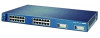
... Table 1-2 list their features. 78-6456-04 Catalyst 3500 Series XL Hardware Installation Guide 1-1 A feature specific to the Catalyst 3524-PWR XL switch is its ability to provide inline power to Cisco IP Phones. (Phone adapters are stackable 10/100 Ethernet switches to the Catalyst 3524-PWR XL 10/100 switch ports.) Figure 1-1 shows the switch models...
... Table 1-2 list their features. 78-6456-04 Catalyst 3500 Series XL Hardware Installation Guide 1-1 A feature specific to the Catalyst 3524-PWR XL switch is its ability to provide inline power to Cisco IP Phones. (Phone adapters are stackable 10/100 Ethernet switches to the Catalyst 3524-PWR XL 10/100 switch ports.) Figure 1-1 shows the switch models...

Installation Guide
Page 32
...10 Mbps can be connected to operate in Appendix B, "Connector and Cable Specifications." Refer to the following phones: Cisco IP Phone 7960, Cisco IP Phone 7940, and Cisco IP Phone 7910 • Automatically detect if a Cisco IP Phone is connected. When you can sense the speed and duplex ... for autonegotiation, the port can control whether or not a Catalyst 3524-PWR XL 10/100 port automatically provides power when a Cisco IP Phone is connected On a per -port priority override. However, the Catalyst 3524-PWR XL 10/100 ports can be sure that the cable is , the fastest...
...10 Mbps can be connected to operate in Appendix B, "Connector and Cable Specifications." Refer to the following phones: Cisco IP Phone 7960, Cisco IP Phone 7940, and Cisco IP Phone 7910 • Automatically detect if a Cisco IP Phone is connected. When you can sense the speed and duplex ... for autonegotiation, the port can control whether or not a Catalyst 3524-PWR XL 10/100 port automatically provides power when a Cisco IP Phone is connected On a per -port priority override. However, the Catalyst 3524-PWR XL 10/100 ports can be sure that the cable is , the fastest...

Installation Guide
Page 47
Cisco RPS Connector Specific Cisco RPS models support specific Catalyst 3500 XL switches: • Cisco RPS 600 (model PWR600-AC-RPS)-Supports the Catalyst 3512, 3524, 3548, and 3508 XL switches • Cisco RPS 300 (model PWR300-AC-RPS)-Supports the Catalyst 3524-PWR XL switch RPS Connector on the Cisco RPS 600, refer to the Cisco Redundant Power System Hardware Installation Guide...
Cisco RPS Connector Specific Cisco RPS models support specific Catalyst 3500 XL switches: • Cisco RPS 600 (model PWR600-AC-RPS)-Supports the Catalyst 3512, 3524, 3548, and 3508 XL switches • Cisco RPS 300 (model PWR300-AC-RPS)-Supports the Catalyst 3524-PWR XL switch RPS Connector on the Cisco RPS 600, refer to the Cisco Redundant Power System Hardware Installation Guide...

Installation Guide
Page 48
...it can power only one of switches or an individual switch. Management Options Chapter 1 Product Overview RPS Connector on the Catalyst 3524-PWR XL Switch The Cisco RPS 300 (model PWR300-AC-RPS) has two output levels: -48V and 12V with a total output power of four web...power source for these applications. 1-24 Catalyst 3500 Series XL Hardware Installation Guide 78-6456-04 For more information on page B-4. For console port and adapter pinout information, see the "Cable and Adapter Specifications" section on the Cisco RPS 300, refer to manage individual and standalone switches....
...it can power only one of switches or an individual switch. Management Options Chapter 1 Product Overview RPS Connector on the Catalyst 3524-PWR XL Switch The Cisco RPS 300 (model PWR300-AC-RPS) has two output levels: -48V and 12V with a total output power of four web...power source for these applications. 1-24 Catalyst 3500 Series XL Hardware Installation Guide 78-6456-04 For more information on page B-4. For console port and adapter pinout information, see the "Cable and Adapter Specifications" section on the Cisco RPS 300, refer to manage individual and standalone switches....

Installation Guide
Page 65
... came with your GBICs. • For the GigaStack GBIC ports, cable lengths from the switch to the connected devices are up to 1 meter. For specific cable lengths, refer to the documents that came with the GigaStack GBIC. • Operating environment is a class A product and should be sure to observe... A requirements (MSZEN55022). Class A equipment is designed for typical commercial establishments for Installation Warning This equipment is within the ranges listed in Appendix A, "Technical Specifications." 78-6456-04 Catalyst 3500 Series XL Hardware Installation Guide 2-7
... came with your GBICs. • For the GigaStack GBIC ports, cable lengths from the switch to the connected devices are up to 1 meter. For specific cable lengths, refer to the documents that came with the GigaStack GBIC. • Operating environment is a class A product and should be sure to observe... A requirements (MSZEN55022). Class A equipment is designed for typical commercial establishments for Installation Warning This equipment is within the ranges listed in Appendix A, "Technical Specifications." 78-6456-04 Catalyst 3500 Series XL Hardware Installation Guide 2-7

Installation Guide
Page 81
For console port and adapter pinout information, see the "Cable and Adapter Specifications" section on the GigaStack GBIC connections and configuration scenarios, see the Catalyst GigaStack Gigabit Interface Converter Hardware Installation Guide. The terminal-emulation software-frequently...to the switch, you want to connect the switch console port to the switch console port. See the Cisco IOS Desktop Switching Software Configuration Guide for instructions. 78-6456-04 Catalyst 3500 Series XL Hardware Installation Guide 2-23 You can change the port baud rate. You need to provide a RJ-...
For console port and adapter pinout information, see the "Cable and Adapter Specifications" section on the GigaStack GBIC connections and configuration scenarios, see the Catalyst GigaStack Gigabit Interface Converter Hardware Installation Guide. The terminal-emulation software-frequently...to the switch, you want to connect the switch console port to the switch console port. See the Cisco IOS Desktop Switching Software Configuration Guide for instructions. 78-6456-04 Catalyst 3500 Series XL Hardware Installation Guide 2-23 You can change the port baud rate. You need to provide a RJ-...

Installation Guide
Page 84
...kit (part number ACS-DSBUASYN=) containing that adapter from Cisco. The data characteristics are 9600 baud, 8 data bits, 1 stop bit, and no ]: y If this procedure to create an initial configuration for the switch, and press Return: 2-26 Catalyst 3500 Series XL Hardware Installation Guide 78-6456-04 You need to .... Enter setup, and press Return to the switch console port. For console port and adapter pinout information, see the "Cable and Adapter Specifications" section on page B-4. Use the supplied rollover cable and DB-9 adapter to connect a PC to restart the setup program.
...kit (part number ACS-DSBUASYN=) containing that adapter from Cisco. The data characteristics are 9600 baud, 8 data bits, 1 stop bit, and no ]: y If this procedure to create an initial configuration for the switch, and press Return: 2-26 Catalyst 3500 Series XL Hardware Installation Guide 78-6456-04 You need to .... Enter setup, and press Return to the switch console port. For console port and adapter pinout information, see the "Cable and Adapter Specifications" section on page B-4. Use the supplied rollover cable and DB-9 adapter to connect a PC to restart the setup program.

Installation Guide
Page 97
...-6456-04 Table A-1, Table A-2, and Table A-3, list the technical specifications for the Catalyst 3508G XL Switch Environmental Ranges Operating temperature Storage temperature Operating humidity Operating altitude Storage altitude Power Requirements AC input voltage DC input voltages Power consumption Physical Dimensions ..., +12V @3A 82.2W 280 Btus per hour 12 lb (5.45 kg) 1.75 x 16 x 17.5 in. (4.45 x 40.46 x 44.45 cm) Catalyst 3500 Series XL Hardware Installation Guide A-1 Table A-4 lists the regulatory agency approvals.
...-6456-04 Table A-1, Table A-2, and Table A-3, list the technical specifications for the Catalyst 3508G XL Switch Environmental Ranges Operating temperature Storage temperature Operating humidity Operating altitude Storage altitude Power Requirements AC input voltage DC input voltages Power consumption Physical Dimensions ..., +12V @3A 82.2W 280 Btus per hour 12 lb (5.45 kg) 1.75 x 16 x 17.5 in. (4.45 x 40.46 x 44.45 cm) Catalyst 3500 Series XL Hardware Installation Guide A-1 Table A-4 lists the regulatory agency approvals.

Installation Guide
Page 98
Appendix A Technical Specifications Table A-2 Technical Specifications for the Catalyst 3512, 3524, and 3548 XL Switches Catalyst 3512 XL Catalyst 3524 XL Catalyst 3548 XL Environmental Ranges Operating temperature 32 to 113°F (0 to 45°C) 32 to 113°F (0 to 45°C) 32 to 113°F (0 to 45°C) .... 1.73 x 15.34 x 17.5 in D x W) (4.45 x 30.02 x 44.45 cm) (4.45 x 30.02 x 44.45 cm) (4.39 x 39.0 x 44.45 cm) Catalyst 3500 Series XL Hardware Installation Guide A-2 78-6456-04
Appendix A Technical Specifications Table A-2 Technical Specifications for the Catalyst 3512, 3524, and 3548 XL Switches Catalyst 3512 XL Catalyst 3524 XL Catalyst 3548 XL Environmental Ranges Operating temperature 32 to 113°F (0 to 45°C) 32 to 113°F (0 to 45°C) 32 to 113°F (0 to 45°C) .... 1.73 x 15.34 x 17.5 in D x W) (4.45 x 30.02 x 44.45 cm) (4.45 x 30.02 x 44.45 cm) (4.39 x 39.0 x 44.45 cm) Catalyst 3500 Series XL Hardware Installation Guide A-2 78-6456-04

Installation Guide
Page 99
Appendix A Technical Specifications Table A-3 Technical Specifications for the Catalyst 3524-PWR XL Switch Environmental Ranges Operating temperature 32 to 113°F (0 to 45... VAC (autoranging) 50 to NOM-019-SCFI CE Marking CE Marking 78-6456-04 Catalyst 3500 Series XL Hardware Installation Guide A-3 The actual power consumption depends on the number of IP phones connected. 325W represents...Series XL Agency Approvals Safety EMC UL to UL 1950, Third Edition FCC Part 15 Class A c-UL to CAN/CSA 22.2 No. 950-95, Third Edition EN 55022 Class A (CISPR 22 Class A) TUV/GS to EN 60950 ...
Appendix A Technical Specifications Table A-3 Technical Specifications for the Catalyst 3524-PWR XL Switch Environmental Ranges Operating temperature 32 to 113°F (0 to 45... VAC (autoranging) 50 to NOM-019-SCFI CE Marking CE Marking 78-6456-04 Catalyst 3500 Series XL Hardware Installation Guide A-3 The actual power consumption depends on the number of IP phones connected. 325W represents...Series XL Agency Approvals Safety EMC UL to UL 1950, Third Edition FCC Part 15 Class A c-UL to CAN/CSA 22.2 No. 950-95, Third Edition EN 55022 Class A (CISPR 22 Class A) TUV/GS to EN 60950 ...

Installation Guide
Page 100
Appendix A Technical Specifications Catalyst 3500 Series XL Hardware Installation Guide A-4 78-6456-04
Appendix A Technical Specifications Catalyst 3500 Series XL Hardware Installation Guide A-4 78-6456-04

Installation Guide
Page 101
... switch to other devices. Figure B-1 shows the pinout. When connecting the 10/100 ports to compatible workstations, servers, routers, and Cisco IP Phones, you must use standard RJ-45 connectors and Ethernet pinouts with internal crossovers, as indicated by an X in the port... internally crossed so that a straight-through cable and adapter can be attached to the port. APPENDIX B Connector and Cable Specifications This appendix describes the Catalyst 3500 XL switch ports and the cables and adapters that you use a crossover cable. (Figure B-4 illustrates the crossover cable schematics.) ...
... switch to other devices. Figure B-1 shows the pinout. When connecting the 10/100 ports to compatible workstations, servers, routers, and Cisco IP Phones, you must use standard RJ-45 connectors and Ethernet pinouts with internal crossovers, as indicated by an X in the port... internally crossed so that a straight-through cable and adapter can be attached to the port. APPENDIX B Connector and Cable Specifications This appendix describes the Catalyst 3500 XL switch ports and the cables and adapters that you use a crossover cable. (Figure B-4 illustrates the crossover cable schematics.) ...

Installation Guide
Page 102
Connector Specifications Appendix B Connector and Cable Specifications Figure B-1 10/100 Port Pinouts Pin Label 1 RD+ 2 RD- 3 TD+ 4 NC 5 NC 6 TD- 7 NC 8 NC 12345678 H5318 1000BaseX Ports 1000BaseX ports use duplex SC connectors, as shown in Figure B-2. Figure B-2 1000BaseX SC Connector H8707 Tx Rx Catalyst 3500 Series XL Hardware Installation Guide B-2 78-6456-04
Connector Specifications Appendix B Connector and Cable Specifications Figure B-1 10/100 Port Pinouts Pin Label 1 RD+ 2 RD- 3 TD+ 4 NC 5 NC 6 TD- 7 NC 8 NC 12345678 H5318 1000BaseX Ports 1000BaseX ports use duplex SC connectors, as shown in Figure B-2. Figure B-2 1000BaseX SC Connector H8707 Tx Rx Catalyst 3500 Series XL Hardware Installation Guide B-2 78-6456-04

Installation Guide
Page 103
... adapter pinout information, see Table B-1 and Table B-2. 78-6456-04 Catalyst 3500 Series XL Hardware Installation Guide B-3 You can order a kit (part number ACS-DSBUASYN=) containing that adapter from Cisco. Caution Do not use standard IEEE 1394 cables with enhanced signal integrity and EMI performance.... Console Port The console port uses an 8-pin RJ-45 connector, described in Figure B-3. Appendix B Connector and Cable Specifications Connector Specifications Gigastack Port The GigaStack Gigabit Interface Converter (GBIC) uses proprietary connectors, as shown in Table B-1 and Table B-2.
... adapter pinout information, see Table B-1 and Table B-2. 78-6456-04 Catalyst 3500 Series XL Hardware Installation Guide B-3 You can order a kit (part number ACS-DSBUASYN=) containing that adapter from Cisco. Caution Do not use standard IEEE 1394 cables with enhanced signal integrity and EMI performance.... Console Port The console port uses an 8-pin RJ-45 connector, described in Figure B-3. Appendix B Connector and Cable Specifications Connector Specifications Gigastack Port The GigaStack Gigabit Interface Converter (GBIC) uses proprietary connectors, as shown in Table B-1 and Table B-2.

Installation Guide
Page 104
Cable and Adapter Specifications Appendix B Connector and Cable Specifications Cable and Adapter Specifications Crossover and Straight-Through Cable Pinouts The schematics of crossover and straight-through cables are shown in Figure B-4 and Figure B-5. Switch 3 RD+ 6 RD- 1 RD+ 2 RD- 1 TD+ 2 TD- H5579 Figure B-5 Straight-Through Cable Schematic Switch 3 TD+ 6 TD- Figure B-4 Crossover Cable Schematic Switch 3 TD+ 6 TD- Switch 3 TD+ 6 TD- 1 RD+ 2 RD- 1 RD+ 2 RD- H5578 Catalyst 3500 Series XL Hardware Installation Guide B-4 78-6456-04
Cable and Adapter Specifications Appendix B Connector and Cable Specifications Cable and Adapter Specifications Crossover and Straight-Through Cable Pinouts The schematics of crossover and straight-through cables are shown in Figure B-4 and Figure B-5. Switch 3 RD+ 6 RD- 1 RD+ 2 RD- 1 TD+ 2 TD- H5579 Figure B-5 Straight-Through Cable Schematic Switch 3 TD+ 6 TD- Figure B-4 Crossover Cable Schematic Switch 3 TD+ 6 TD- Switch 3 TD+ 6 TD- 1 RD+ 2 RD- 1 RD+ 2 RD- H5578 Catalyst 3500 Series XL Hardware Installation Guide B-4 78-6456-04

Installation Guide
Page 105
Pin 8 H10632 78-6456-04 Catalyst 3500 Series XL Hardware Installation Guide B-5 Appendix B Connector and Cable Specifications Cable and Adapter Specifications Rollover Cable and Adapter Pinouts Identifying a Rollover Cable To identify a rollover cable, compare the two modular ends of the right plug (see Figure B-6). Hold the ...
Pin 8 H10632 78-6456-04 Catalyst 3500 Series XL Hardware Installation Guide B-5 Appendix B Connector and Cable Specifications Cable and Adapter Specifications Rollover Cable and Adapter Pinouts Identifying a Rollover Cable To identify a rollover cable, compare the two modular ends of the right plug (see Figure B-6). Hold the ...

Installation Guide
Page 106
... 8 6 2 5 5 3 4 7 Console Device Signal CTS DSR RxD GND GND TxD DTR RTS Catalyst 3500 Series XL Hardware Installation Guide B-6 78-6456-04 Figure B-7 Connecting the Console Port to a PC PC Catalyst 3500 series XL switch 22003 RJ-45-to-RJ-45 rollover cable RJ-45-to-DB-9 adapter (labeled TERMINAL) Table... port, the RJ-45-to-RJ-45 rollover cable, and the RJ-45-to a PC running terminal-emulation software. Cable and Adapter Specifications Appendix B Connector and Cable Specifications Connecting to a PC Use the supplied thin, flat, RJ-45-to-RJ-45 rollover cable and RJ-45-to-DB-9 female DTE...
... 8 6 2 5 5 3 4 7 Console Device Signal CTS DSR RxD GND GND TxD DTR RTS Catalyst 3500 Series XL Hardware Installation Guide B-6 78-6456-04 Figure B-7 Connecting the Console Port to a PC PC Catalyst 3500 series XL switch 22003 RJ-45-to-RJ-45 rollover cable RJ-45-to-DB-9 adapter (labeled TERMINAL) Table... port, the RJ-45-to-RJ-45 rollover cable, and the RJ-45-to a PC running terminal-emulation software. Cable and Adapter Specifications Appendix B Connector and Cable Specifications Connecting to a PC Use the supplied thin, flat, RJ-45-to-RJ-45 rollover cable and RJ-45-to-DB-9 female DTE...
