
Hardware Installation Guide
Page 3
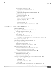
... 1-1 Cisco uBR10012 Router Features 1-2 Comparisons with Other Cisco CMTS Platforms 1-3 Cisco uBR10012 Router Functional Overview 1-3 Upstream Data Path 1-4 Downstream Data Path 1-4 Cisco uBR10012 Router and Cisco IOS Software 1-5 DOCSIS and EuroDOCSIS Data Rates and Modulation Schemes 1-5 NEBS Level 3 Compliance 1-7 Cisco uBR10012 Universal Broadband Router Hardware 1-7 Cisco uBR10012 Router 1-7 Cisco uBR10012 Router Slot Numbering 1-11 Cisco uBR10012 Universal Broadband Router Modules 1-13 Fan Assembly Module 1-13 AC Power...
... 1-1 Cisco uBR10012 Router Features 1-2 Comparisons with Other Cisco CMTS Platforms 1-3 Cisco uBR10012 Router Functional Overview 1-3 Upstream Data Path 1-4 Downstream Data Path 1-4 Cisco uBR10012 Router and Cisco IOS Software 1-5 DOCSIS and EuroDOCSIS Data Rates and Modulation Schemes 1-5 NEBS Level 3 Compliance 1-7 Cisco uBR10012 Universal Broadband Router Hardware 1-7 Cisco uBR10012 Router 1-7 Cisco uBR10012 Router Slot Numbering 1-11 Cisco uBR10012 Universal Broadband Router Modules 1-13 Fan Assembly Module 1-13 AC Power...
Hardware Installation Guide
Page 5
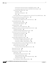
... Guidelines 2-9 Ethernet and Fast Ethernet Connections 2-10 Fiber-Optic Connections 2-10 Rack-Mounting Considerations 2-11 Mounting Guidelines 2-11 Using Power Strips with a Rack-Mount Installation 2-12 Installing the Cisco uBR10012 Router 3-1 Installation Methods 3-2 Preparing the Cisco uBR10012 Router for Rack-Mounting 3-2 General Rack Installation Guidelines 3-3 Removing the Chassis Components Before Installation 3-4 Before You Begin 3-4 Removing...
... Guidelines 2-9 Ethernet and Fast Ethernet Connections 2-10 Fiber-Optic Connections 2-10 Rack-Mounting Considerations 2-11 Mounting Guidelines 2-11 Using Power Strips with a Rack-Mount Installation 2-12 Installing the Cisco uBR10012 Router 3-1 Installation Methods 3-2 Preparing the Cisco uBR10012 Router for Rack-Mounting 3-2 General Rack Installation Guidelines 3-3 Removing the Chassis Components Before Installation 3-4 Before You Begin 3-4 Removing...
Hardware Installation Guide
Page 6
... Steps 3-31 Disconnecting Cables from the Lineage AC-DC Power Shelf and the Cisco uBR10012 Router 3-34 Connecting DC Power to the Cisco uBR10012 Router 3-34 Recommended Tools and Supplies 3-35 Connecting the Cisco uBR10012 Chassis to a DC Power Source 3-36 Connecting Alarm Indicators 3-36 Recommended Tools and...Cable Connections 3-56 Connecting a Single-Port Gigabit Ethernet Line Card 3-57 Replacing the Front Cover 3-60 Powering On the System 3-61 Configuring the Cisco uBR10012 Router at Startup 3-61 Startup Display 3-61 Basic Configuration Using the Setup Facility 3-62 System Configuration ...
... Steps 3-31 Disconnecting Cables from the Lineage AC-DC Power Shelf and the Cisco uBR10012 Router 3-34 Connecting DC Power to the Cisco uBR10012 Router 3-34 Recommended Tools and Supplies 3-35 Connecting the Cisco uBR10012 Chassis to a DC Power Source 3-36 Connecting Alarm Indicators 3-36 Recommended Tools and...Cable Connections 3-56 Connecting a Single-Port Gigabit Ethernet Line Card 3-57 Replacing the Front Cover 3-60 Powering On the System 3-61 Configuring the Cisco uBR10012 Router at Startup 3-61 Startup Display 3-61 Basic Configuration Using the Setup Facility 3-62 System Configuration ...

Hardware Installation Guide
Page 7
... Connection 4-5 Identifying Startup Problems 4-6 Troubleshooting the Power Subsystem 4-7 Troubleshooting the AC Power Subsystem 4-7 Troubleshooting the DC Power Subsystem 4-9 Troubleshooting the 2400 W AC-Input Power Shelf 4-12 Troubleshooting the Processor Subsystem 4-13 Troubleshooting the Cooling Subsystem 4-14 Troubleshooting the Line Cards 4-15 Troubleshooting the HHGE Installation 4-16 Maintaining the Cisco uBR10012 Router 5-1 Shutting Down the System 5-2 Required...
... Connection 4-5 Identifying Startup Problems 4-6 Troubleshooting the Power Subsystem 4-7 Troubleshooting the AC Power Subsystem 4-7 Troubleshooting the DC Power Subsystem 4-9 Troubleshooting the 2400 W AC-Input Power Shelf 4-12 Troubleshooting the Processor Subsystem 4-13 Troubleshooting the Cooling Subsystem 4-14 Troubleshooting the Line Cards 4-15 Troubleshooting the HHGE Installation 4-16 Maintaining the Cisco uBR10012 Router 5-1 Shutting Down the System 5-2 Required...

Hardware Installation Guide
Page 9
Contents D A P P E N D I X INDEX NTSC (M) Cable Television Channel Frequencies for Japan C-8 NTSC Cable Television Channel Frequencies for the Republic of Korea C-10 PAL/SECAM Cable Television Channels and Relative Frequencies C-14 PAL SECAM (D/K) Cable Television Channel Frequencies for the People's Republic of China C-18 Manufacturers for Hardware Components D-1 North American Channel Plans D-1 European Channel Plans D-3 Cable Kits and Tools D-4 External AC-Input Power Shelves D-5 OL-18259-09 Cisco uBR10012 Universal Broadband Router Hardware Installation Guide vii
Contents D A P P E N D I X INDEX NTSC (M) Cable Television Channel Frequencies for Japan C-8 NTSC Cable Television Channel Frequencies for the Republic of Korea C-10 PAL/SECAM Cable Television Channels and Relative Frequencies C-14 PAL SECAM (D/K) Cable Television Channel Frequencies for the People's Republic of China C-18 Manufacturers for Hardware Components D-1 North American Channel Plans D-1 European Channel Plans D-3 Cable Kits and Tools D-4 External AC-Input Power Shelves D-5 OL-18259-09 Cisco uBR10012 Universal Broadband Router Hardware Installation Guide vii

Hardware Installation Guide
Page 11
... Rear Mounting Brackets 3-17 Cisco uBR10012 Universal Broadband Router Hardware Installation Guide i Front and Rear View 1-16 Rear View of the Lineage AC-DC Power Shelf with Front Cover 1-8 Cisco uBR10012 Router Chassis-Front View without the Front Cover 1-9 Cisco uBR10012 Router Chassis-Rear View 1-10 Cisco uBR10012 Chassis Slot Numbering-Rear View 1-11 Cisco uBR10012 Chassis Slot Numbering-Front View...
... Rear Mounting Brackets 3-17 Cisco uBR10012 Universal Broadband Router Hardware Installation Guide i Front and Rear View 1-16 Rear View of the Lineage AC-DC Power Shelf with Front Cover 1-8 Cisco uBR10012 Router Chassis-Front View without the Front Cover 1-9 Cisco uBR10012 Router Chassis-Rear View 1-10 Cisco uBR10012 Chassis Slot Numbering-Rear View 1-11 Cisco uBR10012 Chassis Slot Numbering-Front View...

Hardware Installation Guide
Page 12
...= Modules 3-30 Alarm Monitor Cable 3-31 Alarm Monitor Cable with PIN and RJ-45 connectors 3-32 Alarm Monitor Cable Connected From the Lineage AC-DC Power Shelf to UBR-PWR-DC= Module 3-33 Stripping Insulation 3-37 Alarm Terminal Block Connections 3-38 Inserting the Cable Interface Line Card 3-41 Closing the Ejector... Chassis 3-60 Removing the Front Cover 5-3 Attaching the Cover to the Chassis 5-4 Removing and Inserting the Air Filter 5-5 Air Filter Inserted into the Front Cover 5-6 Cisco uBR10012 Universal Broadband Router Hardware Installation Guide ii OL-18259-09
...= Modules 3-30 Alarm Monitor Cable 3-31 Alarm Monitor Cable with PIN and RJ-45 connectors 3-32 Alarm Monitor Cable Connected From the Lineage AC-DC Power Shelf to UBR-PWR-DC= Module 3-33 Stripping Insulation 3-37 Alarm Terminal Block Connections 3-38 Inserting the Cable Interface Line Card 3-41 Closing the Ejector... Chassis 3-60 Removing the Front Cover 5-3 Attaching the Cover to the Chassis 5-4 Removing and Inserting the Air Filter 5-5 Air Filter Inserted into the Front Cover 5-6 Cisco uBR10012 Universal Broadband Router Hardware Installation Guide ii OL-18259-09

Hardware Installation Guide
Page 15
... 2.0 Upstream Data Rates 1-6 DOCSIS and EuroDOCSIS Downstream Data Rates 1-6 Specifications of the DC PEM modules 1-14 Supported External Power Shelves for Cisco uBR10012 Router Specifications 1-15 Cisco uBR10012 Router DC PEM Modules and Lineage Shelves 1-15 Cisco PRE LEDs and Cutoff Switch 1-23 Gigabit Ethernet Line Card LEDs and Their Functions 1-30 GBIC Port Cabling Specifications...
... 2.0 Upstream Data Rates 1-6 DOCSIS and EuroDOCSIS Downstream Data Rates 1-6 Specifications of the DC PEM modules 1-14 Supported External Power Shelves for Cisco uBR10012 Router Specifications 1-15 Cisco uBR10012 Router DC PEM Modules and Lineage Shelves 1-15 Cisco PRE LEDs and Cutoff Switch 1-23 Gigabit Ethernet Line Card LEDs and Their Functions 1-30 GBIC Port Cabling Specifications...

Hardware Installation Guide
Page 16
... Provisioning Requirements D-1 Manufacturers for North American Headend Measurement Devices D-2 Manufacturers for European Headend Provisioning Requirements D-3 Manufacturers for European Headend Measurement Devices D-4 Tool Manufactures D-4 AC-input Power Shelves Manufactures D-5 Cisco uBR10012 Universal Broadband Router Hardware Installation Guide ii OL-18259-09
... Provisioning Requirements D-1 Manufacturers for North American Headend Measurement Devices D-2 Manufacturers for European Headend Provisioning Requirements D-3 Manufacturers for European Headend Measurement Devices D-4 Tool Manufactures D-4 AC-input Power Shelves Manufactures D-5 Cisco uBR10012 Universal Broadband Router Hardware Installation Guide ii OL-18259-09

Hardware Installation Guide
Page 17
...=), 3300 W AC PEM (UBR10-PWR-AC-PLUS=), and 3300 W DC PEM module. Updated with the updated DC PEM power specifications. OL-18259-09 Cisco uBR10012 Universal Broadband Router Hardware Installation Guide i Document Revision History Date 11/10/2011 20/06/2011 29/04/2011 10/03/...18259-01 78-11450-03 Rev.B0 Reason Added instructions on cabling and connecting the Lineage power shelf to the UBR10-PWR-DC-PLUS= power entry module on cabling the shelf to the Cisco uBR10012 chassis. Added Cisco UBR-MC3GX60V cable interface line card information. Added table 2-2 and Table A-1 with PRE4...
...=), 3300 W AC PEM (UBR10-PWR-AC-PLUS=), and 3300 W DC PEM module. Updated with the updated DC PEM power specifications. OL-18259-09 Cisco uBR10012 Universal Broadband Router Hardware Installation Guide i Document Revision History Date 11/10/2011 20/06/2011 29/04/2011 10/03/...18259-01 78-11450-03 Rev.B0 Reason Added instructions on cabling and connecting the Lineage power shelf to the UBR10-PWR-DC-PLUS= power entry module on cabling the shelf to the Cisco uBR10012 chassis. Added Cisco UBR-MC3GX60V cable interface line card information. Added table 2-2 and Table A-1 with PRE4...

Hardware Installation Guide
Page 24
... integrated 256-KB Level 2 cache, and 4-MB Level 3 cache. Cisco uBR10012 Router Features Chapter 1 Cisco uBR10012 Universal Broadband Router Overview Cisco uBR10012 Router Features The Cisco uBR10012 router has the following URL: http://www.cisco.com/en/US/docs/cable/cmts/ubr10012/installation/field_replaceable_units/pr e2gkit.html • AC and DC power supply options: - A high availability N+1 enabled system with a second connector...
... integrated 256-KB Level 2 cache, and 4-MB Level 3 cache. Cisco uBR10012 Router Features Chapter 1 Cisco uBR10012 Universal Broadband Router Overview Cisco uBR10012 Router Features The Cisco uBR10012 router has the following URL: http://www.cisco.com/en/US/docs/cable/cmts/ubr10012/installation/field_replaceable_units/pr e2gkit.html • AC and DC power supply options: - A high availability N+1 enabled system with a second connector...

Hardware Installation Guide
Page 29
...the following categories: • Filtration and front to DC power for the Cisco uBR10012 router. A rack-mount kit ships from the Cisco factory with optional third-party mounting hardware. OL-18259-09 Cisco uBR10012 Universal Broadband Router Hardware Installation Guide 1-7 The rack-mount... immunity • Electrical safety • EMI emissions and immunity Cisco uBR10012 Universal Broadband Router Hardware This section describes the Cisco uBR10012 router and router components. Note If the only available power supply source is possible with each router. Mounting in 23-inch...
...the following categories: • Filtration and front to DC power for the Cisco uBR10012 router. A rack-mount kit ships from the Cisco factory with optional third-party mounting hardware. OL-18259-09 Cisco uBR10012 Universal Broadband Router Hardware Installation Guide 1-7 The rack-mount... immunity • Electrical safety • EMI emissions and immunity Cisco uBR10012 Universal Broadband Router Hardware This section describes the Cisco uBR10012 router and router components. Note If the only available power supply source is possible with each router. Mounting in 23-inch...

Hardware Installation Guide
Page 30
... IPSUM SSLLOOTT01 AUX CONSOLE AUX CONSOLE CISCO 10000 CISCO 10000 POWER MISWIRE FAULT POWER MISWIRE FAULT ACTIVITYETHERLNINEKT SSLLOOTT01 ACTIVITEYTHERLNINETK ALARMS ALARMS ACO ACO CRITICAML AJOR MINOR CRITICAML AJOR MINOR PERFORMANCE ROUTING ENGINE PERFORMANCE ROUTING ENGINE STATUSFAIL STATUSFAIL 56300 Cisco uBR10012 Universal Broadband Router Hardware Installation Guide 1-8 OL-18259-09 Figure 1-1 Cisco uBR10012 Universal Broadband Router-Front View with...
... IPSUM SSLLOOTT01 AUX CONSOLE AUX CONSOLE CISCO 10000 CISCO 10000 POWER MISWIRE FAULT POWER MISWIRE FAULT ACTIVITYETHERLNINEKT SSLLOOTT01 ACTIVITEYTHERLNINETK ALARMS ALARMS ACO ACO CRITICAML AJOR MINOR CRITICAML AJOR MINOR PERFORMANCE ROUTING ENGINE PERFORMANCE ROUTING ENGINE STATUSFAIL STATUSFAIL 56300 Cisco uBR10012 Universal Broadband Router Hardware Installation Guide 1-8 OL-18259-09 Figure 1-1 Cisco uBR10012 Universal Broadband Router-Front View with...

Hardware Installation Guide
Page 31
Figure 1-2 Cisco uBR10012 Router Chassis-Front View without the front cover. Note Figure 1-2 is a sample representation of a fully loaded chassis without the Front Cover 1 CONSOLE 2 CISCO 10000 CISCO 10000 POWER MISWIRE FAULT CONSOLE POWER MISWIRE FAULT AUX AUX ACTIVITYETHERLNINEKT SSLLOOTT01 ACTIVITEYTHERLNINETK SSLLOOTT01 4 3 ALARMS ALARMS ACO ACO CRITICAML AJOR MINOR CRITICAML AJOR MINOR PERFORMANCE ROUTING ENGINE PERFORMANCE ROUTING...
Figure 1-2 Cisco uBR10012 Router Chassis-Front View without the front cover. Note Figure 1-2 is a sample representation of a fully loaded chassis without the Front Cover 1 CONSOLE 2 CISCO 10000 CISCO 10000 POWER MISWIRE FAULT CONSOLE POWER MISWIRE FAULT AUX AUX ACTIVITYETHERLNINEKT SSLLOOTT01 ACTIVITEYTHERLNINETK SSLLOOTT01 4 3 ALARMS ALARMS ACO ACO CRITICAML AJOR MINOR CRITICAML AJOR MINOR PERFORMANCE ROUTING ENGINE PERFORMANCE ROUTING...

Hardware Installation Guide
Page 32
... cards not shown) Caution The handles shown on the left and right sides of a fully-loaded Cisco uBR10012 router. Cisco uBR10012 Universal Broadband Router Hardware Chapter 1 Cisco uBR10012 Universal Broadband Router Overview Figure 1-3 shows the rear of the chassis should be used only when lifting..., fan assembly module, or line cards installed. Figure 1-3 Cisco uBR10012 Router Chassis-Rear View uBR10-MC5x20S-D uBR10-MC5x20S-D uBR10-MC5x20S-D uBR10-MC5x20S-D uBR10-MC5x20S-D uBR10-MC5x20S-D uBR10-MC5x20S-D uBR10-MC5x20S-D POWER STATUS MAINT POW ER STATUS MAINT POW ER STATUS MAINT POW...
... cards not shown) Caution The handles shown on the left and right sides of a fully-loaded Cisco uBR10012 router. Cisco uBR10012 Universal Broadband Router Hardware Chapter 1 Cisco uBR10012 Universal Broadband Router Overview Figure 1-3 shows the rear of the chassis should be used only when lifting..., fan assembly module, or line cards installed. Figure 1-3 Cisco uBR10012 Router Chassis-Rear View uBR10-MC5x20S-D uBR10-MC5x20S-D uBR10-MC5x20S-D uBR10-MC5x20S-D uBR10-MC5x20S-D uBR10-MC5x20S-D uBR10-MC5x20S-D uBR10-MC5x20S-D POWER STATUS MAINT POW ER STATUS MAINT POW ER STATUS MAINT POW...

Hardware Installation Guide
Page 33
...uBR10-MC5x20S-D uBR10-MC5x20S-D uBR10-MC5x20S-D uBR10-MC5x20S-D uBR10-MC5x20S-D POW ER STATUS MAINT POWER STATUS MAINT POW ER STATUS MAINT POWER STATUS MAINT POWER STATUS MAINT POW ER STATUS MAINT POW ER STATUS MAINT POW ER STATUS MAINT US0 US1 ...slot splitter that subdivides the slots so that they become slots 3/0/0, 3/0/1, and slots 4/0/0, 4/0/1. Chapter 1 Cisco uBR10012 Universal Broadband Router Overview Cisco uBR10012 Universal Broadband Router Hardware Cisco uBR10012 Router Slot Numbering Figure 1-4 shows the slot numbering for the line cards and TCC+ cards in the ...
...uBR10-MC5x20S-D uBR10-MC5x20S-D uBR10-MC5x20S-D uBR10-MC5x20S-D uBR10-MC5x20S-D POW ER STATUS MAINT POWER STATUS MAINT POW ER STATUS MAINT POWER STATUS MAINT POWER STATUS MAINT POW ER STATUS MAINT POW ER STATUS MAINT POW ER STATUS MAINT US0 US1 ...slot splitter that subdivides the slots so that they become slots 3/0/0, 3/0/1, and slots 4/0/0, 4/0/1. Chapter 1 Cisco uBR10012 Universal Broadband Router Overview Cisco uBR10012 Universal Broadband Router Hardware Cisco uBR10012 Router Slot Numbering Figure 1-4 shows the slot numbering for the line cards and TCC+ cards in the ...

Hardware Installation Guide
Page 34
Figure 1-5 Cisco uBR10012 Chassis Slot Numbering-Front View CISCO 10000 CISCO 10000 CONSOLE AUX SSLLOOTT01 ACTIVITEYTHERLNINETK SSLLOOTT01 FastEthernet slot 0/0 (on active PRE1) ACTIVITYETHERLNINEKT AUX CONSOLE POWER MISWIRE FAULT POWER MISWIRE FAULT ALARMS ALARMS ACO ACO CRITICAML AJOR MINOR CRITICAML AJOR MINOR PERFORMANCE ROUTING ENGINE PERFORMANCE ROUTING ENGINE STATUSFAIL STATUSFAIL 56470 Tip The Fast Ethernet ...
Figure 1-5 Cisco uBR10012 Chassis Slot Numbering-Front View CISCO 10000 CISCO 10000 CONSOLE AUX SSLLOOTT01 ACTIVITEYTHERLNINETK SSLLOOTT01 FastEthernet slot 0/0 (on active PRE1) ACTIVITYETHERLNINEKT AUX CONSOLE POWER MISWIRE FAULT POWER MISWIRE FAULT ALARMS ALARMS ACO ACO CRITICAML AJOR MINOR CRITICAML AJOR MINOR PERFORMANCE ROUTING ENGINE PERFORMANCE ROUTING ENGINE STATUSFAIL STATUSFAIL 56470 Tip The Fast Ethernet ...

Hardware Installation Guide
Page 35
... the Cisco uBR10012 Universal Broadband Router. Chapter 1 Cisco uBR10012 Universal Broadband Router Overview Cisco uBR10012 Universal Broadband Router Modules Cisco uBR10012 Universal Broadband Router Modules The following section describes the modules used in the Cisco uBR10012 router. The two AC PEMs convert the AC power to provide filtered, redundant, and load shared DC power to the chassis. AC Power Entry Modules The Cisco uBR10012 router...
... the Cisco uBR10012 Universal Broadband Router. Chapter 1 Cisco uBR10012 Universal Broadband Router Overview Cisco uBR10012 Universal Broadband Router Modules Cisco uBR10012 Universal Broadband Router Modules The following section describes the modules used in the Cisco uBR10012 router. The two AC PEMs convert the AC power to provide filtered, redundant, and load shared DC power to the chassis. AC Power Entry Modules The Cisco uBR10012 router...

Hardware Installation Guide
Page 36
...-60 VDC nominal -57.5 V -48 to -60 VDC -55 to the Cisco uBR10012 chassis. The allowable DC-input range is -40.5 V to the 3300 W DC PEM, see DC Power Entry Module for these DC PEM modules. For information on installing, removing and replacing ... and is not constant for the Cisco uBR10012 Universal Broadband Router. Cisco uBR10012 Universal Broadband Router Modules Chapter 1 Cisco uBR10012 Universal Broadband Router Overview DC Power Entry Modules The Cisco uBR10012 router is shipped with two DC power entry modules (DC PEMs) that provide power to the DC-input voltage with ...
...-60 VDC nominal -57.5 V -48 to -60 VDC -55 to the Cisco uBR10012 chassis. The allowable DC-input range is -40.5 V to the 3300 W DC PEM, see DC Power Entry Module for these DC PEM modules. For information on installing, removing and replacing ... and is not constant for the Cisco uBR10012 Universal Broadband Router. Cisco uBR10012 Universal Broadband Router Modules Chapter 1 Cisco uBR10012 Universal Broadband Router Overview DC Power Entry Modules The Cisco uBR10012 router is shipped with two DC power entry modules (DC PEMs) that provide power to the DC-input voltage with ...

Hardware Installation Guide
Page 37
... recommend you use the external AC-input power shelf with the Cisco uBR10012 router The AC-input power shelf converts AC power from Lineage (part number J85480S1 L30) with the Cisco uBR10012 router chassis. Lineage AC-DC Power Shelf This external AC-DC power shelf from an external AC power supply source into DC power that are : • 2400 W AC-Input...
... recommend you use the external AC-input power shelf with the Cisco uBR10012 router The AC-input power shelf converts AC power from Lineage (part number J85480S1 L30) with the Cisco uBR10012 router chassis. Lineage AC-DC Power Shelf This external AC-DC power shelf from an external AC power supply source into DC power that are : • 2400 W AC-Input...


