User Guide
Page 4
... Set Time 22 Local Time 22 Daylight Saving 22 SNTP Servers 22 Setup > Green Ethernet 23 Port Management > Port Settings 23 Port Settings > Port Configuration 24 Port Management > Link Aggregation 25 Link Aggregation > Detail 25 Port Management > LACP 26 VLAN Management > Create VLAN 26 Single VLAN 26 VLAN Range 26 VLAN Table 26 VLAN...
... Set Time 22 Local Time 22 Daylight Saving 22 SNTP Servers 22 Setup > Green Ethernet 23 Port Management > Port Settings 23 Port Settings > Port Configuration 24 Port Management > Link Aggregation 25 Link Aggregation > Detail 25 Port Management > LACP 26 VLAN Management > Create VLAN 26 Single VLAN 26 VLAN Range 26 VLAN Table 26 VLAN...
User Guide
Page 8
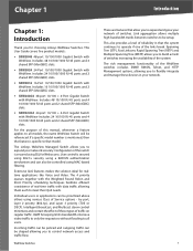
The Linksys WebView Managed Switch allows you to expand and grow your network of this manual, whenever a feature applies to all users. Includes 16 10/100/1000 RJ-45 ... Linkover, Rapid Spanning Tree (RSTP) and Multiple Spanning Tree (MSTP) allows you to flexibly integrate and manage these types of the system. The rich management functionality of the WebView switches includes SNMP, RMON, Telnet, and HTTP Management options, allowing you to build a mesh of switches increasing the availability of traffic on regular traffic...
The Linksys WebView Managed Switch allows you to expand and grow your network of this manual, whenever a feature applies to all users. Includes 16 10/100/1000 RJ-45 ... Linkover, Rapid Spanning Tree (RSTP) and Multiple Spanning Tree (MSTP) allows you to flexibly integrate and manage these types of the system. The rich management functionality of the WebView switches includes SNMP, RMON, Telnet, and HTTP Management options, allowing you to build a mesh of switches increasing the availability of traffic on regular traffic...

User Guide
Page 10
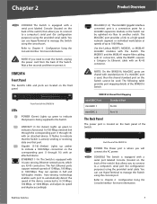
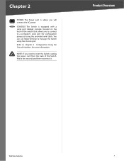
... power cord from the back of the SRW2024 POWER The Power port is equipped with 24 auto-sensing Ethernet network ports, which use HyperTerminal to manage the Switch using the provided serial cable. Back Panel of the Switch.
... power cord from the back of the SRW2024 POWER The Power port is equipped with 24 auto-sensing Ethernet network ports, which use HyperTerminal to manage the Switch using the provided serial cable. Back Panel of the Switch.
User Guide
Page 11
...cable. Refer to Chapter 4: Configuration Using the Console Interface for a miniGBIC expansion module, so the Switch can use HyperTerminal to another switch. Refer to manage the Switch using the console port. Back Panel of the SRW2016 POWER The Power port is located on the back panel of the Switch. You... can be used , then the shared standard port on the Switch cannot be uplinked via fiber to manage the Switch using the console port. SRW2016 Front Panel The Switch's LEDs and ports are shared with standard ports. Wait a few seconds and ...
...cable. Refer to Chapter 4: Configuration Using the Console Interface for a miniGBIC expansion module, so the Switch can use HyperTerminal to another switch. Refer to manage the Switch using the console port. Back Panel of the SRW2016 POWER The Power port is located on the back panel of the Switch. You... can be used , then the shared standard port on the Switch cannot be uplinked via fiber to manage the Switch using the console port. SRW2016 Front Panel The Switch's LEDs and ports are shared with standard ports. Wait a few seconds and ...
User Guide
Page 13
... its speed and duplex accordingly. Use the Linksys MGBT1, MGBSX1, or MGBLH1 miniGBIC modules with 24 auto-sensing, Ethernet network ports, which use HyperTerminal to manage the Switch using the provided serial cable. It flashes to indicate that the Switch is actively sending or receiving data over that power is being...
... its speed and duplex accordingly. Use the Linksys MGBT1, MGBSX1, or MGBLH1 miniGBIC modules with 24 auto-sensing, Ethernet network ports, which use HyperTerminal to manage the Switch using the provided serial cable. It flashes to indicate that the Switch is actively sending or receiving data over that power is being...
User Guide
Page 14
Refer to a computer's serial port (for more information. CONSOLE The Switch is where you need to manage the Switch using the provided serial cable. You can use HyperTerminal to reset the Switch, unplug the power cord from the back of the switch) ...
Refer to a computer's serial port (for more information. CONSOLE The Switch is where you need to manage the Switch using the provided serial cable. You can use HyperTerminal to reset the Switch, unplug the power cord from the back of the switch) ...

User Guide
Page 17
... Using the Console Interface Chapter 4: Configuration Using the Console Interface Overview The Switch features a menu-driven console interface for basic configuration of the Switch and management of connection is covered in the User Name field. The Switch can also be configured using the console interface, configure the HyperTerminal application on your...
... Using the Console Interface Chapter 4: Configuration Using the Console Interface Overview The Switch features a menu-driven console interface for basic configuration of the Switch and management of connection is covered in the User Name field. The Switch can also be configured using the console interface, configure the HyperTerminal application on your...
User Guide
Page 18
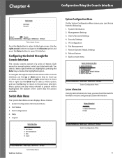
...Menu On the System Configuration Menu screen, you can check the Switch's firmware versions and general system information. Security Settings 5. File Management 7. To navigate through the Console Interface The console screens consist of a series of menus. Port Configuration 4. System Information 2. ...key to return to main menu System Configuration Menu System Information Using System Information screen, you highlight it; Port Status 3. Management Settings 3. Back to the previous selection. Help 5. System Configuration Menu Switch Main Menu WebView Switches 11 You select a...
...Menu On the System Configuration Menu screen, you can check the Switch's firmware versions and general system information. Security Settings 5. File Management 7. To navigate through the Console Interface The console screens consist of a series of menus. Port Configuration 4. System Information 2. ...key to return to main menu System Configuration Menu System Information Using System Information screen, you highlight it; Port Status 3. Management Settings 3. Back to the previous selection. Help 5. System Configuration Menu Switch Main Menu WebView Switches 11 You select a...

User Guide
Page 19
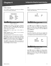
Management Settings From the Management Settings screen, you can set the following options: •• Serial Port Session Configuration •• Telnet Session Configuration •• Secure Telnet (SSH... information about the Switch. Chapter 4 Configuration Using the Console Interface Versions The Versions screen displays the Switch's boot, software, and hardware firmware versions. Management Settings Menu Serial Port Configuration The Serial Port Configuration screen displays the Switch's baud rate. General System Information Select Edit and press the Enter key...
Management Settings From the Management Settings screen, you can set the following options: •• Serial Port Session Configuration •• Telnet Session Configuration •• Secure Telnet (SSH... information about the Switch. Chapter 4 Configuration Using the Console Interface Versions The Versions screen displays the Switch's boot, software, and hardware firmware versions. Management Settings Menu Serial Port Configuration The Serial Port Configuration screen displays the Switch's baud rate. General System Information Select Edit and press the Enter key...

User Guide
Page 22
... from the Security Settings screen. Security Settings NOTE: This setting has no effect when Management Access Rules are prompted for confirmation. You are not defined. Chapter 4 Configuration Using the Console Interface SSL Certificate Generation Use the Certificate Generation screen to ...
... from the Security Settings screen. Security Settings NOTE: This setting has no effect when Management Access Rules are prompted for confirmation. You are not defined. Chapter 4 Configuration Using the Console Interface SSL Certificate Generation Use the Certificate Generation screen to ...
User Guide
Page 23
... is displayed. HTTPS Configuration The HTTPS Configuration screen lets you configure the Switch's IP address information. To exit, select Quit and press the Enter key. Management VLAN The VLAN ID number is displayed. When your network's default gateway is displayed. WebView Switches 16 Subnet Mask The subnet mask of the DHCP...
... is displayed. HTTPS Configuration The HTTPS Configuration screen lets you configure the Switch's IP address information. To exit, select Quit and press the Enter key. Management VLAN The VLAN ID number is displayed. When your network's default gateway is displayed. WebView Switches 16 Subnet Mask The subnet mask of the DHCP...

User Guide
Page 25
...On the Switch Main Menu screen, select Port Status and press the Enter key if you want to return to continue. Reboot System File Management Select Edit to upload or download files, such as the startup configuration, boot, or image file, using a TFTP server. Chapter 4 ...Configuration Using the Console Interface File Management The File Management screen allows you to change any settings for the Switch's ports. Port Status The Port Status screen displays the port numbers, their status,...
...On the Switch Main Menu screen, select Port Status and press the Enter key if you want to return to continue. Reboot System File Management Select Edit to upload or download files, such as the startup configuration, boot, or image file, using a TFTP server. Chapter 4 ...Configuration Using the Console Interface File Management The File Management screen allows you to change any settings for the Switch's ports. Port Status The Port Status screen displays the port numbers, their status,...
User Guide
Page 27
... shown in this address, enter the correct IP address. The screen images were taken from the Web-based Utility: Setup, Port Management, VLAN Management, Statistics, ACL, Security, QoS (Quality of the main tabs to configure the device. Accessing the Web-based Utility NOTE: The....168.1.254 into the Address field. Grey Indicates no connection. The port LEDs display different status information, as the management station used to view additional tabs. Chapter 5 Advanced Configuration Chapter 5: Advanced Configuration Overview This chapter describes the features included in the ...
... shown in this address, enter the correct IP address. The screen images were taken from the Web-based Utility: Setup, Port Management, VLAN Management, Statistics, ACL, Security, QoS (Quality of the main tabs to configure the device. Accessing the Web-based Utility NOTE: The....168.1.254 into the Address field. Grey Indicates no connection. The port LEDs display different status information, as the management station used to view additional tabs. Chapter 5 Advanced Configuration Chapter 5: Advanced Configuration Overview This chapter describes the features included in the ...
User Guide
Page 28
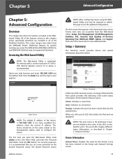
...the names of where the Switch is DHCP. Base MAC Address Displays the physical address of the gateway router between the Switch and management stations on other network segments. A second DNS address can be configured from the Setup tab's Network Settings screen. Chapter 5 ... Subnet Mask The Subnet Mask assigned to the Switch. Current Time Displays the current time. Subnet Mask If you to select the Management VLAN. Address Mode Specifies whether IP functionality is enabled via manual configuration (Static) or Dynamic Host Configuration Protocol (DHCP). System Object...
...the names of where the Switch is DHCP. Base MAC Address Displays the physical address of the gateway router between the Switch and management stations on other network segments. A second DNS address can be configured from the Setup tab's Network Settings screen. Chapter 5 ... Subnet Mask The Subnet Mask assigned to the Switch. Current Time Displays the current time. Subnet Mask If you to select the Management VLAN. Address Mode Specifies whether IP functionality is enabled via manual configuration (Static) or Dynamic Host Configuration Protocol (DHCP). System Object...
User Guide
Page 30
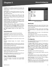
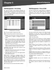
...MDIX setting is used if the port is not comprimised, while at a time). It is connected to enable energy-efficient Ethernet (EEE). Port Management > Port Settings The Port Settings screen shows you to a hub or another switch. Setup > Green Ethernet Energy Saving Mode Indicates if Green...8226;• Enable Enables Green Ethernet on Link Aggregation Groups (LAGs). Type The port type. Green Ethernet ensures that port. WebView Switches Port Management > Port Settings Port The port number. To take the port offline, select the Down option. The speed can be configured only when ...
...MDIX setting is used if the port is not comprimised, while at a time). It is connected to enable energy-efficient Ethernet (EEE). Port Management > Port Settings The Port Settings screen shows you to a hub or another switch. Setup > Green Ethernet Energy Saving Mode Indicates if Green...8226;• Enable Enables Green Ethernet on Link Aggregation Groups (LAGs). Type The port type. Green Ethernet ensures that port. WebView Switches Port Management > Port Settings Port The port number. To take the port offline, select the Down option. The speed can be configured only when ...

User Guide
Page 32
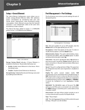
... Admin Speed The configured speed at which this checkbox to enable or disable the LAG. LAG (Read-only) The LAG to 64 characters. Port Management > Link Aggregation Port Management > Link Aggregation LAG The LAG number (1-8). Description The user-defined LAG description of the LAG. LACP Select the checkbox to save the settings...
... Admin Speed The configured speed at which this checkbox to enable or disable the LAG. LAG (Read-only) The LAG to 64 characters. Port Management > Link Aggregation Port Management > Link Aggregation LAG The LAG number (1-8). Description The user-defined LAG description of the LAG. LACP Select the checkbox to save the settings...
User Guide
Page 33
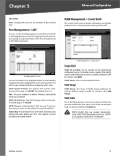
...field is 1. LACP Port Priority The LACP priority value for configuring LACP LAGs. This only applies to add VLANs one at a time. VLAN Management > Create VLAN Single VLAN VLAN ID (2-4094) The ID number of ports with VLANs. Port The port number to 256 VLANs can be ... the defined range of all configured VLANs. Each group is the default. Up to which timeout and priority values are displayed here. VLAN Management > Create VLAN The Create VLAN screen provides information and global parameters for configuring and working with the same speed, set up aggregated links ...
...field is 1. LACP Port Priority The LACP priority value for configuring LACP LAGs. This only applies to add VLANs one at a time. VLAN Management > Create VLAN Single VLAN VLAN ID (2-4094) The ID number of ports with VLANs. Port The port number to 256 VLANs can be ... the defined range of all configured VLANs. Each group is the default. Up to which timeout and priority values are displayed here. VLAN Management > Create VLAN The Create VLAN screen provides information and global parameters for configuring and working with the same speed, set up aggregated links ...
User Guide
Page 34
... the packet types which all ports are accepted on the port. •• Admit Tag Only Indicates that can be untagged. WebView Switches VLAN Management > Ports to VLAN The Ports to a VLAN. When a port is also not possible to enable or disable ingress filtering on the port. ...4095 is configured on the port cannot be added to VLANs, and each VLAN is defined. However, the interface cannot be designated. VLAN Management > Ports to VLAN The Ports to VLAN screen contains fields for configuring ports to VLAN screen contains a Port Table for VLAN parameters for ...
... the packet types which all ports are accepted on the port. •• Admit Tag Only Indicates that can be untagged. WebView Switches VLAN Management > Ports to VLAN The Ports to a VLAN. When a port is also not possible to enable or disable ingress filtering on the port. ...4095 is configured on the port cannot be added to VLANs, and each VLAN is defined. However, the interface cannot be designated. VLAN Management > Ports to VLAN The Ports to VLAN screen contains fields for configuring ports to VLAN screen contains a Port Table for VLAN parameters for ...

User Guide
Page 35
...field definitions for both areas are tagged, except for one port that can be designated. Interface Displays the interface on the device. VLAN Management > GVRP The Global System LAG information displays the same field information as tagged or untagged (full 802.1Q mode). •• ... GVRP setting to individually configure each VLAN is user-defined as the ports, but represents the LAG GVRP information. WebView Switches 28 VLAN Management > GVRP GARP VLAN Registration Protocol (GVRP) is enabled. The possible field values are: •• Port Indicates the port number ...
...field definitions for both areas are tagged, except for one port that can be designated. Interface Displays the interface on the device. VLAN Management > GVRP The Global System LAG information displays the same field information as tagged or untagged (full 802.1Q mode). •• ... GVRP setting to individually configure each VLAN is user-defined as the ports, but represents the LAG GVRP information. WebView Switches 28 VLAN Management > GVRP GARP VLAN Registration Protocol (GVRP) is enabled. The possible field values are: •• Port Indicates the port number ...
User Guide
Page 38
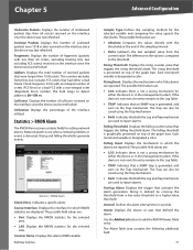
...FCS octets that activates the alarm generation. Statistics > RMON Alarm The RMON Alarm screen contains fields for either the device or in the management system. Each monitored variable is designated a color. Use the Add to List button to report alarms. Falling Threshold Displays the falling counter ...from the current value. The field range to report alarms. Startup Alarm Displays the trigger that had either the device or in the management system. Counter Name Displays the selected MIB variable. The rising threshold is 20-150 ms. Collisions Displays the number of the graph...
...FCS octets that activates the alarm generation. Statistics > RMON Alarm The RMON Alarm screen contains fields for either the device or in the management system. Each monitored variable is designated a color. Use the Add to List button to report alarms. Falling Threshold Displays the falling counter ...from the current value. The field range to report alarms. Startup Alarm Displays the trigger that had either the device or in the management system. Counter Name Displays the selected MIB variable. The rising threshold is 20-150 ms. Collisions Displays the number of the graph...


