

Administration Guide
Page 3
... Ports Uplink Ports The Back Panel Power Port Console Port RPS Port 3 3 3 3 4 4 4 5 5 6 6 6 7 7 Chapter 3: Connecting the Switch 8 Overview 8 Before You Install the Switch... 8 Placement Options 9 Desktop Placement 9 Rack-Mount Placement 9 Wall-Mount Placement 10 Connecting the Cables 11 Stacking Multiple Switches 12 Connecting Cabling for Stacking 13 Managing Stacks 14 Building Automatically-Configured Stacks 14 Building...
... Ports Uplink Ports The Back Panel Power Port Console Port RPS Port 3 3 3 3 4 4 4 5 5 6 6 6 7 7 Chapter 3: Connecting the Switch 8 Overview 8 Before You Install the Switch... 8 Placement Options 9 Desktop Placement 9 Rack-Mount Placement 9 Wall-Mount Placement 10 Connecting the Cables 11 Stacking Multiple Switches 12 Connecting Cabling for Stacking 13 Managing Stacks 14 Building Automatically-Configured Stacks 14 Building...

Administration Guide
Page 4
... Units into a Stack 31 Inserting a Standalone Unit into a Running Stack 32 Chapter 4: Console Configuration 33 Overview 33 Configuring the HyperTerminal Application 33 Connecting to the Switch using Telnet or SSH 35 Configuring the Switch through the Console or Telnet Interface 35 Switch Main Menu 36 Chapter 5: Web Utility Configuration Overview Accessing the Web-based Utility...
... Units into a Stack 31 Inserting a Standalone Unit into a Running Stack 32 Chapter 4: Console Configuration 33 Overview 33 Configuring the HyperTerminal Application 33 Connecting to the Switch using Telnet or SSH 35 Configuring the Switch through the Console or Telnet Interface 35 Switch Main Menu 36 Chapter 5: Web Utility Configuration Overview Accessing the Web-based Utility...
Administration Guide
Page 6
... devices, and significantly decreasing installation costs. Twenty four ports wire up , and configure it is fully manageable using the Ethernet switch. The "P" model of the Ethernet switch supports Power over Ethernet (PoE) which eliminates the need to other PoE powered devices on the Linksys ...'s in locations of its attached networks. Refer to quickly and easily expand your web browser, or the console interface. Linksys One Portal The Ethernet switch features monitoring and configuration via the Linksys One Portal, your Linksys One system. The entire PoE system can...
... devices, and significantly decreasing installation costs. Twenty four ports wire up , and configure it is fully manageable using the Ethernet switch. The "P" model of the Ethernet switch supports Power over Ethernet (PoE) which eliminates the need to other PoE powered devices on the Linksys ...'s in locations of its attached networks. Refer to quickly and easily expand your web browser, or the console interface. Linksys One Portal The Ethernet switch features monitoring and configuration via the Linksys One Portal, your Linksys One system. The entire PoE system can...

Administration Guide
Page 7
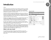
... 5, "Web Utility Configuration" This chapter shows you configure the Ethernet switch. Chapter Linksys One Ready Communications Solution 1 This user guide contains the following chapters: Chapter 1, "Introduction" This chapter describes the Ethernet switch applications and provides an overview of the content of the Ethernet switch. Chapter 4, "Console Configuration" This chapter describes how to Know the...
... 5, "Web Utility Configuration" This chapter shows you configure the Ethernet switch. Chapter Linksys One Ready Communications Solution 1 This user guide contains the following chapters: Chapter 1, "Introduction" This chapter describes the Ethernet switch applications and provides an overview of the content of the Ethernet switch. Chapter 4, "Console Configuration" This chapter describes how to Know the...

Administration Guide
Page 11
The mini-GBIC port is a connection point for configuration. Console Port. Redundant Power Supply (RPS) port. Chapter Linksys One Ready Communications Solution 2 Uplink Ports The Switch is equipped with the Switch. GBIC1-4 The Switch provides four mini-GBIC ports. Use the Linksys MGBT1, MGBSX1, ..., refer to a high-speed network segment or individual workstation at speeds of the Ethernet switch. 1 2 3 Power Port. The Console port is where you can 2 connect a serial cable to another switch. Chapter 2: Getting to the Power port. Each mini-GBIC port provides a link to...
The mini-GBIC port is a connection point for configuration. Console Port. Redundant Power Supply (RPS) port. Chapter Linksys One Ready Communications Solution 2 Uplink Ports The Switch is equipped with the Switch. GBIC1-4 The Switch provides four mini-GBIC ports. Use the Linksys MGBT1, MGBSX1, ..., refer to a high-speed network segment or individual workstation at speeds of the Ethernet switch. 1 2 3 Power Port. The Console port is where you can 2 connect a serial cable to another switch. Chapter 2: Getting to the Power port. Each mini-GBIC port provides a link to...

Administration Guide
Page 12
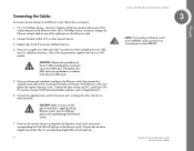
...the RPS port. WARNING: Do not remove the cover from the RPS port unless an RPS unit is connected to the console serial port. Chapter Console Port The Console port is where you connect a serial cable to a PC's serial port for more information. Refer to "Configuring the ...HyperTerminal Application," on your PC's HyperTerminal program. An RPS enhances the reliability of the Ethernet switch and it can keep the unit running ...
...the RPS port. WARNING: Do not remove the cover from the RPS port unless an RPS unit is connected to the console serial port. Chapter Console Port The Console port is where you connect a serial cable to a PC's serial port for more information. Refer to "Configuring the ...HyperTerminal Application," on your PC's HyperTerminal program. An RPS enhances the reliability of the Ethernet switch and it can keep the unit running ...
Administration Guide
Page 16
... that is supplied with the mini-GBIC module. If you are upside down in relation to connect additional devices. 4. CAUTION: Make sure you use the console interface to configure the Ethernet switch, then connect the supplied serial cable to one of the numbered ports on the Ethernet... switch. For a 1000Mbps device, connect a Category 5e Ethernet network cable to the console port (located on the back of the uplink ports on the network devices connected to your PC's serial port. (The PC must be running ...
... that is supplied with the mini-GBIC module. If you are upside down in relation to connect additional devices. 4. CAUTION: Make sure you use the console interface to configure the Ethernet switch, then connect the supplied serial cable to one of the numbered ports on the Ethernet... switch. For a 1000Mbps device, connect a Category 5e Ethernet network cable to the console port (located on the back of the uplink ports on the network devices connected to your PC's serial port. (The PC must be running ...
Administration Guide
Page 17
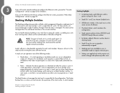
... run the same version of the stack master. A switch operating in the stack must be running the same software version. • Stacking ports are reserved for stacking links, and cannot be managed from the web-based interface or the console interface. • Stack IDs 1 and 2 are... applied only to the master unit; A standalone switch does not participate in a stack even if physically connected to a stack. &#...
... run the same version of the stack master. A switch operating in the stack must be running the same software version. • Stacking ports are reserved for stacking links, and cannot be managed from the web-based interface or the console interface. • Stack IDs 1 and 2 are... applied only to the master unit; A standalone switch does not participate in a stack even if physically connected to a stack. &#...

Administration Guide
Page 18
...GBIC4 can also be used as the Master-Backup. When the device is in stacking mode. By default, the Ethernet switch is assigned as regular ports. Using the console interface or the web interface, you want them in the order that you can be used as stacking ports. The ...remaining units are assigned Stack IDs in the Stack ID. Chapter runs a slave version of the switching algorithm, which allows the applications ...
...GBIC4 can also be used as the Master-Backup. When the device is in stacking mode. By default, the Ethernet switch is assigned as regular ports. Using the console interface or the web interface, you want them in the order that you can be used as stacking ports. The ...remaining units are assigned Stack IDs in the Stack ID. Chapter runs a slave version of the switching algorithm, which allows the applications ...

Administration Guide
Page 19
...default by holding the reset button for at least 10 seconds before using them. 8. Power the units on . Chapter 3: Connecting the Switch 14 Managing Stacks Connect the units physically through the stacking ports, using standard Ethernet cables. 9. Building Manually-Configured Stacks You can manually configure stacks,... we recommend that will become members of the unit serving as the Stack Master. If a serial console connection is desired, the serial cable should be connected to the console port of the stack. Reset all relevant units to by restoring them to a Running Stack 1. ...
...default by holding the reset button for at least 10 seconds before using them. 8. Power the units on . Chapter 3: Connecting the Switch 14 Managing Stacks Connect the units physically through the stacking ports, using standard Ethernet cables. 9. Building Manually-Configured Stacks You can manually configure stacks,... we recommend that will become members of the unit serving as the Stack Master. If a serial console connection is desired, the serial cable should be connected to the console port of the stack. Reset all relevant units to by restoring them to a Running Stack 1. ...

Administration Guide
Page 20
..., due to the high resiliency in case of both system-assigned and manuallyassigned IDs in your network can be added by using the Stack Management Interface through the console port, by Telnet, or by restoring them to the redundant power supply. Unit IDs Each unit in ring or chain topologies. Using a mix... assign Unit IDs to the stack. 3. The following sections describe the Unit IDs and their characteristics. 15 Linksys One Ready Communications Solution 3 Chapter 3: Connecting the Switch Understanding Stack Resiliency Chapter Connect the units physically to all units.
..., due to the high resiliency in case of both system-assigned and manuallyassigned IDs in your network can be added by using the Stack Management Interface through the console port, by Telnet, or by restoring them to the redundant power supply. Unit IDs Each unit in ring or chain topologies. Using a mix... assign Unit IDs to the stack. 3. The following sections describe the Unit IDs and their characteristics. 15 Linksys One Ready Communications Solution 3 Chapter 3: Connecting the Switch Understanding Stack Resiliency Chapter Connect the units physically to all units.
Administration Guide
Page 38
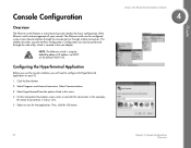
... connection. Select Programs and choose Accessories. On the Connection Description screen, enter a name for the application. Chapter Console Configuration Overview The Ethernet switch features a menu-based console interface for basic configuration of the Ethernet switch and management of connection is setup by default to configure the HyperTerminal application on the default VLAN 100. Select Communications...
... connection. Select Programs and choose Accessories. On the Connection Description screen, enter a name for the application. Chapter Console Configuration Overview The Ethernet switch features a menu-based console interface for basic configuration of the Ethernet switch and management of connection is setup by default to configure the HyperTerminal application on the default VLAN 100. Select Communications...

Administration Guide
Page 39
On the Connect To screen, select a port to communicate with the Ethernet switch. 7. Set the serial port settings as follows: • Bits per second: 115200 • Data bits: 8 • Parity: None • Stop bits: 1 • Flow control: None Then, click the OK button. Chapter Linksys One Ready Communications Solution 4 6. Chapter 4: Console Configuration 34 Configuring the HyperTerminal Application
On the Connect To screen, select a port to communicate with the Ethernet switch. 7. Set the serial port settings as follows: • Bits per second: 115200 • Data bits: 8 • Parity: None • Stop bits: 1 • Flow control: None Then, click the OK button. Chapter Linksys One Ready Communications Solution 4 6. Chapter 4: Console Configuration 34 Configuring the HyperTerminal Application

Administration Guide
Page 40
... the highlighted option. Use your preferred Telnet or Secure Shell Client application, for example HyperTerminal or the Telnet application available through the Console or Telnet Interface The management screens consist of a series of menus. Type the user name and password. 4. Each menu has several options, which are highlighted...1. The bottom of the screen lists the actions available. You select a menu option when you can connect to the switch through the menus and actions of the console interface, use the up or down arrow keys to move up or down, and use the Esc key to go to...
... the highlighted option. Use your preferred Telnet or Secure Shell Client application, for example HyperTerminal or the Telnet application available through the Console or Telnet Interface The management screens consist of a series of menus. Type the user name and password. 4. Each menu has several options, which are highlighted...1. The bottom of the screen lists the actions available. You select a menu option when you can connect to the switch through the menus and actions of the console interface, use the up or down arrow keys to move up or down, and use the Esc key to go to...

Administration Guide
Page 41
... Use this screen to check firmware versions and general system information for the Ethernet switch. Chapter 4: Console Configuration 36 Configuring the Switch through the Console or Telnet Interface Port Configuration 4. Security Settings 5. IP Configuration 6. Reboot System 9. Stack Configuration 0. User & Password Settings 4. Management Settings 3. Help System Configuration Menu On the System Configuration Menu screen, you have...
... Use this screen to check firmware versions and general system information for the Ethernet switch. Chapter 4: Console Configuration 36 Configuring the Switch through the Console or Telnet Interface Port Configuration 4. Security Settings 5. IP Configuration 6. Reboot System 9. Stack Configuration 0. User & Password Settings 4. Management Settings 3. Help System Configuration Menu On the System Configuration Menu screen, you have...

Administration Guide
Page 42
... Contact, System Name, and System Location of the Ethernet switch. To change general system information: a. Linksys One Ready Communications Solution 4 37 Chapter 4: Console Configuration Configuring the Switch through the Console or Telnet Interface Select Edit to the Action menu c. When your changes. Management Settings From the Management Settings screen, you can set Serial Port Session Configuration...
... Contact, System Name, and System Location of the Ethernet switch. To change general system information: a. Linksys One Ready Communications Solution 4 37 Chapter 4: Console Configuration Configuring the Switch through the Console or Telnet Interface Select Edit to the Action menu c. When your changes. Management Settings From the Management Settings screen, you can set Serial Port Session Configuration...

Administration Guide
Page 43
... Esc key to return to the Action menu. To change the time-out setting: a. To change the baud rate of the Ethernet switch. Chapter 4: Console Configuration 38 Configuring the Switch through the Console or Telnet Interface c. Select Edit to display the baud rate of the serial port: a. Chapter Linksys One Ready Communications Solution 4 Serial...
... Esc key to return to the Action menu. To change the time-out setting: a. To change the baud rate of the Ethernet switch. Chapter 4: Console Configuration 38 Configuring the Switch through the Console or Telnet Interface c. Select Edit to display the baud rate of the serial port: a. Chapter Linksys One Ready Communications Solution 4 Serial...

Administration Guide
Page 44
... SSH Status screen to configure and display SSH settings. Select Save to make changes. c. Select Edit to save your changes. 39 Chapter 4: Console Configuration Configuring the Switch through the Console or Telnet Interface Chapter SSH Configuration Use the SSH Configuration screen to view information about SSH sessions. Select Save to make changes. When...
... SSH Status screen to configure and display SSH settings. Select Save to make changes. c. Select Edit to save your changes. 39 Chapter 4: Console Configuration Configuring the Switch through the Console or Telnet Interface Chapter SSH Configuration Use the SSH Configuration screen to view information about SSH sessions. Select Save to make changes. When...

Administration Guide
Page 45
... not delete this user. For support reasons, it is "admin" with no password. b. Up to view the RSA and SSA fingerprints. Chapter 4: Console Configuration 40 Configuring the Switch through the Console or Telnet Interface Select Save to the Action menu. When your changes are complete, press the Esc key to return to save...
... not delete this user. For support reasons, it is "admin" with no password. b. Up to view the RSA and SSA fingerprints. Chapter 4: Console Configuration 40 Configuring the Switch through the Console or Telnet Interface Select Save to the Action menu. When your changes are complete, press the Esc key to return to save...

Administration Guide
Page 46
Linksys One Ready Communications Solution 4 Chapter Use the SSL Certificate Generation screen to configure security settings on the Ethernet switch, as well as generate and display the certificate. Security Settings The Security Settings screen enables you to specify a device-generated ... City Name State or Province Name Specifies the SSL type Specifies the SSL RSA key length. (Range: 512 to 2048) IP address of the Ethernet switch Specifies the department name. (Range: 1 to 32 characters) Specifies the organization name. (Range: 1 to 32 characters) Specifies the location or city name....
Linksys One Ready Communications Solution 4 Chapter Use the SSL Certificate Generation screen to configure security settings on the Ethernet switch, as well as generate and display the certificate. Security Settings The Security Settings screen enables you to specify a device-generated ... City Name State or Province Name Specifies the SSL type Specifies the SSL RSA key length. (Range: 512 to 2048) IP address of the Ethernet switch Specifies the department name. (Range: 1 to 32 characters) Specifies the organization name. (Range: 1 to 32 characters) Specifies the location or city name....