Getting Started Guide
Page 1
GETTING STARTED GUIDE Cisco 2500 Series Wireless Controller May 2011 Revised June 2, 2011 1 About This Guide 2 Unpacking and Preparing the Controller for Operation 3 Installing the Controller 4 Running the Bootup Script and Power-On Self Test 5 Logging into the Controller 6 Connecting to the Network 7 What's New in Cisco Product Documentation 8 Translated Safety Warnings
GETTING STARTED GUIDE Cisco 2500 Series Wireless Controller May 2011 Revised June 2, 2011 1 About This Guide 2 Unpacking and Preparing the Controller for Operation 3 Installing the Controller 4 Running the Bootup Script and Power-On Self Test 5 Logging into the Controller 6 Connecting to the Network 7 What's New in Cisco Product Documentation 8 Translated Safety Warnings
Getting Started Guide
Page 2
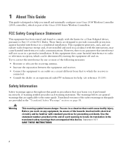
... warnings that are applicable to the entire guide. However, there is no guarantee that could cause bodily injury. Translated versions of the Cisco 2500 Series Wireless Controllers. Before you work on . 1 About This Guide This guide is designed to help . (cfr reference 15...general warnings that accompanied this equipment does cause harmful interference to comply with the instructions, may harm you install and minimally configure your Cisco 2504 Wireless Controller (2504 controller), which the receiver is connected. • Consult the dealer or an experienced radio/TV technician ...
... warnings that are applicable to the entire guide. However, there is no guarantee that could cause bodily injury. Translated versions of the Cisco 2500 Series Wireless Controllers. Before you work on . 1 About This Guide This guide is designed to help . (cfr reference 15...general warnings that accompanied this equipment does cause harmful interference to comply with the instructions, may harm you install and minimally configure your Cisco 2504 Wireless Controller (2504 controller), which the receiver is connected. • Consult the dealer or an experienced radio/TV technician ...
Getting Started Guide
Page 3
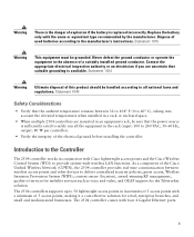
...a suitably installed ground conductor. The 2504 controllers supports up to the manufacturer's instructions. The 2504 controller comes with Cisco lightweight access points and the Cisco Wireless Control System (WCS) to the Controller The 2504 controller works in the rack (input: 100 to deliver ... equipment rack, be handled according to all the equipment in conjunction with four 4 Gigabit Ethernet ports. 3 As a component of the Cisco Unified Wireless Network (CUWN), the 2504 controller provides real-time communication between 32 to 104° F (0 to safely run all national...
...a suitably installed ground conductor. The 2504 controllers supports up to the manufacturer's instructions. The 2504 controller comes with Cisco lightweight access points and the Cisco Wireless Control System (WCS) to the Controller The 2504 controller works in the rack (input: 100 to deliver ... equipment rack, be handled according to all the equipment in conjunction with four 4 Gigabit Ethernet ports. 3 As a component of the Cisco Unified Wireless Network (CUWN), the 2504 controller provides real-time communication between 32 to 104° F (0 to safely run all national...
Getting Started Guide
Page 4
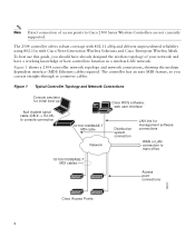
... points to main office 10/100/1000BASE-T MDI cables Access point connections 282297 Cisco Access Points 4 Figure 1 Typical Controller Topology and Network Connections Console emulator for initial boot-up Null modem serial cable (DB-9 -> RJ-45) to console connection Cisco WCS software, web user interface 10/100/1000BASE-T MDI cable Network Distribution system...
... points to main office 10/100/1000BASE-T MDI cables Access point connections 282297 Cisco Access Points 4 Figure 1 Typical Controller Topology and Network Connections Console emulator for initial boot-up Null modem serial cable (DB-9 -> RJ-45) to console connection Cisco WCS software, web user interface 10/100/1000BASE-T MDI cable Network Distribution system...
Getting Started Guide
Page 5
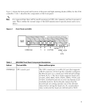
... the baud rate will be small variations in LED color intensity and hue from unit to 9600. 5 Figure 2 Front Panel and LEDs 282249 CONSOLE CONSOLE CISCO 2500 Series WIRELESS CONTROLLER RESET Model 2504 1 2 3 4 PWR SYS ALM RESET 1 2 3-4 POE PWR ALM SYS Table 1 Callout WLC2504 Front Panel Component Descriptions Port and LEDs...
... the baud rate will be small variations in LED color intensity and hue from unit to 9600. 5 Figure 2 Front Panel and LEDs 282249 CONSOLE CONSOLE CISCO 2500 Series WIRELESS CONTROLLER RESET Model 2504 1 2 3 4 PWR SYS ALM RESET 1 2 3-4 POE PWR ALM SYS Table 1 Callout WLC2504 Front Panel Component Descriptions Port and LEDs...

Getting Started Guide
Page 6
LED description: • Green or Blinking Green-Link activity • Off-No link 2 GigE port and LED The Gigabit Ethernet port is driven from system reset. They provide a I2C communications channel between chassis ground and any 48V/Ethernet signal. If software needs to reset the POE controller, it can be used for infra-switch connection using multiple an AP-Manager or data interface. 6 This interface supports the proper voltage isolation as defined by 802.3. This port is designed so that 1500 VAC rms isolation (per the 802.3 specification) is met between chassis...
LED description: • Green or Blinking Green-Link activity • Off-No link 2 GigE port and LED The Gigabit Ethernet port is driven from system reset. They provide a I2C communications channel between chassis ground and any 48V/Ethernet signal. If software needs to reset the POE controller, it can be used for infra-switch connection using multiple an AP-Manager or data interface. 6 This interface supports the proper voltage isolation as defined by 802.3. This port is designed so that 1500 VAC rms isolation (per the 802.3 specification) is met between chassis...
Getting Started Guide
Page 7
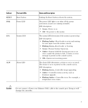
Callout RESET PWR Port and LEDs Reset button Power LED SYS System LED ALM Alarm LED State and Description Pushing the Reset button reboots the system. LED description: • Blinking Green-Controller image upgrading. • Amber-Controller status activity, such as firmware upgrade. • Blinking Amber-Controller error. The alarm LED determines a status or error occurred. For example, a temperature error exists. The status or error is posted on the console screen. A status or error message is posted on the console screen. • Off-System not receiving power. ...
Callout RESET PWR Port and LEDs Reset button Power LED SYS System LED ALM Alarm LED State and Description Pushing the Reset button reboots the system. LED description: • Blinking Green-Controller image upgrading. • Amber-Controller status activity, such as firmware upgrade. • Blinking Amber-Controller error. The alarm LED determines a status or error occurred. For example, a temperature error exists. The status or error is posted on the console screen. A status or error message is posted on the console screen. • Off-System not receiving power. ...
Getting Started Guide
Page 8
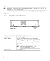
... State and Description The 48 V input power is enough power available to the system board from the 48 VDC input. Cable Lock slot Note The Cisco 2106 power adapter is provided to power the system board plus two 802.3af PoE devices. Otherwise, the controller may fail to the controller. Power...
... State and Description The 48 V input power is enough power available to the system board from the 48 VDC input. Cable Lock slot Note The Cisco 2106 power adapter is provided to power the system board plus two 802.3af PoE devices. Otherwise, the controller may fail to the controller. Power...
Getting Started Guide
Page 9
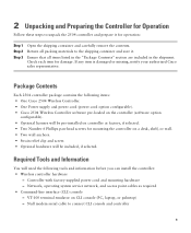
... operating system service network, and access point cables as required • Command-line interface (CLI) console - Null modem serial cable to unpack the 2504 controller and prepare it . 2 Unpacking and Preparing the Controller for Operation Follow these steps to... container and carefully remove the contents. If any item is damaged or missing, notify your authorized Cisco sales representative. Package Contents Each 2504 controller package contains the following items: • One Cisco 2504 Wireless Controller. • One Power supply and power cord (power cord option configurable). &#...
... operating system service network, and access point cables as required • Command-line interface (CLI) console - Null modem serial cable to unpack the 2504 controller and prepare it . 2 Unpacking and Preparing the Controller for Operation Follow these steps to... container and carefully remove the contents. If any item is damaged or missing, notify your authorized Cisco sales representative. Package Contents Each 2504 controller package contains the following items: • One Cisco 2504 Wireless Controller. • One Power supply and power cord (power cord option configurable). &#...

Getting Started Guide
Page 10
... wlan1. Yes is assigned to 19 printable ASCII characters. • An 802.11 network name (SSID), such as the Cisco WCS because Cisco WCS and third-party TFTP servers use the same communication port. Initial System Configuration Information Obtain the following initial configuration parameters from... address, such as 10.40.0.4. • A management interface netmask address, such as 255.255.255.0. • A management interface default router IP address, such as rfgrp40 if required. No is less convenient, but has lower security (session can contain up to clients and the management...
... wlan1. Yes is assigned to 19 printable ASCII characters. • An 802.11 network name (SSID), such as the Cisco WCS because Cisco WCS and third-party TFTP servers use the same communication port. Initial System Configuration Information Obtain the following initial configuration parameters from... address, such as 10.40.0.4. • A management interface netmask address, such as 255.255.255.0. • A management interface default router IP address, such as rfgrp40 if required. No is less convenient, but has lower security (session can contain up to clients and the management...

Getting Started Guide
Page 11
Enter help to see a list or refer to the Cisco Wireless LAN Controller Configuration Guide for this installation. This guide is not obstructed. Choosing a Physical Location You can install the controller almost anywhere, but it ...: • Make sure you are configuring a RADIUS server, such as 10.40.0.3, 1812, and mysecretcode. • The country code for country code information. Leave at cisco.com. • Status of the 802.11a, 802.11b, 802.11g, or 802.11n networks, either enabled or disabled.
Enter help to see a list or refer to the Cisco Wireless LAN Controller Configuration Guide for this installation. This guide is not obstructed. Choosing a Physical Location You can install the controller almost anywhere, but it ...: • Make sure you are configuring a RADIUS server, such as 10.40.0.3, 1812, and mysecretcode. • The country code for country code information. Leave at cisco.com. • Status of the 802.11a, 802.11b, 802.11g, or 802.11n networks, either enabled or disabled.

Getting Started Guide
Page 12
Doing so helps prevent airflow restriction and overheating. Figure 4 Installing the Rubber Feet on the Bottom of the unit as shown in the mounting-kit envelope. Note We strongly recommend that you attach the rubber feet. • Mounting the Controller on a Wall (Rack-Mount Brackets) • Mounting the Controller on a Wall (Mounting Screws) • Mounting the Controller in a Rack Mounting the Controller on a Desktop or Shelf Before mounting the controller on a desktop or shelf, install the rubber feet located in accessory kit shipped with the rubber feet in Figure 4. To ...
Doing so helps prevent airflow restriction and overheating. Figure 4 Installing the Rubber Feet on the Bottom of the unit as shown in the mounting-kit envelope. Note We strongly recommend that you attach the rubber feet. • Mounting the Controller on a Wall (Rack-Mount Brackets) • Mounting the Controller on a Wall (Mounting Screws) • Mounting the Controller in a Rack Mounting the Controller on a Desktop or Shelf Before mounting the controller on a desktop or shelf, install the rubber feet located in accessory kit shipped with the rubber feet in Figure 4. To ...

Getting Started Guide
Page 13
... on page 23. Mounting the Controller on a Wall (Rack-Mount Brackets) The controller can order a kit with 19-inch rack mounting brackets and hardware from Cisco. The kit part number is AIR-CT2504-RMNT. Warning Read the wall-mounting carefully before beginning installation. Step 3 Place the switch on a wall using rack...
... on page 23. Mounting the Controller on a Wall (Rack-Mount Brackets) The controller can order a kit with 19-inch rack mounting brackets and hardware from Cisco. The kit part number is AIR-CT2504-RMNT. Warning Read the wall-mounting carefully before beginning installation. Step 3 Place the switch on a wall using rack...

Getting Started Guide
Page 14
For the best support of the controller) Step 2 Mount the 2504 controller on the wall with the front panel facing down, as shown Figure 6. Figure 5 Installing the Rack-Mount Brackets to the Sides of the Controller 1 282083 BASE MOUNT 1 1 #10-32 flat head screws (mounting screws for each side of the controller and cables, make sure the controller is attached securely to wall studs or to a firmly attached plywood mounting backboard. 14
For the best support of the controller) Step 2 Mount the 2504 controller on the wall with the front panel facing down, as shown Figure 6. Figure 5 Installing the Rack-Mount Brackets to the Sides of the Controller 1 282083 BASE MOUNT 1 1 #10-32 flat head screws (mounting screws for each side of the controller and cables, make sure the controller is attached securely to wall studs or to a firmly attached plywood mounting backboard. 14

Getting Started Guide
Page 15
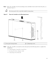
Figure 6 Mounting the Controller on page 23. Mounting the Controller on a Wall (Mounting Screws) When mounting the 2504 controller on a wall using mounting screws, always mount the controller with the front panel facing down ) 2 #10-32 flat head screws 3 Wall mounting screws Step 3 Step 4 After the controller is mounted on the wall, perform the following tasks to complete the installation: • Connecting the Controller Console Port • Securing the Power Adapter Cable • Connecting to the Network For configuration instructions about using the CLI setup program, see the "...
Figure 6 Mounting the Controller on page 23. Mounting the Controller on a Wall (Mounting Screws) When mounting the 2504 controller on a wall using mounting screws, always mount the controller with the front panel facing down ) 2 #10-32 flat head screws 3 Wall mounting screws Step 3 Step 4 After the controller is mounted on the wall, perform the following tasks to complete the installation: • Connecting the Controller Console Port • Securing the Power Adapter Cable • Connecting to the Network For configuration instructions about using the CLI setup program, see the "...

Getting Started Guide
Page 16
Warning Read the wall-mounting carefully before beginning installation. Use the mount hole locations on the back of the controller for placement of the mounting screws (Figure 7). (The mount holes are 1/8 inch from the wall (leaving enough room for the two mounting screws. Failure to use the correct hardware or to follow these steps: Step 1 Mark the location of the mounting screws on the Back of the screws are shown in a hazardous situation to people and damage to drill a 3/4 inch (19mm) hole for the back panel to slide onto the screws firmly). 16 Insert two screws into the ...
Warning Read the wall-mounting carefully before beginning installation. Use the mount hole locations on the back of the controller for placement of the mounting screws (Figure 7). (The mount holes are 1/8 inch from the wall (leaving enough room for the two mounting screws. Failure to use the correct hardware or to follow these steps: Step 1 Mark the location of the mounting screws on the Back of the screws are shown in a hazardous situation to people and damage to drill a 3/4 inch (19mm) hole for the back panel to slide onto the screws firmly). 16 Insert two screws into the ...
Getting Started Guide
Page 17
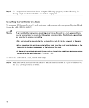
Step 4 Place the controller onto the mounting screws and slide it down . Note The front panel of the controller should be facing down until it lock into place, as shown in Figure 8. Figure 8 Place the Controller on the Mounting Screws 282085 2 1 2 1 Front panel (facing down) 2 Mounting screws Step 5 After the controller is mounted ion the wall, perform the following tasks to complete the installation: • Connecting the Controller Console Port • Securing the Power Adapter Cable • Connecting to the Network 17
Step 4 Place the controller onto the mounting screws and slide it down . Note The front panel of the controller should be facing down until it lock into place, as shown in Figure 8. Figure 8 Place the Controller on the Mounting Screws 282085 2 1 2 1 Front panel (facing down) 2 Mounting screws Step 5 After the controller is mounted ion the wall, perform the following tasks to complete the installation: • Connecting the Controller Console Port • Securing the Power Adapter Cable • Connecting to the Network 17
Getting Started Guide
Page 18
The following guidelines are provided to ensure your safety: • This unit should be mounted at the bottom of the controller as shown in Figure 9 with stabilizing devices, install the stabilizers before mounting or servicing the unit in the rack. Step 1 Attach the 19-inch brackets to the top with the heaviest component at the bottom of the rack if it is the only unit in the rack. • When mounting this unit in a 19-inch equipment rack, you must take special precautions to ensure that the system remains stable. Warning To prevent bodily injury when mounting or servicing this...
The following guidelines are provided to ensure your safety: • This unit should be mounted at the bottom of the controller as shown in Figure 9 with stabilizing devices, install the stabilizers before mounting or servicing the unit in the rack. Step 1 Attach the 19-inch brackets to the top with the heaviest component at the bottom of the rack if it is the only unit in the rack. • When mounting this unit in a 19-inch equipment rack, you must take special precautions to ensure that the system remains stable. Warning To prevent bodily injury when mounting or servicing this...

Getting Started Guide
Page 19
Use either the 10-32 pan-head screws or the 12-24 slotted head screws to the sides of the controller, insert the controller into the 19-inch rack. 282082 Figure 9 Attaching the 19-Inch Brackets to the Side of the Controller. 1 RACK MOUNT 1 1 #10-32 flat head screws (mounting screws for each side of the controller) Step 2 After the brackets are attached to secure the controller in the rack, as shown in Figure 10. 19
Use either the 10-32 pan-head screws or the 12-24 slotted head screws to the sides of the controller, insert the controller into the 19-inch rack. 282082 Figure 9 Attaching the 19-Inch Brackets to the Side of the Controller. 1 RACK MOUNT 1 1 #10-32 flat head screws (mounting screws for each side of the controller) Step 2 After the brackets are attached to secure the controller in the rack, as shown in Figure 10. 19

Getting Started Guide
Page 20
Figure 10 Mounting the Controller in a 19-Inch Rack 1 282086 1 #10-32 pan-head screws or #12-24 slotted head screws Step 3 Step 4 After the controller is mounted in the rack, perform the following tasks to complete the installation: • Connecting the Controller Console Port • Securing the Power Adapter Cable • Connecting to the Network For configuration instructions about using the CLI setup program, see the "Running the Bootup Script and Power-On Self Test" section on page 23. 20
Figure 10 Mounting the Controller in a 19-Inch Rack 1 282086 1 #10-32 pan-head screws or #12-24 slotted head screws Step 3 Step 4 After the controller is mounted in the rack, perform the following tasks to complete the installation: • Connecting the Controller Console Port • Securing the Power Adapter Cable • Connecting to the Network For configuration instructions about using the CLI setup program, see the "Running the Bootup Script and Power-On Self Test" section on page 23. 20