
User Guide
Page 1
... the most: Document Information Document Title: Catalyst 8540 Chassis Installation Guide Part Number: 78-6134-03 On a scale of understanding. The document was complete. Cisco Reader Comment Card General Information 1 Years of networking experience Years of experience with Cisco products 2 I have these network types: Other: LAN Backbone WAN 3 I have these Cisco products: Other: Specify model(s) Switches Routers 4 I perform these types of tasks: Network Management H/W Install and/or Maintenance Other: S/W Config 5 I use the following areas: The document was written at...
... the most: Document Information Document Title: Catalyst 8540 Chassis Installation Guide Part Number: 78-6134-03 On a scale of understanding. The document was complete. Cisco Reader Comment Card General Information 1 Years of networking experience Years of experience with Cisco products 2 I have these network types: Other: LAN Backbone WAN 3 I have these Cisco products: Other: Specify model(s) Switches Routers 4 I perform these types of tasks: Network Management H/W Install and/or Maintenance Other: S/W Config 5 I use the following areas: The document was written at...

User Guide
Page 4
.... THE SOFTWARE LICENSE AND LIMITED WARRANTY FOR THE ACCOMPANYING PRODUCT ARE SET FORTH IN THE INFORMATION PACKET THAT SHIPPED WITH THE PRODUCT AND ARE INCORPORATED HEREIN BY THIS REFERENCE. This equipment has been tested and found to part 15 of...Cisco's installation instructions, it was probably caused by using one of a program developed by Cisco Systems, Inc. NOTWITHSTANDING ANY OTHER WARRANTY HEREIN, ALL DOCUMENT FILES AND SOFTWARE OF THESE SUPPLIERS ARE PROVIDED "AS IS" WITH ALL FAULTS. THE SPECIFICATIONS AND INFORMATION REGARDING THE PRODUCTS IN THIS MANUAL ARE SUBJECT TO CHANGE...
.... THE SOFTWARE LICENSE AND LIMITED WARRANTY FOR THE ACCOMPANYING PRODUCT ARE SET FORTH IN THE INFORMATION PACKET THAT SHIPPED WITH THE PRODUCT AND ARE INCORPORATED HEREIN BY THIS REFERENCE. This equipment has been tested and found to part 15 of...Cisco's installation instructions, it was probably caused by using one of a program developed by Cisco Systems, Inc. NOTWITHSTANDING ANY OTHER WARRANTY HEREIN, ALL DOCUMENT FILES AND SOFTWARE OF THESE SUPPLIERS ARE PROVIDED "AS IS" WITH ALL FAULTS. THE SPECIFICATIONS AND INFORMATION REGARDING THE PRODUCTS IN THIS MANUAL ARE SUBJECT TO CHANGE...
User Guide
Page 5
..., MICA, NetRanger, Post-Routing, Pre-Routing, Registrar, StrataView Plus, Stratm, TeleRouter, and VCO are service marks; or its resellers. (9912R) Catalyst 8540 Chassis Installation Guide Copyright © 1998-2000, Cisco Systems, Inc. All rights reserved. and certain other trademarks mentioned in this document are trademarks; Changing the Way We Work, Live, Play, and Learn, Empowering the Internet Generation, The Internet Economy, and The New...
..., MICA, NetRanger, Post-Routing, Pre-Routing, Registrar, StrataView Plus, Stratm, TeleRouter, and VCO are service marks; or its resellers. (9912R) Catalyst 8540 Chassis Installation Guide Copyright © 1998-2000, Cisco Systems, Inc. All rights reserved. and certain other trademarks mentioned in this document are trademarks; Changing the Way We Work, Live, Play, and Learn, Empowering the Internet Generation, The Internet Economy, and The New...
User Guide
Page 7
1 C H A P T E R Preface vii Audience vii New and Changed Information vii Organization viii Conventions viii Related Documentation xi Obtaining Documentation xiii World Wide Web xiii Documentation CD-ROM xiii Ordering Documentation xiv Obtaining Technical Assistance xiv Cisco Connection Online xiv Technical Assistance Center xv Documentation Feedback xvi Product Overview 1-1 Interface Modules and Port Adapters 1-2 Route Processors 1-3 Switch Modules 1-3 Power Supplies 1-4 Fan Assembly 1-5 CONTENTS 78-6134-03 Catalyst 8540 Chassis Installation Guide v
1 C H A P T E R Preface vii Audience vii New and Changed Information vii Organization viii Conventions viii Related Documentation xi Obtaining Documentation xiii World Wide Web xiii Documentation CD-ROM xiii Ordering Documentation xiv Obtaining Technical Assistance xiv Cisco Connection Online xiv Technical Assistance Center xv Documentation Feedback xvi Product Overview 1-1 Interface Modules and Port Adapters 1-2 Route Processors 1-3 Switch Modules 1-3 Power Supplies 1-4 Fan Assembly 1-5 CONTENTS 78-6134-03 Catalyst 8540 Chassis Installation Guide v
User Guide
Page 15
... and Safety Guide • Catalyst 8540 Hardware Quick Reference • Cisco Interactive Quick Start Guides: Catalyst 8540 http://www.cisco.com/mm/quickstart/ • Processor Installation Guide • ATM Port Adapter and Interface Module Installation Guide • Guide to ATM Technology • ATM Switch Router Quick Software Configuration Guide • ATM Switch Router Software Configuration Guide • ATM Switch Router Command Reference • ATM Switch Router Troubleshooting Guide Obtaining Documentation World Wide Web You can access the most current Cisco documentation on the...
... and Safety Guide • Catalyst 8540 Hardware Quick Reference • Cisco Interactive Quick Start Guides: Catalyst 8540 http://www.cisco.com/mm/quickstart/ • Processor Installation Guide • ATM Port Adapter and Interface Module Installation Guide • Guide to ATM Technology • ATM Switch Router Quick Software Configuration Guide • ATM Switch Router Software Configuration Guide • ATM Switch Router Command Reference • ATM Switch Router Troubleshooting Guide Obtaining Documentation World Wide Web You can access the most current Cisco documentation on the...

User Guide
Page 16
..., in the world. Catalyst 8540 Chassis Installation Guide xiv 78-6134-03 CCO's broad range of an order and view benefits specific to Cisco. Obtaining Technical Assistance Preface Ordering Documentation Registered CCO users can order the Documentation CD-ROM and other Cisco Product documentation through a local account representative by sending mail to their relationships with online support services, download and test software packages, and order Cisco learning materials and merchandise...
..., in the world. Catalyst 8540 Chassis Installation Guide xiv 78-6134-03 CCO's broad range of an order and view benefits specific to Cisco. Obtaining Technical Assistance Preface Ordering Documentation Registered CCO users can order the Documentation CD-ROM and other Cisco Product documentation through a local account representative by sending mail to their relationships with online support services, download and test software packages, and order Cisco learning materials and merchandise...

User Guide
Page 17
... about using standard connection rates and the following web site: http://www.cisco.com/warp/public/687/Directory/DirTAC.shtml. 78-6134-03 Catalyst 8540 Chassis Installation Guide xv To contact by a maintenance contract. From Europe, call 408 526-8070 - Technical Assistance Center The Cisco Technical Assistance Center (TAC) is available to cco-team@cisco.com. For other telephone numbers and TAC e-mail addresses...
... about using standard connection rates and the following web site: http://www.cisco.com/warp/public/687/Directory/DirTAC.shtml. 78-6134-03 Catalyst 8540 Chassis Installation Guide xv To contact by a maintenance contract. From Europe, call 408 526-8070 - Technical Assistance Center The Cisco Technical Assistance Center (TAC) is available to cco-team@cisco.com. For other telephone numbers and TAC e-mail addresses...

User Guide
Page 18
... can e-mail your comments to the following address: Cisco Systems, Inc. Catalyst 8540 Chassis Installation Guide xvi 78-6134-03 To submit your comments by mail, for your comments. Click Feedback in the toolbar and select Documentation. Obtaining Technical Assistance Preface Documentation Feedback If you are reading Cisco product documentation on the World Wide Web, you complete the form, click Submit to...
... can e-mail your comments to the following address: Cisco Systems, Inc. Catalyst 8540 Chassis Installation Guide xvi 78-6134-03 To submit your comments by mail, for your comments. Click Feedback in the toolbar and select Documentation. Obtaining Technical Assistance Preface Documentation Feedback If you are reading Cisco product documentation on the World Wide Web, you complete the form, click Submit to...
User Guide
Page 19
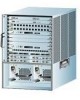
... 8540 CSR hardware components and installation. The following sections describe the chassis components: • Interface Modules and Port Adapters • Route Processors • Switch Modules • Power Supplies • Fan Assembly The chassis ships populated specifically to the Processor Installation Guide and the ATM Port Adapter and Interface Module Installation Guide for detailed information about the Catalyst 8540 MSR hardware components and installation. 78-6134-03 Catalyst 8540 Chassis Installation Guide 1-1 Figure 1-1 shows an example of the chassis components. Refer...
... 8540 CSR hardware components and installation. The following sections describe the chassis components: • Interface Modules and Port Adapters • Route Processors • Switch Modules • Power Supplies • Fan Assembly The chassis ships populated specifically to the Processor Installation Guide and the ATM Port Adapter and Interface Module Installation Guide for detailed information about the Catalyst 8540 MSR hardware components and installation. 78-6134-03 Catalyst 8540 Chassis Installation Guide 1-1 Figure 1-1 shows an example of the chassis components. Refer...

User Guide
Page 20
... can install up to network services. Slots 4 and 8 are reserved for switch modules. Catalyst 8540 Chassis Installation Guide 1-2 78-6134-03 Interface Modules and Port Adapters Figure 1-1 Catalyst 8540 Chassis Slots 0-3: Interface modules Slot 4: Route processor Slots 5-7: Switch modules Slot 8: Redundant route processor Slots 9-12: Interface modules Chapter 1 Product Overview 32600 INPUT FAN OUTPUT OK OK FAIL INPUT FAN OK OK Power supply 0 Power supply 1 Interface Modules and Port Adapters The Catalyst 8540 interface modules and port adapters provide ports for connection to...
... can install up to network services. Slots 4 and 8 are reserved for switch modules. Catalyst 8540 Chassis Installation Guide 1-2 78-6134-03 Interface Modules and Port Adapters Figure 1-1 Catalyst 8540 Chassis Slots 0-3: Interface modules Slot 4: Route processor Slots 5-7: Switch modules Slot 8: Redundant route processor Slots 9-12: Interface modules Chapter 1 Product Overview 32600 INPUT FAN OUTPUT OK OK FAIL INPUT FAN OK OK Power supply 0 Power supply 1 Interface Modules and Port Adapters The Catalyst 8540 interface modules and port adapters provide ports for connection to...
User Guide
Page 21
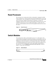
... chassis. The third switch module provides redundancy for operation. By default, switch modules 5 and 7 are required for only one of the two active modules in the event that you remove one of the system memory components and the main system processor, which maintains and executes the management functions that control the chassis. Figure 1-3 Switch Module STATUS ASCTATNIVDEBY SWITCH PROCESSOR 32602 78-6134-03 Catalyst 8540 Chassis Installation Guide 1-3 This redundant route...
... chassis. The third switch module provides redundancy for operation. By default, switch modules 5 and 7 are required for only one of the two active modules in the event that you remove one of the system memory components and the main system processor, which maintains and executes the management functions that control the chassis. Figure 1-3 Switch Module STATUS ASCTATNIVDEBY SWITCH PROCESSOR 32602 78-6134-03 Catalyst 8540 Chassis Installation Guide 1-3 This redundant route...
User Guide
Page 22
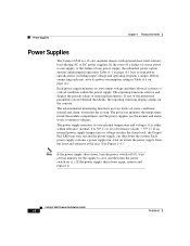
... use the normal and alarm levels to cool, and then turn red and the power supply can shut down again, remove and replace it detects a critical condition within tolerance (normal, 0 to 50° C) or out of the monitored parameters exceed defined thresholds, the reporting functions display alarms on page A-1. The power supply monitors its power consumption rating in Table A-1 on the console. Catalyst 8540 Chassis Installation Guide...
... use the normal and alarm levels to cool, and then turn red and the power supply can shut down again, remove and replace it detects a critical condition within tolerance (normal, 0 to 50° C) or out of the monitored parameters exceed defined thresholds, the reporting functions display alarms on page A-1. The power supply monitors its power consumption rating in Table A-1 on the console. Catalyst 8540 Chassis Installation Guide...
User Guide
Page 25
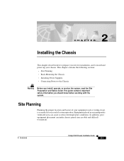
...; Site Planning • Rack-Mounting the Chassis • Installing Power Supplies • Connecting Power to maintain. 78-6134-03 Catalyst 8540 Chassis Installation Guide 2-1 In addition, poor equipment placement can cause system overtemperature conditions. Equipment placed in an inadequately ventilated area can make chassis panels inaccessible and difficult to the Chassis Warning Before you should know before working with the system. CH A P T E R 2 Installing the Chassis This chapter describes how...
...; Site Planning • Rack-Mounting the Chassis • Installing Power Supplies • Connecting Power to maintain. 78-6134-03 Catalyst 8540 Chassis Installation Guide 2-1 In addition, poor equipment placement can cause system overtemperature conditions. Equipment placed in an inadequately ventilated area can make chassis panels inaccessible and difficult to the Chassis Warning Before you should know before working with the system. CH A P T E R 2 Installing the Chassis This chapter describes how...
User Guide
Page 26
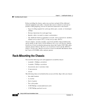
Rack-Mounting the Chassis Chapter 2 Installing the Chassis Before installing the chassis, make sure you need, such as transceivers, modems, channel service units (CSUs), or data service units (DSUs) All port adapters, interface modules, and switch modules ship installed in the accessory kit that ships with your site for network connections to the chassis: • Type of cabling required for each type (fiber-optic, coaxial, or twisted-pair cabling) • Distance limitations for each signal type • Specific cables you need...
Rack-Mounting the Chassis Chapter 2 Installing the Chassis Before installing the chassis, make sure you need, such as transceivers, modems, channel service units (CSUs), or data service units (DSUs) All port adapters, interface modules, and switch modules ship installed in the accessory kit that ships with your site for network connections to the chassis: • Type of cabling required for each type (fiber-optic, coaxial, or twisted-pair cabling) • Distance limitations for each signal type • Specific cables you need...
User Guide
Page 39
... and interface modules. This guide contains important safety information you should know before working with the system. Your chassis is configured as power supplies and system fan assemblies for detailed information about the maintenance of the Catalyst 8540 MSR route processors, port adapters, and interface modules. 78-6134-03 Catalyst 8540 Chassis Installation Guide 3-1 Refer to the Processor Installation Guide and the ATM Port Adapter and Interface Module Installation Guide for the chassis. CH A P T E R 3 Maintaining the Chassis This chapter describes how to replace...
... and interface modules. This guide contains important safety information you should know before working with the system. Your chassis is configured as power supplies and system fan assemblies for detailed information about the maintenance of the Catalyst 8540 MSR route processors, port adapters, and interface modules. 78-6134-03 Catalyst 8540 Chassis Installation Guide 3-1 Refer to the Processor Installation Guide and the ATM Port Adapter and Interface Module Installation Guide for the chassis. CH A P T E R 3 Maintaining the Chassis This chapter describes how to replace...
User Guide
Page 49
... x 48.2 cm) Chassis depth including cable guide: 21.64 in. (55.0 cm) Power supply: 7.1 x 7.9 x 15.3 in Table A-1. A A P P E N D I X Chassis and Power Supply Specifications The chassis and power supply specifications are described in . (20.1 x 18.1 x 38.9 cm) Weight Airflow Chassis only: 70 lb (31.7 kg) Chassis fully configured with 2 route processors, 8 line modules, 3 switch modules, and 2 power supplies:160 lb (72.5 kg) AC power supply: 22 lb DC power supply: 25 lb 200 lfm1 through the system fan assembly Operating temperature...
... x 48.2 cm) Chassis depth including cable guide: 21.64 in. (55.0 cm) Power supply: 7.1 x 7.9 x 15.3 in Table A-1. A A P P E N D I X Chassis and Power Supply Specifications The chassis and power supply specifications are described in . (20.1 x 18.1 x 38.9 cm) Weight Airflow Chassis only: 70 lb (31.7 kg) Chassis fully configured with 2 route processors, 8 line modules, 3 switch modules, and 2 power supplies:160 lb (72.5 kg) AC power supply: 22 lb DC power supply: 25 lb 200 lfm1 through the system fan assembly Operating temperature...

User Guide
Page 50
... Hz with UTP13 cables EN 55022 Class B; CISPR22 Class B, AS/NZS 3548 Class B, and VCCI Class B with FTP14 cables AC Power Supply Specifications AC total output 1300W maximum AC voltage 100 to 240 VAC wide input with power factor correction Power supply load 1300W maximum configuration, 1000W typical with maximum configuration AC current Heat dissipation Rated 16 to 60 Hz Catalyst 8540 Chassis Installation Guide A-2 78-6134...
... Hz with UTP13 cables EN 55022 Class B; CISPR22 Class B, AS/NZS 3548 Class B, and VCCI Class B with FTP14 cables AC Power Supply Specifications AC total output 1300W maximum AC voltage 100 to 240 VAC wide input with power factor correction Power supply load 1300W maximum configuration, 1000W typical with maximum configuration AC current Heat dissipation Rated 16 to 60 Hz Catalyst 8540 Chassis Installation Guide A-2 78-6134...

User Guide
Page 51
...Commission. 6. LightStream 1010 port adapters installed in a Catalyst 8540 MSR chassis may not be EMI compliant. FCC = Federal Communications Commission. 78-6134-03 Catalyst 8540 Chassis Installation Guide A-3 Appendix A Chassis and Power Supply Specifications Table A-1 Chassis and Power Supply Specifications (continued) Description Specifications DC Power Supply Specifications DC total output 1360W maximum DC voltage Typical range (U.S. AS/NZS = Australian/New Zealand Standard. 8. An EMI strip ships with the chassis for installation on the port adapters to -60 VDC continuous...
...Commission. 6. LightStream 1010 port adapters installed in a Catalyst 8540 MSR chassis may not be EMI compliant. FCC = Federal Communications Commission. 78-6134-03 Catalyst 8540 Chassis Installation Guide A-3 Appendix A Chassis and Power Supply Specifications Table A-1 Chassis and Power Supply Specifications (continued) Description Specifications DC Power Supply Specifications DC total output 1360W maximum DC voltage Typical range (U.S. AS/NZS = Australian/New Zealand Standard. 8. An EMI strip ships with the chassis for installation on the port adapters to -60 VDC continuous...
User Guide
Page 53
... belangrijke beveiligingsvoorschriften waarvan u op de hoogte moet zijn voordat u met het systeem gaat werken. 78-6134-03 Catalyst 8540 Chassis Installation Guide B-1 APPENDIX B Translated Safety Warnings This appendix repeats the warnings in this guide in the Regulatory Compliance and Safety Information for the Catalyst 8500 and LightStream 1010 Series document. Note Additional translated safety warnings can be found in...
... belangrijke beveiligingsvoorschriften waarvan u op de hoogte moet zijn voordat u met het systeem gaat werken. 78-6134-03 Catalyst 8540 Chassis Installation Guide B-1 APPENDIX B Translated Safety Warnings This appendix repeats the warnings in this guide in the Regulatory Compliance and Safety Information for the Catalyst 8500 and LightStream 1010 Series document. Note Additional translated safety warnings can be found in...
User Guide
Page 62
Index redundancy preferred-switch-card slots command 1-3 removing components AC power supply 3-2 DC power supply 3-5 fan assembly 3-6 power supplies 2-7 route processors description 1-3 redundancy 1-3 related documentation 1-1 slots 1-3 S safety preinstall 2-1, 3-1 warnings B-1 site environment layout 2-1 preparing 2-1 specifications AC power supply A-2 airflow A-1 chassis A-1 DC power supply A-3 switch modules description 1-3 redundancy 1-3 related documentation 1-1 Catalyst 8540 Chassis Installation Guide 4 slots 1-3 T TAC contacts xv description xiv, xv obtaining xiv, xv Technical ...
Index redundancy preferred-switch-card slots command 1-3 removing components AC power supply 3-2 DC power supply 3-5 fan assembly 3-6 power supplies 2-7 route processors description 1-3 redundancy 1-3 related documentation 1-1 slots 1-3 S safety preinstall 2-1, 3-1 warnings B-1 site environment layout 2-1 preparing 2-1 specifications AC power supply A-2 airflow A-1 chassis A-1 DC power supply A-3 switch modules description 1-3 redundancy 1-3 related documentation 1-1 Catalyst 8540 Chassis Installation Guide 4 slots 1-3 T TAC contacts xv description xiv, xv obtaining xiv, xv Technical ...


