
Hardware Installation Guide
Page 7
... Connecting to an LRE Port 2-38 Connecting to a Module Port 2-42 Connecting to the Console Port 2-42 Where to Go Next 2-43 Troubleshooting 3-1 Understanding POST Results 3-1 Correcting Module POST Failures 3-2 Diagnosing Problems 3-3 Technical Specifications A-1 Connectors and Cable Specifications B-1 Connector Specifications B-1 10/100 Ports B-1 100BASE-FX Ports B-2 Contents 78-6461-04 Catalyst 2900 Series XL Hardware Installation Guide...
... Connecting to an LRE Port 2-38 Connecting to a Module Port 2-42 Connecting to the Console Port 2-42 Where to Go Next 2-43 Troubleshooting 3-1 Understanding POST Results 3-1 Correcting Module POST Failures 3-2 Diagnosing Problems 3-3 Technical Specifications A-1 Connectors and Cable Specifications B-1 Connector Specifications B-1 10/100 Ports B-1 100BASE-FX Ports B-2 Contents 78-6461-04 Catalyst 2900 Series XL Hardware Installation Guide...

Hardware Installation Guide
Page 22
Catalyst 2900 Series XL Hardware Installation Guide 1-2 78-6461-04 Features Chapter 1 Product Overview • On the Catalyst 2924M XL, Catalyst 2912MF XL, and Catalyst 2924M XL DC switches, two module slots for 10BASE-T/100BASE-TX, 1000BASE-X, 1000BASE-T, Gigabit Ethernet, and asynchronous transfer mode (ATM) modules • On the Catalyst 2924M XL DC switch..., a direct current (DC) power converter • On the Catalyst 2912 LRE XL and 2924 LRE XL switches, up to 24 LRE ports through one RJ-21 connector and hot swapping capability with the Cisco LRE ...
Catalyst 2900 Series XL Hardware Installation Guide 1-2 78-6461-04 Features Chapter 1 Product Overview • On the Catalyst 2924M XL, Catalyst 2912MF XL, and Catalyst 2924M XL DC switches, two module slots for 10BASE-T/100BASE-TX, 1000BASE-X, 1000BASE-T, Gigabit Ethernet, and asynchronous transfer mode (ATM) modules • On the Catalyst 2924M XL DC switch..., a direct current (DC) power converter • On the Catalyst 2912 LRE XL and 2924 LRE XL switches, up to 24 LRE ports through one RJ-21 connector and hot swapping capability with the Cisco LRE ...

Hardware Installation Guide
Page 23
Chapter 1 Product Overview Figure 1-1 Catalyst 2900 Series XL Switches Version Number Description WS-C2912-LRE-XL 4 fixed autosensing 10/100 ports INPUT OUTPUT PWR PWR RESET TEMP FAN 9X 10X 11X 12X 12 LRE ports Cisco RPS 300 WS-C2924-LRE-XL 4 fixed autosensing 10/100 ports 24 LRE ports INPUT OUTPUT PWR PWR RESET TEMP FAN 9X 10X 11X...
Chapter 1 Product Overview Figure 1-1 Catalyst 2900 Series XL Switches Version Number Description WS-C2912-LRE-XL 4 fixed autosensing 10/100 ports INPUT OUTPUT PWR PWR RESET TEMP FAN 9X 10X 11X 12X 12 LRE ports Cisco RPS 300 WS-C2924-LRE-XL 4 fixed autosensing 10/100 ports 24 LRE ports INPUT OUTPUT PWR PWR RESET TEMP FAN 9X 10X 11X...
Hardware Installation Guide
Page 25
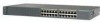
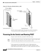
... 19X 20X 21X 22X Catalyst10209B0AS0ES-FEXRIES XL 23 24 10/100 ports 100BASE-FX ports Figure 1-3 Catalyst 2900 XL 100BASE-FX ports and Module Slots Expansion slots 47286 12 1 MODE 2 3 Catalyst 2900 SERIES XL 4 5 100BASE-FX 6 7 8 9 10 11 12 100BASE-FX ports Figure 1-4 Catalyst 2900 LRE XL 10/100 and LRE Ports INPUT OUTPUT PWR PWR RESET TEMP FAN 9X...
... 19X 20X 21X 22X Catalyst10209B0AS0ES-FEXRIES XL 23 24 10/100 ports 100BASE-FX ports Figure 1-3 Catalyst 2900 XL 100BASE-FX ports and Module Slots Expansion slots 47286 12 1 MODE 2 3 Catalyst 2900 SERIES XL 4 5 100BASE-FX 6 7 8 9 10 11 12 100BASE-FX ports Figure 1-4 Catalyst 2900 LRE XL 10/100 and LRE Ports INPUT OUTPUT PWR PWR RESET TEMP FAN 9X...

Hardware Installation Guide
Page 27
...-04 Catalyst 2900 Series XL Hardware Installation Guide 1-7 The default mode for full-duplex operation, the connection can be as plain old telephone service (POTS) splitter. For information about the Cisco LRE CPE devices, refer to the switch and private branch exchange (PBX) switch or Public-Switched Telephone Network (PSTN). The connection distances between the LRE switch port...
...-04 Catalyst 2900 Series XL Hardware Installation Guide 1-7 The default mode for full-duplex operation, the connection can be as plain old telephone service (POTS) splitter. For information about the Cisco LRE CPE devices, refer to the switch and private branch exchange (PBX) switch or Public-Switched Telephone Network (PSTN). The connection distances between the LRE switch port...

Hardware Installation Guide
Page 32
... LED colors during POST, see the "Powering On the Switch and Running POST" section on page 2-24. 1-12 Catalyst 2900 Series XL Hardware Installation Guide 78-6461-04 Front-Panel Description Figure 1-7 Catalyst 2912 LRE XL and 2924 LRE XL LEDs 10/100 port LEDs Chapter 1 Product Overview SYSTEM RPS MODE LRE STAT ...DUPLX SPEED Mode button 1X 2X 3X 4X System LED RPS LED LRE LED STAT LED DUPLEX LED Speed LED LRE port LEDs 1-12 LRE port LEDs 13-24 48002 System...
... LED colors during POST, see the "Powering On the Switch and Running POST" section on page 2-24. 1-12 Catalyst 2900 Series XL Hardware Installation Guide 78-6461-04 Front-Panel Description Figure 1-7 Catalyst 2912 LRE XL and 2924 LRE XL LEDs 10/100 port LEDs Chapter 1 Product Overview SYSTEM RPS MODE LRE STAT ...DUPLX SPEED Mode button 1X 2X 3X 4X System LED RPS LED LRE LED STAT LED DUPLEX LED Speed LED LRE port LEDs 1-12 LRE port LEDs 13-24 48002 System...

Hardware Installation Guide
Page 38
... -12.4%+ 12.5 -24%+ 25 - 49%+ 50%+ Catalyst 2900 SERIES XL 1-18 Catalyst 2900 Series XL Hardware Installation Guide 78-6461-04 The LEDs on Catalyst 2900 LRE XL switches with this release or higher, use the Port Settings window or the ...show remote interfaces status user EXEC command. The LEDs on Catalyst 2912 LRE XL and 2924 LRE XL Switches (continued) Port Mode SPEED Port LED Color Cisco...
... -12.4%+ 12.5 -24%+ 25 - 49%+ 50%+ Catalyst 2900 SERIES XL 1-18 Catalyst 2900 Series XL Hardware Installation Guide 78-6461-04 The LEDs on Catalyst 2900 LRE XL switches with this release or higher, use the Port Settings window or the ...show remote interfaces status user EXEC command. The LEDs on Catalyst 2912 LRE XL and 2924 LRE XL Switches (continued) Port Mode SPEED Port LED Color Cisco...

Hardware Installation Guide
Page 50
...24. Installation Guidelines The switch can be installed on a table or shelf, in the "Powering On the Switch and Running POST" section on a wall. Before installing the switch, first verify that does not have an on/off switch...full-duplex connections. Catalyst 2900 Series XL Hardware Installation Guide 2-6 78-6461-04 Class A equipment is operational by powering it on a system that the switch is designed for... . When determining where to place the switch, be sure to observe these guidelines: • For 10/100 ports, cable lengths from the switch to connected devices are up to 328 ...
...24. Installation Guidelines The switch can be installed on a table or shelf, in the "Powering On the Switch and Running POST" section on a wall. Before installing the switch, first verify that does not have an on/off switch...full-duplex connections. Catalyst 2900 Series XL Hardware Installation Guide 2-6 78-6461-04 Class A equipment is operational by powering it on a system that the switch is designed for... . When determining where to place the switch, be sure to observe these guidelines: • For 10/100 ports, cable lengths from the switch to connected devices are up to 328 ...

Hardware Installation Guide
Page 55
...24-inch rack. Chapter 2 Installation Installing the Switch in a Rack • "Attaching the Brackets to a Catalyst 2912 LRE XL or 2924 LRE XL Switch" section on page 2-16 • "Mounting the Switch in a Rack" section on page 2-18 • "Attaching the Optional Cable Guide" section on page 2-19 Removing Screws from the Switch Catalyst 2900 SERIES XL Fixed-port Catalyst... 2900 series XL Catalyst 2900 SERIES XL 22X 23X 24X Modular Catalyst 2900 series XL 47292 Attaching the Brackets to a Catalyst 2912 XL, 2924C...
...24-inch rack. Chapter 2 Installation Installing the Switch in a Rack • "Attaching the Brackets to a Catalyst 2912 LRE XL or 2924 LRE XL Switch" section on page 2-16 • "Mounting the Switch in a Rack" section on page 2-18 • "Attaching the Optional Cable Guide" section on page 2-19 Removing Screws from the Switch Catalyst 2900 SERIES XL Fixed-port Catalyst... 2900 series XL Catalyst 2900 SERIES XL 22X 23X 24X Modular Catalyst 2900 series XL 47292 Attaching the Brackets to a Catalyst 2912 XL, 2924C...
Hardware Installation Guide
Page 56
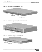
...XL, 2924C XL, and 2924 XL Fixed-Port Switches (Front-Panel Forward) Phillips flat-head screws Phillips truss-head screws 19" configuration MODE 1X 2X 3X 4X 5X 6X 7X 47738 23" and 24" configuration MODE 1X 2X 3X 4X 5X 6X 7X 2-12 Catalyst 2900 Series XL Hardware Installation Guide 78-6461-04 ...Installing the Switch in a Rack Chapter 2 Installation • For a 19-inch or a telco rack, use the ...
...XL, 2924C XL, and 2924 XL Fixed-Port Switches (Front-Panel Forward) Phillips flat-head screws Phillips truss-head screws 19" configuration MODE 1X 2X 3X 4X 5X 6X 7X 47738 23" and 24" configuration MODE 1X 2X 3X 4X 5X 6X 7X 2-12 Catalyst 2900 Series XL Hardware Installation Guide 78-6461-04 ...Installing the Switch in a Rack Chapter 2 Installation • For a 19-inch or a telco rack, use the ...

Hardware Installation Guide
Page 58
Installing the Switch in a Rack Chapter 2 Installation Figure 2-6 Attaching Brackets on Catalyst 2912 XL, 2924C XL, and 2924 XL Fixed-Port Switches (Rear-Panel Forward) 19" configuration Phillips flat-head screws 23" and 24" configuration Phillips truss-head screws 47298 2-14 Catalyst 2900 Series XL Hardware Installation Guide 78-6461-04
Installing the Switch in a Rack Chapter 2 Installation Figure 2-6 Attaching Brackets on Catalyst 2912 XL, 2924C XL, and 2924 XL Fixed-Port Switches (Rear-Panel Forward) 19" configuration Phillips flat-head screws 23" and 24" configuration Phillips truss-head screws 47298 2-14 Catalyst 2900 Series XL Hardware Installation Guide 78-6461-04
Hardware Installation Guide
Page 68
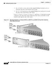
... Parallel wall-mount After the switch is mounted on the wall, power the switch as described in "Powering On the Switch and Running POST" section on page 2-24. Powering On the Switch and Running POST To power on the switch after you install it begins POST, a series of the AC power cord ...to the AC power connector on the switch. When the switch begins POST, the port LEDs turn amber for 2 seconds, and then they turn green. Catalyst 2900 Series XL ...
... Parallel wall-mount After the switch is mounted on the wall, power the switch as described in "Powering On the Switch and Running POST" section on page 2-24. Powering On the Switch and Running POST To power on the switch after you install it begins POST, a series of the AC power cord ...to the AC power connector on the switch. When the switch begins POST, the port LEDs turn amber for 2 seconds, and then they turn green. Catalyst 2900 Series XL ...
Hardware Installation Guide
Page 82
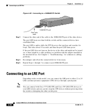
... Cisco 585 LRE CPE devices to connect each 100BASE-FX port. Connecting to an LRE Port Figure 2-29 Connecting to a 100BASE-FX Switch Chapter 2 Installation 47287 Catalyst10209B0AS0ES-FEXRIES XL 23 24 Step 3 Step 4 Step 5 100BASE-FX port Fiber-optic cable Connect the other end of the cable to the 100BASE-FX port of the other switch ports. 2-38 Catalyst 2900 Series...
... Cisco 585 LRE CPE devices to connect each 100BASE-FX port. Connecting to an LRE Port Figure 2-29 Connecting to a 100BASE-FX Switch Chapter 2 Installation 47287 Catalyst10209B0AS0ES-FEXRIES XL 23 24 Step 3 Step 4 Step 5 100BASE-FX port Fiber-optic cable Connect the other end of the cable to the 100BASE-FX port of the other switch ports. 2-38 Catalyst 2900 Series...

Hardware Installation Guide
Page 101
...(3.2 kg) Dimensions (H x W x D) Fiber-Port Power Levels 1.73 x 17.5 x 9.79 in. (4.4 x 44.5 x 24.8 cm) Optical transmitter - nm = nanometers 2. Transmit - 1. wavelength Optical sensibility of the - Appendix A Technical Specifications Table A-2 Technical Specifications for the Catalyst 2924 XL and Catalyst 2924C XL Switches Catalyst 2924 XL Environmental Operating Ranges Operating temperature 32 to ... DC input voltages 100 to 127/200 to 240 VAC (autoranging) 50 to -14 dBm 78-6461-04 Catalyst 2900 Series XL Hardware Installation Guide A-3 receiver Optical power transmitter -
...(3.2 kg) Dimensions (H x W x D) Fiber-Port Power Levels 1.73 x 17.5 x 9.79 in. (4.4 x 44.5 x 24.8 cm) Optical transmitter - nm = nanometers 2. Transmit - 1. wavelength Optical sensibility of the - Appendix A Technical Specifications Table A-2 Technical Specifications for the Catalyst 2924 XL and Catalyst 2924C XL Switches Catalyst 2924 XL Environmental Operating Ranges Operating temperature 32 to ... DC input voltages 100 to 127/200 to 240 VAC (autoranging) 50 to -14 dBm 78-6461-04 Catalyst 2900 Series XL Hardware Installation Guide A-3 receiver Optical power transmitter -

Hardware Installation Guide
Page 109
Note Table B-1 shows the pinouts for the console port. 78-6461-04 Catalyst 2900 Series XL Hardware Installation Guide B-5 On a Catalyst 2912 LRE XL switch, only circuits 1 to a console PC or terminal. Circuits 14, tip/ring 15, tip/ring 16, tip/ring 17, tip/ring 18, tip/ring 19, tip/...ring 20, tip/ring 21, tip/ring 22, tip/ring 23, tip/ring 24, tip/ring no connect - The following sections describe the rollover cable and adapters for the RJ-21 connector on a Catalyst 2924 LRE XL switch. Console Port The console port uses an 8-pin RJ-45 connector, as shown in Figure B-7 and described...
Note Table B-1 shows the pinouts for the console port. 78-6461-04 Catalyst 2900 Series XL Hardware Installation Guide B-5 On a Catalyst 2912 LRE XL switch, only circuits 1 to a console PC or terminal. Circuits 14, tip/ring 15, tip/ring 16, tip/ring 17, tip/ring 18, tip/ring 19, tip/...ring 20, tip/ring 21, tip/ring 22, tip/ring 23, tip/ring 24, tip/ring no connect - The following sections describe the rollover cable and adapters for the RJ-21 connector on a Catalyst 2924 LRE XL switch. Console Port The console port uses an 8-pin RJ-45 connector, as shown in Figure B-7 and described...
Hardware Installation Guide
Page 155
...full duplex 1-6 half duplex 1-6 pinouts B-2 100BASE-FX ports cables and connectors B-2 connecting to 2-37 to 2-38 connection distances, maximum 1-7 100 port mode LED 1-14 to 1-16 19-, 23-, and 24-inch racks 2-9 A AC power connecting to 2-24 connector 1-21 warning C-1 to C-4 78-6461-04 ...-T ports B-1 to B-2, B-4 100BASE-FX, 50/125- or 62.5/125-micron fiber-optic 2-37, B-2 crossover and straight-through pinouts B-4 RJ-21 pinouts B-5 rollover B-6 rollover pinouts DB-25 adapter B-8 CCO See Cisco.com chassis, warning against stacking C-7 circuit breaker (15A) warning C-12 Catalyst 2900 Series XL...
...full duplex 1-6 half duplex 1-6 pinouts B-2 100BASE-FX ports cables and connectors B-2 connecting to 2-37 to 2-38 connection distances, maximum 1-7 100 port mode LED 1-14 to 1-16 19-, 23-, and 24-inch racks 2-9 A AC power connecting to 2-24 connector 1-21 warning C-1 to C-4 78-6461-04 ...-T ports B-1 to B-2, B-4 100BASE-FX, 50/125- or 62.5/125-micron fiber-optic 2-37, B-2 crossover and straight-through pinouts B-4 RJ-21 pinouts B-5 rollover B-6 rollover pinouts DB-25 adapter B-8 CCO See Cisco.com chassis, warning against stacking C-7 circuit breaker (15A) warning C-12 Catalyst 2900 Series XL...
Hardware Installation Guide
Page 156
Index Cisco.com xviii Cisco RPS See RPS CiscoWorks 2000 1-4 Class 1 laser product warning C-22 CLI 1-4 Cluster Management Suite See CMS CMS 1-4 command-line interface See CLI connecting 10/100 ports to IP Phones 2-35 to 2-36 connecting to 10/100BASE-T ports 2-35 100BASE-FX ports 2-37 to 2-38 AC power 2-24 console port 2-42 to 2-...document xii crossover cable connectivity problems 3-5 pinout B-4 D DC power connecting to 2-25 to 2-35 specifications A-5 warning C-29 to C-30, C-39 default characteristics of the console port 2-42 IN-2 Catalyst 2900 Series XL Hardware Installation Guide 78-6461-04
Index Cisco.com xviii Cisco RPS See RPS CiscoWorks 2000 1-4 Class 1 laser product warning C-22 CLI 1-4 Cluster Management Suite See CMS CMS 1-4 command-line interface See CLI connecting 10/100 ports to IP Phones 2-35 to 2-36 connecting to 10/100BASE-T ports 2-35 100BASE-FX ports 2-37 to 2-38 AC power 2-24 console port 2-42 to 2-...document xii crossover cable connectivity problems 3-5 pinout B-4 D DC power connecting to 2-25 to 2-35 specifications A-5 warning C-29 to C-30, C-39 default characteristics of the console port 2-42 IN-2 Catalyst 2900 Series XL Hardware Installation Guide 78-6461-04

Hardware Installation Guide
Page 158
... 1-16 expansion slots 1-19 FDUP 1-14 to 1-16 full duplex 1-16 half duplex 1-16 interpreting 1-14 LRE 1-15 port (Catalyst 2900 LRE XL) 1-17 port status 1-9, 1-16 to 1-18 POST results 2-24, 3-1 RPS 1-13 to 1-14 RPS 600 1-13 SPEED 1-15 STAT 1-14 to 1-17 STAT LED 1-16 System ... 1-14, 1-16 lightning activity warning C-19 Long-Reach Ethernet See LRE LRE defined 1-1 LED 1-15 port connecting to 2-38 to 2-41 See also RJ-21 connector M main disconnecting device warning C-8 maximum connection distances See connection distances, maximum IN-4 Catalyst 2900 Series XL Hardware Installation Guide 78-6461-04
... 1-16 expansion slots 1-19 FDUP 1-14 to 1-16 full duplex 1-16 half duplex 1-16 interpreting 1-14 LRE 1-15 port (Catalyst 2900 LRE XL) 1-17 port status 1-9, 1-16 to 1-18 POST results 2-24, 3-1 RPS 1-13 to 1-14 RPS 600 1-13 SPEED 1-15 STAT 1-14 to 1-17 STAT LED 1-16 System ... 1-14, 1-16 lightning activity warning C-19 Long-Reach Ethernet See LRE LRE defined 1-1 LED 1-15 port connecting to 2-38 to 2-41 See also RJ-21 connector M main disconnecting device warning C-8 maximum connection distances See connection distances, maximum IN-4 Catalyst 2900 Series XL Hardware Installation Guide 78-6461-04
Hardware Installation Guide
Page 159
... 2-9 attaching 2-11, 2-15, 2-22 N no on/off switch warning C-24 O overtemperature warning C-9 P PC, connecting to switch 2-42 performance problems, solving 3-3 personnel warning C-3 pinouts 10/100BASE-T ports B-2 cable, straight-through and crossover B-4 RJ-21 connector B-5 ...port status LEDs 1-9, 1-16 to 1-18 port status LEDs 1-9, 1-16 to 1-18 POST results 2-24 power connecting to 2-24 warning C-15 power connectors 1-21 power on 2-24 power supply AC power outlet 1-21 RPS connector 1-21 warning C-17 product disposal warning C-21 Q qualified personnel warning C-3 78-6461-04 Catalyst 2900 Series...
... 2-9 attaching 2-11, 2-15, 2-22 N no on/off switch warning C-24 O overtemperature warning C-9 P PC, connecting to switch 2-42 performance problems, solving 3-3 personnel warning C-3 pinouts 10/100BASE-T ports B-2 cable, straight-through and crossover B-4 RJ-21 connector B-5 ...port status LEDs 1-9, 1-16 to 1-18 port status LEDs 1-9, 1-16 to 1-18 POST results 2-24 power connecting to 2-24 warning C-15 power connectors 1-21 power on 2-24 power supply AC power outlet 1-21 RPS connector 1-21 warning C-17 product disposal warning C-21 Q qualified personnel warning C-3 78-6461-04 Catalyst 2900 Series...
Hardware Installation Guide
Page 160
... Manager 1-4 supply circuit warning C-15 switch powering on 2-24 switched ports, module 1-8 System LED 1-12 T telco racks 2-15 telephone network power warning See TN power warning C-10 temperature maximum for installation 2-7, A-2 warning C-9 temperature warning C-9 terminal, connecting to switch 2-42 terminal adapter pinouts RH-45-to-RJ-45 B-7 IN-6 Catalyst 2900 Series XL Hardware Installation Guide 78-6461...
... Manager 1-4 supply circuit warning C-15 switch powering on 2-24 switched ports, module 1-8 System LED 1-12 T telco racks 2-15 telephone network power warning See TN power warning C-10 temperature maximum for installation 2-7, A-2 warning C-9 temperature warning C-9 terminal, connecting to switch 2-42 terminal adapter pinouts RH-45-to-RJ-45 B-7 IN-6 Catalyst 2900 Series XL Hardware Installation Guide 78-6461...

