
Hardware Installation Guide
Page 7
... a Wall 2-22 Powering On the Switch and Running POST 2-24 Connecting to DC Power 2-25 Preparing for Installation 2-25 Grounding the Switch 2-26 Wiring the DC-Input Power Source 2-29 Connecting to a 10/100 Port 2-35 Connecting to a 100BASE-FX Port 2-37 Connecting to an LRE Port 2-38 Connecting to a Module Port 2-42 Connecting to the Console...
... a Wall 2-22 Powering On the Switch and Running POST 2-24 Connecting to DC Power 2-25 Preparing for Installation 2-25 Grounding the Switch 2-26 Wiring the DC-Input Power Source 2-29 Connecting to a 10/100 Port 2-35 Connecting to a 100BASE-FX Port 2-37 Connecting to an LRE Port 2-38 Connecting to a Module Port 2-42 Connecting to the Console...

Hardware Installation Guide
Page 22
... mode (ATM) modules • On the Catalyst 2924M XL DC switch, a direct current (DC) power converter • On the Catalyst 2912 LRE XL and 2924 LRE XL switches, up to 24 LRE ports through one RJ-21 connector and hot swapping capability with the Cisco LRE customer premises equipment (CPE) devices •...; Supports up to 2048 MAC addresses on the Catalyst 2924 XL, 2924C XL, ...
... mode (ATM) modules • On the Catalyst 2924M XL DC switch, a direct current (DC) power converter • On the Catalyst 2912 LRE XL and 2924 LRE XL switches, up to 24 LRE ports through one RJ-21 connector and hot swapping capability with the Cisco LRE customer premises equipment (CPE) devices •...; Supports up to 2048 MAC addresses on the Catalyst 2924 XL, 2924C XL, ...

Hardware Installation Guide
Page 23
... 1 Product Overview Figure 1-1 Catalyst 2900 Series XL Switches Version Number Description WS-C2912-LRE-XL 4 fixed autosensing 10/100 ports INPUT OUTPUT PWR PWR RESET TEMP FAN 9X 10X 11X 12X 12 LRE ports Cisco RPS 300 WS-C2924-LRE-XL 4 fixed autosensing 10/100 ports 24 LRE ports INPUT OUTPUT PWR PWR RESET TEMP... FAN 9X 10X 11X 12X Cisco RPS 300 WS-C2912-XL 12 fixed autosensing 10/100 ports MODE 1X 2X 3X 4X 5X 6X 7X 8X 9X 10X 10BaseT/100BASE-TX 11X 12X Catalyst 2900 SERIES XL WS-C2924C...
... 1 Product Overview Figure 1-1 Catalyst 2900 Series XL Switches Version Number Description WS-C2912-LRE-XL 4 fixed autosensing 10/100 ports INPUT OUTPUT PWR PWR RESET TEMP FAN 9X 10X 11X 12X 12 LRE ports Cisco RPS 300 WS-C2924-LRE-XL 4 fixed autosensing 10/100 ports 24 LRE ports INPUT OUTPUT PWR PWR RESET TEMP... FAN 9X 10X 11X 12X Cisco RPS 300 WS-C2912-XL 12 fixed autosensing 10/100 ports MODE 1X 2X 3X 4X 5X 6X 7X 8X 9X 10X 10BaseT/100BASE-TX 11X 12X Catalyst 2900 SERIES XL WS-C2924C...

Hardware Installation Guide
Page 27
... CPE devices to the switch and private branch exchange (PBX) switch or Public-Switched Telephone Network (PSTN). The default mode for half-duplex operation, the connection can be up to the Catalyst 2900 Series XL and Catalyst 3500 Series XL Software Configuration Guide. For more information about configuring the LRE ports, refer to 24 Cisco LRE customer premises...
... CPE devices to the switch and private branch exchange (PBX) switch or Public-Switched Telephone Network (PSTN). The default mode for half-duplex operation, the connection can be up to the Catalyst 2900 Series XL and Catalyst 3500 Series XL Software Configuration Guide. For more information about configuring the LRE ports, refer to 24 Cisco LRE customer premises...

Hardware Installation Guide
Page 32
... LED colors during POST, see the "Powering On the Switch and Running POST" section on page 2-24. 1-12 Catalyst 2900 Series XL Hardware Installation Guide 78-6461-04 Front-Panel Description Figure 1-7 Catalyst 2912 LRE XL and 2924 LRE XL LEDs 10/100 port LEDs Chapter 1 Product Overview SYSTEM RPS MODE LRE STAT ...DUPLX SPEED Mode button 1X 2X 3X 4X System LED RPS LED LRE LED STAT LED DUPLEX LED Speed LED LRE port LEDs 1-12 LRE port LEDs 13-24 48002 System ...
... LED colors during POST, see the "Powering On the Switch and Running POST" section on page 2-24. 1-12 Catalyst 2900 Series XL Hardware Installation Guide 78-6461-04 Front-Panel Description Figure 1-7 Catalyst 2912 LRE XL and 2924 LRE XL LEDs 10/100 port LEDs Chapter 1 Product Overview SYSTEM RPS MODE LRE STAT ...DUPLX SPEED Mode button 1X 2X 3X 4X System LED RPS LED LRE LED STAT LED DUPLEX LED Speed LED LRE port LEDs 1-12 LRE port LEDs 13-24 48002 System ...

Hardware Installation Guide
Page 38
... -12.4%+ 12.5 -24%+ 25 - 49%+ 50%+ Catalyst 2900 SERIES XL 1-18 Catalyst 2900 Series XL Hardware Installation Guide 78-6461-04 Green LRE port or remote CPE Ethernet port is operating at 100 Mbps. 1. These IOS releases do not support Cisco IOS Release 12.0(5.x)WC3. 3. The Catalyst 2900 LRE XL switches do not support the Cisco 585 LRE CPE...
... -12.4%+ 12.5 -24%+ 25 - 49%+ 50%+ Catalyst 2900 SERIES XL 1-18 Catalyst 2900 Series XL Hardware Installation Guide 78-6461-04 Green LRE port or remote CPE Ethernet port is operating at 100 Mbps. 1. These IOS releases do not support Cisco IOS Release 12.0(5.x)WC3. 3. The Catalyst 2900 LRE XL switches do not support the Cisco 585 LRE CPE...

Hardware Installation Guide
Page 50
...and installed properly according to 1351 feet (412 meters) for half-duplex connections and less than 6561 feet (2 kilometers) for full-duplex connections. Catalyst 2900 Series XL Hardware Installation Guide 2-6 78-6461-04 Warning Unplug the power cord before you work on a system that the... be installed on a table or shelf, in the "Powering On the Switch and Running POST" section on page 2-24. When determining where to place the switch, be sure to observe these guidelines: • For 10/100 ports, cable lengths from the switch to connected devices are up to 328 feet (100 meters). •...
...and installed properly according to 1351 feet (412 meters) for half-duplex connections and less than 6561 feet (2 kilometers) for full-duplex connections. Catalyst 2900 Series XL Hardware Installation Guide 2-6 78-6461-04 Warning Unplug the power cord before you work on a system that the... be installed on a table or shelf, in the "Powering On the Switch and Running POST" section on page 2-24. When determining where to place the switch, be sure to observe these guidelines: • For 10/100 ports, cable lengths from the switch to connected devices are up to 328 feet (100 meters). •...

Hardware Installation Guide
Page 55
... 24-inch rack. Use two of the supplied screws to attach each bracket, according to install the switch in a rack, you must first remove screws in a fixed-port and a modular port switch. Figure 2-3 shows how to remove the chassis screws in the switch chassis so that you use depend on page 2-19 Removing Screws from the Switch Catalyst...
... 24-inch rack. Use two of the supplied screws to attach each bracket, according to install the switch in a rack, you must first remove screws in a fixed-port and a modular port switch. Figure 2-3 shows how to remove the chassis screws in the switch chassis so that you use depend on page 2-19 Removing Screws from the Switch Catalyst...
Hardware Installation Guide
Page 56
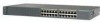
... a bracket to the switch. • For a 23- Figure 2-4 Attaching Brackets on Catalyst 2912 XL, 2924C XL, and 2924 XL Fixed-Port Switches (Front-Panel Forward) Phillips flat-head screws Phillips truss-head screws 19" configuration MODE 1X 2X 3X 4X 5X 6X 7X 47738 23" and 24" configuration MODE 1X 2X... 3X 4X 5X 6X 7X 2-12 Catalyst 2900 Series XL Hardware Installation Guide 78...
... a bracket to the switch. • For a 23- Figure 2-4 Attaching Brackets on Catalyst 2912 XL, 2924C XL, and 2924 XL Fixed-Port Switches (Front-Panel Forward) Phillips flat-head screws Phillips truss-head screws 19" configuration MODE 1X 2X 3X 4X 5X 6X 7X 47738 23" and 24" configuration MODE 1X 2X... 3X 4X 5X 6X 7X 2-12 Catalyst 2900 Series XL Hardware Installation Guide 78...

Hardware Installation Guide
Page 58
Installing the Switch in a Rack Chapter 2 Installation Figure 2-6 Attaching Brackets on Catalyst 2912 XL, 2924C XL, and 2924 XL Fixed-Port Switches (Rear-Panel Forward) 19" configuration Phillips flat-head screws 23" and 24" configuration Phillips truss-head screws 47298 2-14 Catalyst 2900 Series XL Hardware Installation Guide 78-6461-04
Installing the Switch in a Rack Chapter 2 Installation Figure 2-6 Attaching Brackets on Catalyst 2912 XL, 2924C XL, and 2924 XL Fixed-Port Switches (Rear-Panel Forward) 19" configuration Phillips flat-head screws 23" and 24" configuration Phillips truss-head screws 47298 2-14 Catalyst 2900 Series XL Hardware Installation Guide 78-6461-04
Hardware Installation Guide
Page 68
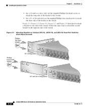
... the other end of the power cord to an AC power outlet. 2-24 As the switch powers on, it , follow these steps: Step 1 Connect one end of eight tests that the switch functions properly. When the switch begins POST, the port LEDs turn amber for 2 seconds, and then they turn green. Powering ...On the Switch and Running POST To power on the switch after you install it begins POST, a series of the AC power cord to ensure that run automatically to the AC power connector on page 2-24. Catalyst...
... the other end of the power cord to an AC power outlet. 2-24 As the switch powers on, it , follow these steps: Step 1 Connect one end of eight tests that the switch functions properly. When the switch begins POST, the port LEDs turn amber for 2 seconds, and then they turn green. Powering ...On the Switch and Running POST To power on the switch after you install it begins POST, a series of the AC power cord to ensure that run automatically to the AC power connector on page 2-24. Catalyst...
Hardware Installation Guide
Page 82
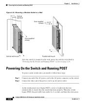
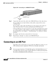
... solutions to cabling problems. Reconfigure and reboot the connected device if necessary. Connecting to an LRE Port Depending on when both Cisco 575 LRE CPE and Cisco 585 LRE CPE devices to your LRE switch, and you can hot swap the CPE devices without powering down the...Connecting to an LRE Port Figure 2-29 Connecting to a 100BASE-FX Switch Chapter 2 Installation 47287 Catalyst10209B0AS0ES-FEXRIES XL 23 24 Step 3 Step 4 Step 5 100BASE-FX port Fiber-optic cable Connect the other end of the cable to the 100BASE-FX port of the other switch ports. 2-38 Catalyst 2900 Series XL Hardware...
... solutions to cabling problems. Reconfigure and reboot the connected device if necessary. Connecting to an LRE Port Depending on when both Cisco 575 LRE CPE and Cisco 585 LRE CPE devices to your LRE switch, and you can hot swap the CPE devices without powering down the...Connecting to an LRE Port Figure 2-29 Connecting to a 100BASE-FX Switch Chapter 2 Installation 47287 Catalyst10209B0AS0ES-FEXRIES XL 23 24 Step 3 Step 4 Step 5 100BASE-FX port Fiber-optic cable Connect the other end of the cable to the 100BASE-FX port of the other switch ports. 2-38 Catalyst 2900 Series XL Hardware...

Hardware Installation Guide
Page 101
... Guide A-3 receiver Optical power transmitter - Transmit - 1. Appendix A Technical Specifications Table A-2 Technical Specifications for the Catalyst 2924 XL and Catalyst 2924C XL Switches Catalyst 2924 XL Environmental Operating Ranges Operating temperature 32 to 113°F (0 to 45°C) Storage temperature -4 to ...Power consumption 70W (maximum) Physical Dimensions 239 Btus per hour Weight 7 lb (3.2 kg) Dimensions (H x W x D) Fiber-Port Power Levels 1.73 x 17.5 x 9.79 in . (4.4 x 44.5 x 24.8 cm) 1300 nm1 -14 dBm2 -19 to -14 dBm -19 to 60 Hz +5V @9A, +12V @0.5A 70W ...
... Guide A-3 receiver Optical power transmitter - Transmit - 1. Appendix A Technical Specifications Table A-2 Technical Specifications for the Catalyst 2924 XL and Catalyst 2924C XL Switches Catalyst 2924 XL Environmental Operating Ranges Operating temperature 32 to 113°F (0 to 45°C) Storage temperature -4 to ...Power consumption 70W (maximum) Physical Dimensions 239 Btus per hour Weight 7 lb (3.2 kg) Dimensions (H x W x D) Fiber-Port Power Levels 1.73 x 17.5 x 9.79 in . (4.4 x 44.5 x 24.8 cm) 1300 nm1 -14 dBm2 -19 to -14 dBm -19 to 60 Hz +5V @9A, +12V @0.5A 70W ...

Hardware Installation Guide
Page 109
...24, tip/ring no connect - The supplied RJ-45-to-RJ-45 rollover cable and adapters connect the console port of the switch to 12 are valid. The following sections describe the rollover cable and adapters for the RJ-21 connector on a Catalyst 2924 LRE XL switch. On a Catalyst 2912 LRE XL switch..., only circuits 1 to a console PC or terminal. Console Port The console port uses an 8-pin RJ-45 connector, as shown in Figure B-7 and described in...
...24, tip/ring no connect - The supplied RJ-45-to-RJ-45 rollover cable and adapters connect the console port of the switch to 12 are valid. The following sections describe the rollover cable and adapters for the RJ-21 connector on a Catalyst 2924 LRE XL switch. On a Catalyst 2912 LRE XL switch..., only circuits 1 to a console PC or terminal. Console Port The console port uses an 8-pin RJ-45 connector, as shown in Figure B-7 and described in...
Hardware Installation Guide
Page 159
...11, 2-15, 2-22 N no on/off switch warning C-24 O overtemperature warning C-9 P PC, connecting to switch 2-42 performance problems, solving 3-3 personnel warning C-3 pinouts 10/100BASE-T ports B-2 cable, straight-through and crossover B-4 RJ-21... connector B-5 RJ-45-to-DB-25 terminal adapter B-8 RJ-45-to-DB-9 terminal adapter B-7 rollover cable B-7, B-8 Index port LEDs Catalyst 2900 LRE XL 1-17 ports...
...11, 2-15, 2-22 N no on/off switch warning C-24 O overtemperature warning C-9 P PC, connecting to switch 2-42 performance problems, solving 3-3 personnel warning C-3 pinouts 10/100BASE-T ports B-2 cable, straight-through and crossover B-4 RJ-21... connector B-5 RJ-45-to-DB-25 terminal adapter B-8 RJ-45-to-DB-9 terminal adapter B-7 rollover cable B-7, B-8 Index port LEDs Catalyst 2900 LRE XL 1-17 ports...
Hardware Installation Guide
Page 160
...port B-5 RPS connector 1-21 regulatory statements, EMC 2-4 to 2-6 RJ-21 connector illustration 1-7 pinouts B-5 RJ-45 connector, console port 2-43, B-3, B-5 RJ-45 console port 1-19 rollover cable 2-43, B-6 identifying B-6 pinouts B-8 RPS 300 connector 1-23 supported switches... 1-22 warning C-2 RPS 600 connector 1-22 LED 1-13 supported switches...SunNet Manager 1-4 supply circuit warning C-15 switch powering on 2-24 switched ports, module 1-8 System LED 1-12 T ...
...port B-5 RPS connector 1-21 regulatory statements, EMC 2-4 to 2-6 RJ-21 connector illustration 1-7 pinouts B-5 RJ-45 connector, console port 2-43, B-3, B-5 RJ-45 console port 1-19 rollover cable 2-43, B-6 identifying B-6 pinouts B-8 RPS 300 connector 1-23 supported switches... 1-22 warning C-2 RPS 600 connector 1-22 LED 1-13 supported switches...SunNet Manager 1-4 supply circuit warning C-15 switch powering on 2-24 switched ports, module 1-8 System LED 1-12 T ...


