
User Guide
Page 3
Figure 1-1 Model 2501 Router Rear Panel Ethernet AUI LED Synchronous serial LEDs System OK LED Hardware Features H4262 Ethernet AUI port (DB-15) Synchronous serial ports (DB-60) Console port (RJ-45) On/off Power switch Auxiliary port (RJ-45) Figure 1-2 Model 2502 Router Rear Panel Token Ring Synchronous LED serial LEDs System OK LED H6585 Token Ring port (DB-9) Synchronous serial ports (DB-60) Console port (RJ-45) On/off Power switch Auxiliary port (RJ-45) Overview of the Router 1-3
Figure 1-1 Model 2501 Router Rear Panel Ethernet AUI LED Synchronous serial LEDs System OK LED Hardware Features H4262 Ethernet AUI port (DB-15) Synchronous serial ports (DB-60) Console port (RJ-45) On/off Power switch Auxiliary port (RJ-45) Figure 1-2 Model 2502 Router Rear Panel Token Ring Synchronous LED serial LEDs System OK LED H6585 Token Ring port (DB-9) Synchronous serial ports (DB-60) Console port (RJ-45) On/off Power switch Auxiliary port (RJ-45) Overview of the Router 1-3

User Guide
Page 4
... LED Ethernet AUI port (DB-15) Synchronous serial ports (DB-60) Console port (RJ-45) On/off Power switch ISDN BRI port (RJ-45) Auxiliary port (RJ-45) Figure 1-4 Model 2504 Router Rear Panel Token Ring Synchronous ISDN System LED serial LEDs BRI LED OK LED Token Ring port (DB-9) Synchronous... serial ports (DB-60) Console port (RJ-45) On/off Power switch ISDN BRI port (RJ-45) Auxiliary port (RJ-45) H6587...
... LED Ethernet AUI port (DB-15) Synchronous serial ports (DB-60) Console port (RJ-45) On/off Power switch ISDN BRI port (RJ-45) Auxiliary port (RJ-45) Figure 1-4 Model 2504 Router Rear Panel Token Ring Synchronous ISDN System LED serial LEDs BRI LED OK LED Token Ring port (DB-9) Synchronous... serial ports (DB-60) Console port (RJ-45) On/off Power switch ISDN BRI port (RJ-45) Auxiliary port (RJ-45) H6587...

User Guide
Page 5
Figure 1-5 Model 2513 Router Rear Panel Token Ring Ethernet Synchronous LED AUI LED serial LEDs System OK LED TOKEN RING Token Ring port (DB-9) Ethernet AUI port (DB-15) Synchronous serial ports (DB-60) Console port (RJ-45) On/off switch Auxiliary port (RJ-45) Power Figure 1-6 Model 2514 Router Rear Panel Ethernet AUI LEDs Synchronous serial LEDs System OK LED Hardware Features H6588 H6589 Ethernet AUI ports (DB-15) Synchronous serial ports (DB-60) Console port (RJ-45) On/off switch Auxiliary port (RJ-45) Power Overview of the Router 1-5
Figure 1-5 Model 2513 Router Rear Panel Token Ring Ethernet Synchronous LED AUI LED serial LEDs System OK LED TOKEN RING Token Ring port (DB-9) Ethernet AUI port (DB-15) Synchronous serial ports (DB-60) Console port (RJ-45) On/off switch Auxiliary port (RJ-45) Power Figure 1-6 Model 2514 Router Rear Panel Ethernet AUI LEDs Synchronous serial LEDs System OK LED Hardware Features H6588 H6589 Ethernet AUI ports (DB-15) Synchronous serial ports (DB-60) Console port (RJ-45) On/off switch Auxiliary port (RJ-45) Power Overview of the Router 1-5

User Guide
Page 6
...LED H6590 Token Ring ports (DB-9) Synchronous serial ports (DB-60) Console port (RJ-45) On/off Power switch Auxiliary port (RJ-45) System Specifications The system specifications of the routers are listed in . (4.44 x 44.45 x 26.82 cm), one rack unit 10 lb (4.5 kg) ... Hz 40W (maximum), 135.5 Btus1/hr 40W, 40 to 72 VDC 1.5 to 1.0A 40W (maximum), 135.5 Btus/hr 20-MHz Motorola 68EC030 1-6 Router Installation and Configuration Guide Table 1-2 System Specifications Description Dimensions (H x W x D) Weight Input voltage, AC power supply Current Frequency Power dissipation Input voltage, DC...
...LED H6590 Token Ring ports (DB-9) Synchronous serial ports (DB-60) Console port (RJ-45) On/off Power switch Auxiliary port (RJ-45) System Specifications The system specifications of the routers are listed in . (4.44 x 44.45 x 26.82 cm), one rack unit 10 lb (4.5 kg) ... Hz 40W (maximum), 135.5 Btus1/hr 40W, 40 to 72 VDC 1.5 to 1.0A 40W (maximum), 135.5 Btus/hr 20-MHz Motorola 68EC030 1-6 Router Installation and Configuration Guide Table 1-2 System Specifications Description Dimensions (H x W x D) Weight Input voltage, AC power supply Current Frequency Power dissipation Input voltage, DC...

Getting Started Guide
Page 6
... is designed so that 1500 VAC rms isolation (per the 802.3 specification) is configured to reset the POE controller, it can be used for infra-switch connection using multiple an AP-Manager or data interface. 6 This interface supports the proper voltage isolation as defined by 802.3. LED description: • Green or...
... is designed so that 1500 VAC rms isolation (per the 802.3 specification) is configured to reset the POE controller, it can be used for infra-switch connection using multiple an AP-Manager or data interface. 6 This interface supports the proper voltage isolation as defined by 802.3. LED description: • Green or...

Getting Started Guide
Page 13
...: Step 1 Attach the 19-inch brackets to each side of space around the controller ventilation openings to prevent airflow restriction and overheating. Step 3 Place the switch on a wall using an optional rack-mount bracket kit that is AIR-CT2504-RMNT. You can be mounted on page 23. Statement 378 To mount... near an AC power source. Note Allow 3 inches of the 2504 controller as shown in Figure 5 with 19-inch rack mounting brackets and hardware from Cisco.
...: Step 1 Attach the 19-inch brackets to each side of space around the controller ventilation openings to prevent airflow restriction and overheating. Step 3 Place the switch on a wall using an optional rack-mount bracket kit that is AIR-CT2504-RMNT. You can be mounted on page 23. Statement 378 To mount... near an AC power source. Note Allow 3 inches of the 2504 controller as shown in Figure 5 with 19-inch rack mounting brackets and hardware from Cisco.
Getting Started Guide
Page 25
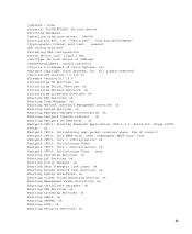
... Initialization: ok Fastpath CPU00: Initializing Timer...done. Flags-[DUTY CYCLE] : ok Fastpath CPU00: Initializing last packet received queue. Starting Switching Services: ok Starting QoS Services: ok Starting Policy Manager: ok Starting Data Transport Link Layer: ok Starting Access Control List Services... ether-pow driver - 0x6008 starting pid 805, tty '/dev/ttyS0': '/usr/bin/gettyOrMwar' Cryptographic library self-test....passed! Cisco AireOS Version 7.0.114.76 Firmware Version PIC 14.0 Initializing OS Services: ok Initializing Serial Services: ok Initializing Network Services: ok...
... Initialization: ok Fastpath CPU00: Initializing Timer...done. Flags-[DUTY CYCLE] : ok Fastpath CPU00: Initializing last packet received queue. Starting Switching Services: ok Starting QoS Services: ok Starting Policy Manager: ok Starting Data Transport Link Layer: ok Starting Access Control List Services... ether-pow driver - 0x6008 starting pid 805, tty '/dev/ttyS0': '/usr/bin/gettyOrMwar' Cryptographic library self-test....passed! Cisco AireOS Version 7.0.114.76 Firmware Version PIC 14.0 Initializing OS Services: ok Initializing Serial Services: ok Initializing Network Services: ok...

Getting Started Guide
Page 28
SDK-1.8.0, build 269. Starting Switching Services: ok Starting QoS Services: ok Starting Policy Manager: ok Starting Data Transport Link Layer: ok Starting Access Control List Services: ok Starting System Interfaces: ... Manager: ok Starting Authentication Engine: ok Starting Mobility Management: ok Starting Virtual AP Services: ok Starting AireWave Director: ok Starting Network Time Services: ok Starting Cisco Discovery Protocol: ok Starting Broadcast Services: ok Starting Logging Services: ok Starting DHCP Server: ok Starting IDS Signature Manager: ok Starting RFID Tag Tracking: ok...
SDK-1.8.0, build 269. Starting Switching Services: ok Starting QoS Services: ok Starting Policy Manager: ok Starting Data Transport Link Layer: ok Starting Access Control List Services: ok Starting System Interfaces: ... Manager: ok Starting Authentication Engine: ok Starting Mobility Management: ok Starting Virtual AP Services: ok Starting AireWave Director: ok Starting Network Time Services: ok Starting Cisco Discovery Protocol: ok Starting Broadcast Services: ok Starting Logging Services: ok Starting DHCP Server: ok Starting IDS Signature Manager: ok Starting RFID Tag Tracking: ok...
Getting Started Guide
Page 30
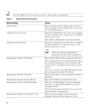
... to this controller. Enter the IP address of the access point manager interface. Enter the port number of the default router. The management interface is no default administrative password, you must enter a password. Enter the IP address of the management... interface. Management Interface IP Address Management Interface Netmask Management Interface Default Router Management Interface VLAN Identifier Management Interface Port Num [1 to match the switch interface configuration. Enter the IP address of the management interface netmask. Enter the VLAN ...
... to this controller. Enter the IP address of the access point manager interface. Enter the port number of the default router. The management interface is no default administrative password, you must enter a password. Enter the IP address of the management... interface. Management Interface IP Address Management Interface Netmask Management Interface Default Router Management Interface VLAN Identifier Management Interface Port Num [1 to match the switch interface configuration. Enter the IP address of the management interface netmask. Enter the VLAN ...
Getting Started Guide
Page 35
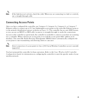
... access that are scanning for information on configuring the controller to the Cisco Wireless LAN Controller Configuration Guide for a controller. Refer to meet the specific needs of access points to Cisco 2500 Series Wireless Controllers are connecting to make the connections. As soon...14. You have configured the controller, use a straight-through ) to a hub or a switch, use Category-5, Category-5e, Category-6, or Category-7 Ethernet cables to connect up to 50 Cisco lightweight access points to the controller Ethernet ports or to associate. Connecting Access Points After you...
... access that are scanning for information on configuring the controller to the Cisco Wireless LAN Controller Configuration Guide for a controller. Refer to meet the specific needs of access points to Cisco 2500 Series Wireless Controllers are connecting to make the connections. As soon...14. You have configured the controller, use a straight-through ) to a hub or a switch, use Category-5, Category-5e, Category-6, or Category-7 Ethernet cables to connect up to 50 Cisco lightweight access points to the controller Ethernet ports or to associate. Connecting Access Points After you...

User Guide
Page 7
Figure 1-1 Model 2501 Router Rear Panel Ethernet AUI LED Synchronous serial LEDs System OK LED Hardware Features H4262 Ethernet AUI port (DB-15) Synchronous serial ports (DB-60) Console port (RJ-45) On/off Power switch Auxiliary port (RJ-45) Figure 1-2 Model 2502 Router Rear Panel Token Ring Synchronous LED serial LEDs System OK LED H6585 Token Ring port (DB-9) Synchronous serial ports (DB-60) Console port (RJ-45) On/off Power switch Auxiliary port (RJ-45) Overview of the Router 1-3
Figure 1-1 Model 2501 Router Rear Panel Ethernet AUI LED Synchronous serial LEDs System OK LED Hardware Features H4262 Ethernet AUI port (DB-15) Synchronous serial ports (DB-60) Console port (RJ-45) On/off Power switch Auxiliary port (RJ-45) Figure 1-2 Model 2502 Router Rear Panel Token Ring Synchronous LED serial LEDs System OK LED H6585 Token Ring port (DB-9) Synchronous serial ports (DB-60) Console port (RJ-45) On/off Power switch Auxiliary port (RJ-45) Overview of the Router 1-3

User Guide
Page 8
... LED Ethernet AUI port (DB-15) Synchronous serial ports (DB-60) Console port (RJ-45) On/off Power switch ISDN Auxiliary port BRI port (RJ-45) (RJ-45) Figure 1-4 Model 2504 Router Rear Panel Token Ring Synchronous ISDN System LED serial LEDs BRI LED OK LED Token Ring port (DB-9) Synchronous... serial ports (DB-60) Console port (RJ-45) On/off Power switch ISDN BRI port (RJ-45) Auxiliary port (RJ-45) H6587...
... LED Ethernet AUI port (DB-15) Synchronous serial ports (DB-60) Console port (RJ-45) On/off Power switch ISDN Auxiliary port BRI port (RJ-45) (RJ-45) Figure 1-4 Model 2504 Router Rear Panel Token Ring Synchronous ISDN System LED serial LEDs BRI LED OK LED Token Ring port (DB-9) Synchronous... serial ports (DB-60) Console port (RJ-45) On/off Power switch ISDN BRI port (RJ-45) Auxiliary port (RJ-45) H6587...

User Guide
Page 9
Figure 1-5 Model 2513 Router Rear Panel Token Ring Ethernet Synchronous LED AUI LED serial LEDs System OK LED TOKEN RING Token Ring port (DB-9) Ethernet AUI port (DB-15) Synchronous serial ports (DB-60) Console port (RJ-45) On/off switch Auxiliary port (RJ-45) Power Figure 1-6 Model 2514 Router Rear Panel Ethernet AUI LEDs Synchronous serial LEDs System OK LED Hardware Features H6588 H6589 Ethernet AUI ports (DB-15) Synchronous serial ports (DB-60) Console port (RJ-45) On/off switch Auxiliary port (RJ-45) Power Overview of the Router 1-5
Figure 1-5 Model 2513 Router Rear Panel Token Ring Ethernet Synchronous LED AUI LED serial LEDs System OK LED TOKEN RING Token Ring port (DB-9) Ethernet AUI port (DB-15) Synchronous serial ports (DB-60) Console port (RJ-45) On/off switch Auxiliary port (RJ-45) Power Figure 1-6 Model 2514 Router Rear Panel Ethernet AUI LEDs Synchronous serial LEDs System OK LED Hardware Features H6588 H6589 Ethernet AUI ports (DB-15) Synchronous serial ports (DB-60) Console port (RJ-45) On/off switch Auxiliary port (RJ-45) Power Overview of the Router 1-5

User Guide
Page 10
...Token Ring ports (DB-9) Synchronous serial ports (DB-60) Console port (RJ-45) On/off Power switch Auxiliary port (RJ-45) System Specifications The system specifications of the routers are listed in . (4.44 x 44.45 x 26.82 cm), one rack unit 10 lb (4.5 ...60 Hz 40W (maximum), 135.5 Btus1/hr 40W, 40 to 72 VDC 1.5 to 1.0A 40W (maximum), 135.5 Btus/hr 20-MHz Motorola 68EC030 1-6 Router Installation and Configuration Guide Table 1-2 System Specifications Description Dimensions (H x W x D) Weight Input voltage, AC power supply Current Frequency Power dissipation Input ...
...Token Ring ports (DB-9) Synchronous serial ports (DB-60) Console port (RJ-45) On/off Power switch Auxiliary port (RJ-45) System Specifications The system specifications of the routers are listed in . (4.44 x 44.45 x 26.82 cm), one rack unit 10 lb (4.5 ...60 Hz 40W (maximum), 135.5 Btus1/hr 40W, 40 to 72 VDC 1.5 to 1.0A 40W (maximum), 135.5 Btus/hr 20-MHz Motorola 68EC030 1-6 Router Installation and Configuration Guide Table 1-2 System Specifications Description Dimensions (H x W x D) Weight Input voltage, AC power supply Current Frequency Power dissipation Input ...

User Guide
Page 16
Then, if an electrical accident occurs, you are working on equipment that accompanied your router.) Maintaining Safety with a power switch, line voltages are present within the power supply even when the power switch is OFF and the power cord is connected. For systems with Electricity Follow these...(To see translated versions of this warning, refer to the Regulatory Compliance and Safety Information document that accompanied your router.) • Locate the emergency power OFF switch for the room in which you can weld the metal object to the terminals. (To see translated versions of...
Then, if an electrical accident occurs, you are working on equipment that accompanied your router.) Maintaining Safety with a power switch, line voltages are present within the power supply even when the power switch is OFF and the power cord is connected. For systems with Electricity Follow these...(To see translated versions of this warning, refer to the Regulatory Compliance and Safety Information document that accompanied your router.) • Locate the emergency power OFF switch for the room in which you can weld the metal object to the terminals. (To see translated versions of...

User Guide
Page 43
... last. (To see translated versions of this warning, refer to the Regulatory Compliance and Safety Information document that accompanied your router.) Note This product is intended for use with 14 AWG copper conductors only. Warning Before performing any of the power supply...switch handle of the circuit breaker in the OFF position. (To see translated versions of this warning, refer to wire the terminal block: Step 1 Attach the appropriate lugs at the wiring end, as shown in Figure 3-10. Take the following procedures, ensure that accompanied your router.) Installing the Router...
... last. (To see translated versions of this warning, refer to the Regulatory Compliance and Safety Information document that accompanied your router.) Note This product is intended for use with 14 AWG copper conductors only. Warning Before performing any of the power supply...switch handle of the circuit breaker in the OFF position. (To see translated versions of this warning, refer to wire the terminal block: Step 1 Attach the appropriate lugs at the wiring end, as shown in Figure 3-10. Take the following procedures, ensure that accompanied your router.) Installing the Router...

User Guide
Page 44
Connecting the DC Power Supply Figure 3-10 DC Power Supply Connections Input: -40- -72V Current: 1.5 -1.0A Watts: 40W On/off switch Negative Ground Positive Terminal block Terminal block H2679 3-12 Router Installation and Configuration Guide
Connecting the DC Power Supply Figure 3-10 DC Power Supply Connections Input: -40- -72V Current: 1.5 -1.0A Watts: 40W On/off switch Negative Ground Positive Terminal block Terminal block H2679 3-12 Router Installation and Configuration Guide

User Guide
Page 45
... and Safety Information document that accompanied your router.) Connecting to a Network This section explains how to connect the router to your router.) Installing the Router 3-13 Warning After wiring the DC power supply, remove the tape from the circuit breaker switch handle and reinstate power by moving the ...handle of the circuit breaker to the ON position. (To see translated versions of the Router" chapter. Although the illustrations in the "Overview of this warning,...
... and Safety Information document that accompanied your router.) Connecting to a Network This section explains how to connect the router to your router.) Installing the Router 3-13 Warning After wiring the DC power supply, remove the tape from the circuit breaker switch handle and reinstate power by moving the ...handle of the circuit breaker to the ON position. (To see translated versions of the Router" chapter. Although the illustrations in the "Overview of this warning,...

User Guide
Page 61
Configure the appropriate protocols for your router includes an ISDN BRI port, enter the ISDN BRI switch type. Configuring the Router for the First Time Step 6 Step 7 Step 8 Step 9 Enter the enable and virtual terminal passwords: Enter enable password: ...yes Configure XNS? [no]: Configure Apollo? [no In the following example, the router is configured for AppleTalk, Internet Protocol (IP), and Internetwork Packet Exchange (IPX). Table 4-1 lists the ISDN switch types. The switch type appropriate for the router depends on the ISDN service provider's equipment. Enter ISDN BRI...
Configure the appropriate protocols for your router includes an ISDN BRI port, enter the ISDN BRI switch type. Configuring the Router for the First Time Step 6 Step 7 Step 8 Step 9 Enter the enable and virtual terminal passwords: Enter enable password: ...yes Configure XNS? [no]: Configure Apollo? [no In the following example, the router is configured for AppleTalk, Internet Protocol (IP), and Internetwork Packet Exchange (IPX). Table 4-1 lists the ISDN switch types. The switch type appropriate for the router depends on the ISDN service provider's equipment. Enter ISDN BRI...

User Guide
Page 62
...) French VN2 ISDN switches French VN3 ISDN switches Japanese NTT ISDN switches New Zealand NET3 switches AT&T basic rate switches NT DMS-100 basic rate switches National ISDN-1 switches Configuring the ISDN BRI Interface This section describes how to configure the ISDN BRI interface. mask is 255.255.255.0 4-8 Router Installation and Configuration Guide...
...) French VN2 ISDN switches French VN3 ISDN switches Japanese NTT ISDN switches New Zealand NET3 switches AT&T basic rate switches NT DMS-100 basic rate switches National ISDN-1 switches Configuring the ISDN BRI Interface This section describes how to configure the ISDN BRI interface. mask is 255.255.255.0 4-8 Router Installation and Configuration Guide...


