
imageCLASS MF3111 Basic Guide
Page 4
... viii Symbols Used in This Manual viii Keys Used in This Manual viii Messages Displayed in the LCD ix Legal Notices x FCC (Federal Communications Commission x Laser Safety xi CDRH Regulations xi Trademarks xii Copyright xii Disclaimers xii Legal Limitations on the Usage of Your Product and the Use of the Machine...
... viii Symbols Used in This Manual viii Keys Used in This Manual viii Messages Displayed in the LCD ix Legal Notices x FCC (Federal Communications Commission x Laser Safety xi CDRH Regulations xi Trademarks xii Copyright xii Disclaimers xii Legal Limitations on the Usage of Your Product and the Use of the Machine...

imageCLASS MF3111 Basic Guide
Page 11
...the Radiation Control for products marketed in the United States. Compliance is completely confined within protective housings and external covers, the laser beam cannot escape from August 1, 1976. Since radiation emitted inside the product is mandatory for Health and Safety Act of... covers, except as a Class I levels of the U.S. Department of Health and Human Services (DHHS) Radiation Performance Standard according to laser products manufactured from the machine during any phase of the Canadian Interference-Causing Equipment Regulations. • Cet appareil numérique de ...
...the Radiation Control for products marketed in the United States. Compliance is completely confined within protective housings and external covers, the laser beam cannot escape from August 1, 1976. Since radiation emitted inside the product is mandatory for Health and Safety Act of... covers, except as a Class I levels of the U.S. Department of Health and Human Services (DHHS) Radiation Performance Standard according to laser products manufactured from the machine during any phase of the Canadian Interference-Causing Equipment Regulations. • Cet appareil numérique de ...

imageCLASS MF3111 Basic Guide
Page 17
...into contact with a high-voltage area inside the machine, immediately disconnect the power cord from the machine during consecutive holidays. • The laser beam can build up around the base of the power plug's metal pins and the power outlet with a dry cloth to ensure that...power outlet. If these steps may damage the platen glass and/or result in a fire or electrical shock. Then, contact Canon Authorized Service Facilities or the Canon Customer Care Center. If flammable substances come into contact with water. Since radiation emitted inside the machine. This may result ...
...into contact with a high-voltage area inside the machine, immediately disconnect the power cord from the machine during consecutive holidays. • The laser beam can build up around the base of the power plug's metal pins and the power outlet with a dry cloth to ensure that...power outlet. If these steps may damage the platen glass and/or result in a fire or electrical shock. Then, contact Canon Authorized Service Facilities or the Canon Customer Care Center. If flammable substances come into contact with water. Since radiation emitted inside the machine. This may result ...

imageCLASS MF3110 Basic Guide
Page 4
... viii Symbols Used in This Manual viii Keys Used in This Manual viii Messages Displayed in the LCD ix Legal Notices x FCC (Federal Communications Commission x Laser Safety xi CDRH Regulations xi Trademarks xii Copyright xii Disclaimers xii Legal Limitations on the Usage of Your Product and the Use of the Machine...
... viii Symbols Used in This Manual viii Keys Used in This Manual viii Messages Displayed in the LCD ix Legal Notices x FCC (Federal Communications Commission x Laser Safety xi CDRH Regulations xi Trademarks xii Copyright xii Disclaimers xii Legal Limitations on the Usage of Your Product and the Use of the Machine...
imageCLASS MF3110 Basic Guide
Page 11
...Drug Administration implemented regulations for products marketed in the United States. xi CAUTION Use of controls, adjustments or performance of user operation. Laser Safety This product complies with 21 CFR Chapter 1 Subchapter J as directed by this manual may result in this manual. Do not...233;rique de la classe B respecte toutes les exigences du Règlement sur le matériel brouilleur du Canada. Class I laser product under the U.S. These regulations apply to the Radiation Control for Devices and Radiological Health (CDRH) of 1968. Compliance is completely confined...
...Drug Administration implemented regulations for products marketed in the United States. xi CAUTION Use of controls, adjustments or performance of user operation. Laser Safety This product complies with 21 CFR Chapter 1 Subchapter J as directed by this manual may result in this manual. Do not...233;rique de la classe B respecte toutes les exigences du Règlement sur le matériel brouilleur du Canada. Class I laser product under the U.S. These regulations apply to the Radiation Control for Devices and Radiological Health (CDRH) of 1968. Compliance is completely confined...

imageCLASS MF3110 Basic Guide
Page 17
... inside the product is connected for servicing. Then, contact Canon Authorized Service Facilities or the Canon Customer Care Center. If the power cord is completely confined within protective housings and external covers, the laser beam cannot escape from the machine during consecutive holidays. &#...8226; The laser beam can build up around the base of ...
... inside the product is connected for servicing. Then, contact Canon Authorized Service Facilities or the Canon Customer Care Center. If the power cord is completely confined within protective housings and external covers, the laser beam cannot escape from the machine during consecutive holidays. &#...8226; The laser beam can build up around the base of ...
MF3110_spec.pdf
Page 1
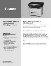
...Hi-Speed interface for improved performance** • Single Cartridge System Want a Multifunction Unit at an Affordable Price? The imageCLASS MF3110 generates fast, high quality laser documents at a fast 21 pages-per -minute (letter) • Scan up to your workspace. The 250-...-Speed interface.** An optional external print server is actually a copier, laser printer and color scanner all in one. imageCLASS® MF3110 Laser Multifunction Printer | Copier | Scanner Stylish Laser Multifunction for Your Workspace • Laser output at 1200 x 600 dpi print quality • Print and copy...
...Hi-Speed interface for improved performance** • Single Cartridge System Want a Multifunction Unit at an Affordable Price? The imageCLASS MF3110 generates fast, high quality laser documents at a fast 21 pages-per -minute (letter) • Scan up to your workspace. The 250-...-Speed interface.** An optional external print server is actually a copier, laser printer and color scanner all in one. imageCLASS® MF3110 Laser Multifunction Printer | Copier | Scanner Stylish Laser Multifunction for Your Workspace • Laser output at 1200 x 600 dpi print quality • Print and copy...
MF3110_spec.pdf
Page 2
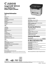
...with exchange4 Cartridge Canon X25 Cartridge (included) Ordering Information MFP and Accessories imageCLASS MF3110 9866A001AA X25 Cartridge (yields 2,500 pages based on 20 lb. All other countries. imageCLASS® MF3110 Laser Multifunction Printer | Copier | Scanner Technical Information PRINT Type Monochrome Laser Print Speed ... 48-bit (internal) / 24-bit (output) Document Size Up to change without notice. ©2004 Canon U.S.A., Inc., Canon and imageCLASS are registered trademarks of Microsoft Corporation in the United States and/or other product and brand names are trademarks...
...with exchange4 Cartridge Canon X25 Cartridge (included) Ordering Information MFP and Accessories imageCLASS MF3110 9866A001AA X25 Cartridge (yields 2,500 pages based on 20 lb. All other countries. imageCLASS® MF3110 Laser Multifunction Printer | Copier | Scanner Technical Information PRINT Type Monochrome Laser Print Speed ... 48-bit (internal) / 24-bit (output) Document Size Up to change without notice. ©2004 Canon U.S.A., Inc., Canon and imageCLASS are registered trademarks of Microsoft Corporation in the United States and/or other product and brand names are trademarks...
Service Manual
Page 7
... ...1 3 1.2.3System Requirements for Printer Driver ...1 4 1.3 Names of Parts...1 5 1.3.1External View...1 5 1.3.2Operation panel ...1 7 1.4 Safety...1 8 1.4.1Safety of Laser Light ...1 8 1.4.2Handling the Laser Unit ...1 8 1.4.3Safety of Toner ...1 9 Chapter 2ޓTECHNICAL REFERENCE 2.1 Document Feed and Exposure System...2 1 2.1.1 Overview/Configuration ...2 1 2.2 Laser Exposure ...2 2 2.2.1 Overview/Configuration ...2 2 2.3 Image Formation ...2 4 2.3.1 Overview/Configuration ...2 4 2.4 Pickup and Feed System...2 6 2.4.1 Overview/Configuration ...2 6 2.4.2 Detection Jams...
... ...1 3 1.2.3System Requirements for Printer Driver ...1 4 1.3 Names of Parts...1 5 1.3.1External View...1 5 1.3.2Operation panel ...1 7 1.4 Safety...1 8 1.4.1Safety of Laser Light ...1 8 1.4.2Handling the Laser Unit ...1 8 1.4.3Safety of Toner ...1 9 Chapter 2ޓTECHNICAL REFERENCE 2.1 Document Feed and Exposure System...2 1 2.1.1 Overview/Configuration ...2 1 2.2 Laser Exposure ...2 2 2.2.1 Overview/Configuration ...2 2 2.3 Image Formation ...2 4 2.3.1 Overview/Configuration ...2 4 2.4 Pickup and Feed System...2 6 2.4.1 Overview/Configuration ...2 6 2.4.2 Detection Jams...

Service Manual
Page 8
... Paper Delivery Sensor ...3 17 3.2 Document Feed/Exposure System ...3 21 3.2.1 Scanner Unit ...3 21 3.2.2 Scanner Cover Unit ...3 22 3.2.3 CCD Unit...3 25 3.2.4 Flatbed Motor Unit...3 28 3.3 LASER EXPOSURE SYSTEM ...3 31 3.3.1 Laser/Scanner Unit ...3 31 3.4 IMAGE FORMATION SYSTEM...3 34 3.4.1 Transfer Charging Roller ...3 34 3.5 PICKUP AND FEEDING SYSTEM...3 35 3.5.1 Cassette Pickup Roller ...3 35 3.5.2 Cassette Pickup Solenoid ...3 39...
... Paper Delivery Sensor ...3 17 3.2 Document Feed/Exposure System ...3 21 3.2.1 Scanner Unit ...3 21 3.2.2 Scanner Cover Unit ...3 22 3.2.3 CCD Unit...3 25 3.2.4 Flatbed Motor Unit...3 28 3.3 LASER EXPOSURE SYSTEM ...3 31 3.3.1 Laser/Scanner Unit ...3 31 3.4 IMAGE FORMATION SYSTEM...3 34 3.4.1 Transfer Charging Roller ...3 34 3.5 PICKUP AND FEEDING SYSTEM...3 35 3.5.1 Cassette Pickup Roller ...3 35 3.5.2 Cassette Pickup Solenoid ...3 39...

Service Manual
Page 13
%QPVGPVU Contents 1.1 Product Specifications ...1 1 1.1.1Product Specifications ...1 1 1.2 Detailed Specifications...1 3 1.2.1Printing Speed ...1 3 1.2.2Stack Upon Delivery ...1 3 1.2.3System Requirements for Printer Driver ...1 4 1.3 Names of Parts...1 5 1.3.1External View...1 5 1.3.2Operation panel ...1 7 1.4 Safety...1 8 1.4.1Safety of Laser Light ...1 8 1.4.2Handling the Laser Unit ...1 8 1.4.3Safety of Toner ...1 9
%QPVGPVU Contents 1.1 Product Specifications ...1 1 1.1.1Product Specifications ...1 1 1.2 Detailed Specifications...1 3 1.2.1Printing Speed ...1 3 1.2.2Stack Upon Delivery ...1 3 1.2.3System Requirements for Printer Driver ...1 4 1.3 Names of Parts...1 5 1.3.1External View...1 5 1.3.2Operation panel ...1 7 1.4 Safety...1 8 1.4.1Safety of Laser Light ...1 8 1.4.2Handling the Laser Unit ...1 8 1.4.3Safety of Toner ...1 9

Service Manual
Page 15
First Print Time approx. 13.8 sec. 1.1 Product Specifications 1.1.1 Product Specifications Chapter 1 0007-7055 Body installation method Desktop Exposure Method Semi conductor laser Development Method Toner projection Transfer Method Roller transfer Fixing method On demand fixing Delivery method Facedown /Faceup Toner level detection function None Toner supply type ...
First Print Time approx. 13.8 sec. 1.1 Product Specifications 1.1.1 Product Specifications Chapter 1 0007-7055 Body installation method Desktop Exposure Method Semi conductor laser Development Method Toner projection Transfer Method Roller transfer Fixing method On demand fixing Delivery method Facedown /Faceup Toner level detection function None Toner supply type ...
Service Manual
Page 22
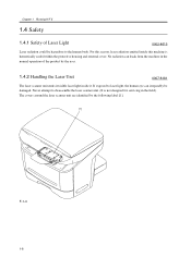
...leaak from the machine in the field). The covers around the laser scanner unit are identified by the user. 1.4.2 Handling the Laser Unit 0007-8181 The laser scanner unit emits invisible laser light inside this reason, laser radiation emitted inside it. Chapter 1ޓRunning H/F... by the following label [1]. [1] F-1-4 1-8 Never attempt to the human body. No radiation can irreparably be hazardous to disassemble the laser scanner unit. (It is hermetically sealed within the protective housing and external cover. For this machine is not designed for servicing in...
...leaak from the machine in the field). The covers around the laser scanner unit are identified by the user. 1.4.2 Handling the Laser Unit 0007-8181 The laser scanner unit emits invisible laser light inside this reason, laser radiation emitted inside it. Chapter 1ޓRunning H/F... by the following label [1]. [1] F-1-4 1-8 Never attempt to the human body. No radiation can irreparably be hazardous to disassemble the laser scanner unit. (It is hermetically sealed within the protective housing and external cover. For this machine is not designed for servicing in...
Service Manual
Page 27
%QPVGPVU Contents 2.1 Document Feed and Exposure System...2 1 2.1.1 Overview/Configuration ...2 1 2.1.1.1 Overview ...2 1 2.2 Laser Exposure ...2 2 2.2.1 Overview/Configuration ...2 2 2.2.1.1 Overview ...2 2 2.3 Image Formation ...2 4 2.3.1 Overview/Configuration ...2 4 2.3.1.1 Overview ...2 4 2.4 Pickup and Feed System...2 6 2.4.1 Overview/Configuration ...2 6 2.4.1.1 Overview ...2 6 2.4.2 Detection Jams ...2 7 2.4.2.1 Jam Detection Outline ...2 7 2.4.2.2 Delay Jams...2 8 2.4.2.3 Stationary Jams...2 8 2.4.2.4 ...
%QPVGPVU Contents 2.1 Document Feed and Exposure System...2 1 2.1.1 Overview/Configuration ...2 1 2.1.1.1 Overview ...2 1 2.2 Laser Exposure ...2 2 2.2.1 Overview/Configuration ...2 2 2.2.1.1 Overview ...2 2 2.3 Image Formation ...2 4 2.3.1 Overview/Configuration ...2 4 2.3.1.1 Overview ...2 4 2.4 Pickup and Feed System...2 6 2.4.1 Overview/Configuration ...2 6 2.4.1.1 Overview ...2 6 2.4.2 Detection Jams ...2 7 2.4.2.1 Jam Detection Outline ...2 7 2.4.2.2 Delay Jams...2 8 2.4.2.3 Stationary Jams...2 8 2.4.2.4 ...
Service Manual
Page 30
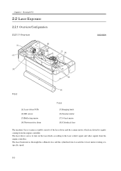
...T-2-2 [5] Imaging lends [6] Scanner motor [7] 4 facet mirror [8] Cylindrical lens The machine's laser scanner assembly consists of the laser driver and the scanner motor, which are driven by signals coming from the engine controller. The laser beam moves thorough the collimator less and the cylindrical lens to the... laser control signal and video signals from the engine controller. The laser driver serves to turn on the laser diode according to reach the 4 facet ...
...T-2-2 [5] Imaging lends [6] Scanner motor [7] 4 facet mirror [8] Cylindrical lens The machine's laser scanner assembly consists of the laser driver and the scanner motor, which are driven by signals coming from the engine controller. The laser beam moves thorough the collimator less and the cylindrical lens to the... laser control signal and video signals from the engine controller. The laser driver serves to turn on the laser diode according to reach the 4 facet ...
Service Manual
Page 31
... or a scanner fault is identified as being generated. Chapter 2 The leaser beam reflected by 120 sec; Do not attempt to accelerate. The laser/scanner unit contains parts that cannot be adjusted in front of /BDI signals, it has stopped forcing the scanner motor to reach and focus on... drum. Memo: BD Fault The machine identifies a BD fault if it does not detect the /BDI signal at a specific speed, the laser beam scans the photosensitive drum in keeping with the mirror rotation, thus drawing static images on the photosensitive drum. Scanner Fault If the machine ...
... or a scanner fault is identified as being generated. Chapter 2 The leaser beam reflected by 120 sec; Do not attempt to accelerate. The laser/scanner unit contains parts that cannot be adjusted in front of /BDI signals, it has stopped forcing the scanner motor to reach and focus on... drum. Memo: BD Fault The machine identifies a BD fault if it does not detect the /BDI signal at a specific speed, the laser beam scans the photosensitive drum in keeping with the mirror rotation, thus drawing static images on the photosensitive drum. Scanner Fault If the machine ...
Service Manual
Page 32
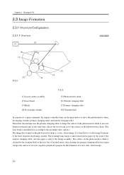
...to an even, negative potential and, at the same time, directs the laser beam across the surface of the photosensitive drum. (The laser beam is modulated to according to the incoming video signals.) The image thus.... Chapter 2ޓRunning H/F 5 2.3 Image Formation 2.3.1 Overview/Configuration 2.3.1.1 Overview [2] [1] [8] [7] 0002-8626 [6] F-2-3 [3] [4] [5] [1] Laser/scanner assembly [2] Laser beam [3] Blade [4] Developing cylinder T-2-3 [5] Photosensitive drum [6] Transfer charging roller [7] Primary charging roller [8] Cleaning blade In response to a print command, the...
...to an even, negative potential and, at the same time, directs the laser beam across the surface of the photosensitive drum. (The laser beam is modulated to according to the incoming video signals.) The image thus.... Chapter 2ޓRunning H/F 5 2.3 Image Formation 2.3.1 Overview/Configuration 2.3.1.1 Overview [2] [1] [8] [7] 0002-8626 [6] F-2-3 [3] [4] [5] [1] Laser/scanner assembly [2] Laser beam [3] Blade [4] Developing cylinder T-2-3 [5] Photosensitive drum [6] Transfer charging roller [7] Primary charging roller [8] Cleaning blade In response to a print command, the...

Service Manual
Page 35
When the laser/scanner and the fixing unit become ready for operation, the machine turns off within a specific period of time after pickup starts. Pickup Stationary Jam The ...; Delivery Delay Jam The top sensor goes on within a specific period of the feed roller so that the paper will not move forward until the laser/scanner and the fixing unit become ready for operation. Delivery Stationary Jam The delivery sensor goes on, but it does not go on , but it...
When the laser/scanner and the fixing unit become ready for operation, the machine turns off within a specific period of time after pickup starts. Pickup Stationary Jam The ...; Delivery Delay Jam The top sensor goes on within a specific period of the feed roller so that the paper will not move forward until the laser/scanner and the fixing unit become ready for operation. Delivery Stationary Jam The delivery sensor goes on, but it does not go on , but it...
Service Manual
Page 45
...the Operation Panel Unit 3 32 3.2.4.8 Removing the Scanner Cover Unit...3 32 3.2.4.9 Removing the Flatbed Motor Unit ...3 33 3.3 LASER EXPOSURE SYSTEM ...3 34 3.3.1 Laser/Scanner Unit...3 34 3.3.1.1 Removing the Cassette ...3 34 3.3.1.2 Removing the right cover ...3 34 3.3.1.3 Removing the left cover ...34 3.3.1.4 Removing the rear cover ...3 35 3.3.1.5 Removing the Scanner Unit...3 35 3.3.1.6 Removing the Top Cover ...3 35 3.3.1.7 Removing the Laser/Scanner Unit...3 36 3.4 IMAGE FORMATION SYSTEM ...3 37 3.4.1 Transfer Charging Roller ...3 37 3.4.1.1 Removing the Transfer Charging Roller 3 37 ...
...the Operation Panel Unit 3 32 3.2.4.8 Removing the Scanner Cover Unit...3 32 3.2.4.9 Removing the Flatbed Motor Unit ...3 33 3.3 LASER EXPOSURE SYSTEM ...3 34 3.3.1 Laser/Scanner Unit...3 34 3.3.1.1 Removing the Cassette ...3 34 3.3.1.2 Removing the right cover ...3 34 3.3.1.3 Removing the left cover ...34 3.3.1.4 Removing the rear cover ...3 35 3.3.1.5 Removing the Scanner Unit...3 35 3.3.1.6 Removing the Top Cover ...3 35 3.3.1.7 Removing the Laser/Scanner Unit...3 36 3.4 IMAGE FORMATION SYSTEM ...3 37 3.4.1 Transfer Charging Roller ...3 37 3.4.1.1 Removing the Transfer Charging Roller 3 37 ...
Service Manual
Page 82
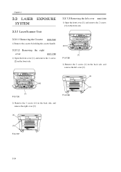
Chapter 3ޓ 3.3 LASER EXPOSURE SYSTEM 3.3.1 Laser/Scanner Unit 3.3.1.1 Removing the Cassette 0002-7542 1) Remove the cassette by holding the cassette handle. 3.3.1.2 Removing the right cover 0007-7768 1) Open the front cover [1], ...
Chapter 3ޓ 3.3 LASER EXPOSURE SYSTEM 3.3.1 Laser/Scanner Unit 3.3.1.1 Removing the Cassette 0002-7542 1) Remove the cassette by holding the cassette handle. 3.3.1.2 Removing the right cover 0007-7768 1) Open the front cover [1], ...


