Service Manual
Page 3
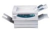
...of the ADF in view of operation. Appendix contains a general timing chart and general circuit diagrams. COPYRIGHT © 1999 CANON INC. Chapter 11 Troubleshooting provides tables of periodically replaced parts and consumables/durables and scheduled servicing charts. This service manual ...). Chapter 5 Pick-Up/Feeding System discusses the principles of parts, and how originals are made on a step-by -step instructions. Chapter 7 Externals/Auxiliary Mechanisms discusses the principles of installation, and shows how the machine may be installed using step-by -step...
...of the ADF in view of operation. Appendix contains a general timing chart and general circuit diagrams. COPYRIGHT © 1999 CANON INC. Chapter 11 Troubleshooting provides tables of periodically replaced parts and consumables/durables and scheduled servicing charts. This service manual ...). Chapter 5 Pick-Up/Feeding System discusses the principles of parts, and how originals are made on a step-by -step instructions. Chapter 7 Externals/Auxiliary Mechanisms discusses the principles of installation, and shows how the machine may be installed using step-by -step...
Service Manual
Page 11
I. Copier 1-2 B. External View 1-10 B. Control Panel 1-15 V. FEATURES 1-1 II. ADF 1-8 III. CANON PC800s/900s REV.0 AUG. 1999 PRINTED IN JAPAN (IMPRIME AU JAPON) SPECIFICATIONS 1-2 A. Cross Section 1-13 IV. Outline 1-20 COPYRIGHT © 1999 CANON INC. NAMES OF PARTS 1-10 A. IMAGE FORMATION 1-20 A. CHAPTER 1 GENERAL DESCRIPTION This chapter provides specifications of the machine, instructions on how to operate the machine, and an outline of copying process. USING THE MACHINE 1-15 A. ROUTINE MAINTENANCE BY THE USER 1-17 VI.
I. Copier 1-2 B. External View 1-10 B. Control Panel 1-15 V. FEATURES 1-1 II. ADF 1-8 III. CANON PC800s/900s REV.0 AUG. 1999 PRINTED IN JAPAN (IMPRIME AU JAPON) SPECIFICATIONS 1-2 A. Cross Section 1-13 IV. Outline 1-20 COPYRIGHT © 1999 CANON INC. NAMES OF PARTS 1-10 A. IMAGE FORMATION 1-20 A. CHAPTER 1 GENERAL DESCRIPTION This chapter provides specifications of the machine, instructions on how to operate the machine, and an outline of copying process. USING THE MACHINE 1-15 A. ROUTINE MAINTENANCE BY THE USER 1-17 VI.
Service Manual
Page 29
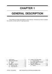
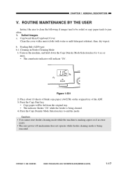
... the cover with a moist cloth (with water or mild detergent solution); Soiled Images a. b. COPYRIGHT © 1999 CANON INC. CANON PC800s/900s REV.0 AUG. 1999 PRINTED IN JAPAN (IMPRIME AU JAPON) 1-17 ROUTINE MAINTENANCE BY THE USER Instruct the user to clean the following if images tend to be fed from the original tray...
... the cover with a moist cloth (with water or mild detergent solution); Soiled Images a. b. COPYRIGHT © 1999 CANON INC. CANON PC800s/900s REV.0 AUG. 1999 PRINTED IN JAPAN (IMPRIME AU JAPON) 1-17 ROUTINE MAINTENANCE BY THE USER Instruct the user to clean the following if images tend to be fed from the original tray...
Service Manual
Page 38
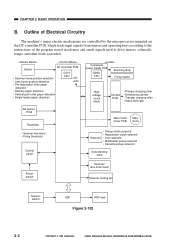
...switch Scanner/ lens drive motor Scanner cooling fan Sensor/ switch ADF ADF load Figure 2-102 2-2 COPYRIGHT © 1999 CANON INC. CANON PC800s/900s REV.0 AUG. 1999 PRINTED IN JAPAN (IMPRIME AU JAPON) CHAPTER 2 BASIC OPERATION B. Outline of Electrical... Circuitry The machine's major electric mechanisms are controlled by the microprocessor mounted on the DC controller PCB, which reads input signals from sensors and operating keys according to the instructions...
...switch Scanner/ lens drive motor Scanner cooling fan Sensor/ switch ADF ADF load Figure 2-102 2-2 COPYRIGHT © 1999 CANON INC. CANON PC800s/900s REV.0 AUG. 1999 PRINTED IN JAPAN (IMPRIME AU JAPON) CHAPTER 2 BASIC OPERATION B. Outline of Electrical... Circuitry The machine's major electric mechanisms are controlled by the microprocessor mounted on the DC controller PCB, which reads input signals from sensors and operating keys according to the instructions...

Service Manual
Page 58
.../Lens Drive Motor If overcurrent flows to the scanner/lens drive motor for some reason, the fuse (R339) on the DC controller PCB receives instructions from 1 to 3 generated by the microprocessor (Q101) are used to control the current flowing to the motor so that it varies according to...is switched on and off by the microprocessor (Q101). Any of drive pulses (SC-A*through SC-B*). In response, it has blown. 3-8 COPYRIGHT © 1999 CANON INC. Caution: The fuse (R339) will blow to cut the power to the scanner/lens drive motor (M2) through B*) generated by pulse signals (A ...
.../Lens Drive Motor If overcurrent flows to the scanner/lens drive motor for some reason, the fuse (R339) on the DC controller PCB receives instructions from 1 to 3 generated by the microprocessor (Q101) are used to control the current flowing to the motor so that it varies according to...is switched on and off by the microprocessor (Q101). Any of drive pulses (SC-A*through SC-B*). In response, it has blown. 3-8 COPYRIGHT © 1999 CANON INC. Caution: The fuse (R339) will blow to cut the power to the scanner/lens drive motor (M2) through B*) generated by pulse signals (A ...

Service Manual
Page 62
As a rule, do not operate the machine with wider thread intervals). CANON PC800s/900s REV.0 AUG. 1999 PRINTED IN JAPAN (IMPRIME AU JAPON) Unless otherwise instructed, assemble the parts by type (length, diameter) and location. 4. A few of its part removed. 7. Use the washers where necessary....3 EXPOSURE SYSTEM III. Identify the screws by reversing the steps used are special screws (with any screws indiscriminately. 3-12 COPYRIGHT © 1999 CANON INC. Before starting the work, turn off the power switch and disconnect the power plug for safety. 2. Do not use any of the ...
As a rule, do not operate the machine with wider thread intervals). CANON PC800s/900s REV.0 AUG. 1999 PRINTED IN JAPAN (IMPRIME AU JAPON) Unless otherwise instructed, assemble the parts by type (length, diameter) and location. 4. A few of its part removed. 7. Use the washers where necessary....3 EXPOSURE SYSTEM III. Identify the screws by reversing the steps used are special screws (with any screws indiscriminately. 3-12 COPYRIGHT © 1999 CANON INC. Before starting the work, turn off the power switch and disconnect the power plug for safety. 2. Do not use any of the ...

Service Manual
Page 116
... wire and Varis- tors come with wider thread intervals). As a rule, do not operate the machine with the following in mind: 1. ! CANON PC800s/900s REV.0 AUG. 1999 PRINTED IN JAPAN (IMPRIME AU JAPON) CHAPTER 4 IMAGE FORMATION SYSTEM II. Before starting the work, turn off... the power switch and disconnect the power plug for safety. 2. Unless otherwise instructed, assemble the parts by type (length, diameter) and location. 4. Use the washers where necessary. (The screws used to ensure electrical continuity.) ...
... wire and Varis- tors come with wider thread intervals). As a rule, do not operate the machine with the following in mind: 1. ! CANON PC800s/900s REV.0 AUG. 1999 PRINTED IN JAPAN (IMPRIME AU JAPON) CHAPTER 4 IMAGE FORMATION SYSTEM II. Before starting the work, turn off... the power switch and disconnect the power plug for safety. 2. Unless otherwise instructed, assemble the parts by type (length, diameter) and location. 4. Use the washers where necessary. (The screws used to ensure electrical continuity.) ...

Service Manual
Page 142
... needed, disassemble/assemble the machine with any screws indiscriminately. 5-18 COPYRIGHT © 1999 CANON INC. Identify the screws by reversing the steps used to ensure electrical continuity.) 5. Unless otherwise instructed, assemble the parts by type (length, diameter) and location. 4. CANON PC800s/900s REV.0 AUG. 1999 PRINTED IN JAPAN (IMPRIME AU JAPON) As necessary...
... needed, disassemble/assemble the machine with any screws indiscriminately. 5-18 COPYRIGHT © 1999 CANON INC. Identify the screws by reversing the steps used to ensure electrical continuity.) 5. Unless otherwise instructed, assemble the parts by type (length, diameter) and location. 4. CANON PC800s/900s REV.0 AUG. 1999 PRINTED IN JAPAN (IMPRIME AU JAPON) As necessary...
Service Manual
Page 174
...where necessary. (The screws used are special screws (with any screws indiscriminately. 6-10 COPYRIGHT © 1999 CANON INC. A few of its part removed. 7. CANON PC800s/900s REV.0 AUG. 1999 PRINTED IN JAPAN (IMPRIME AU JAPON) Identify the screws by reversing the ...steps used to disassemble it. 3. As a rule, do not operate the machine with wider thread intervals). Do not use any of the screws used to ensure electrical continuity.) 5. Unless otherwise instructed...
...where necessary. (The screws used are special screws (with any screws indiscriminately. 6-10 COPYRIGHT © 1999 CANON INC. A few of its part removed. 7. CANON PC800s/900s REV.0 AUG. 1999 PRINTED IN JAPAN (IMPRIME AU JAPON) Identify the screws by reversing the ...steps used to disassemble it. 3. As a rule, do not operate the machine with wider thread intervals). Do not use any of the screws used to ensure electrical continuity.) 5. Unless otherwise instructed...
Service Manual
Page 187
... the machine with wider thread intervals). A few of its part removed. 7. CANON PC800s/900s REV.0 AUG. 1999 PRINTED IN JAPAN (IMPRIME AU JAPON) 7-7 Do not use any of the screws used are special screws (with any screws indiscriminately. Unless otherwise instructed, assemble the parts by type (length, diameter) and location. 4. As necessary...
... the machine with wider thread intervals). A few of its part removed. 7. CANON PC800s/900s REV.0 AUG. 1999 PRINTED IN JAPAN (IMPRIME AU JAPON) 7-7 Do not use any of the screws used are special screws (with any screws indiscriminately. Unless otherwise instructed, assemble the parts by type (length, diameter) and location. 4. As necessary...
Service Manual
Page 188
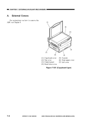
CHAPTER 7 EXTERNALS/AUXILIARY MECHANISMS A. CANON PC800s/900s REV.0 AUG. 1999 PRINTED IN JAPAN (IMPRIME AU JAPON) External Covers For instructions on how to remove the ADF, see Chapter 8. [1] [2] [3] [4] [7] [6] [1] Copyboard cover [2] Top cover [3] Control panel [4] Front lower cover [5] [5] Cassette [6] Front upper cover [7] Left cover Figure 7-301 (Copyboard type) 7-8 COPYRIGHT © 1999 CANON INC.
CHAPTER 7 EXTERNALS/AUXILIARY MECHANISMS A. CANON PC800s/900s REV.0 AUG. 1999 PRINTED IN JAPAN (IMPRIME AU JAPON) External Covers For instructions on how to remove the ADF, see Chapter 8. [1] [2] [3] [4] [7] [6] [1] Copyboard cover [2] Top cover [3] Control panel [4] Front lower cover [5] [5] Cassette [6] Front upper cover [7] Left cover Figure 7-301 (Copyboard type) 7-8 COPYRIGHT © 1999 CANON INC.

Service Manual
Page 224
...rule, do not operate the machine with a washer to ensure electrical continuity.) 5. tors come with any screws indiscriminately. 8-18 COPYRIGHT © 1999 CANON INC. A few of its part removed. 7. Identify the screws by reversing the steps used to disassemble it. 3. CHAPTER 8 ADF II. Do ...not use any of the screws used are special screws (with the following in mind: 1. ! Unless otherwise instructed, assemble the parts by type (length, diameter) and location. 4. DISASSEMBLY/ASSEMBLY As needed, disassemble/assemble the machine with wider thread intervals). ...
...rule, do not operate the machine with a washer to ensure electrical continuity.) 5. tors come with any screws indiscriminately. 8-18 COPYRIGHT © 1999 CANON INC. A few of its part removed. 7. Identify the screws by reversing the steps used to disassemble it. 3. CHAPTER 8 ADF II. Do ...not use any of the screws used are special screws (with the following in mind: 1. ! Unless otherwise instructed, assemble the parts by type (length, diameter) and location. 4. DISASSEMBLY/ASSEMBLY As needed, disassemble/assemble the machine with wider thread intervals). ...
Service Manual
Page 266
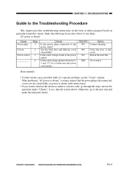
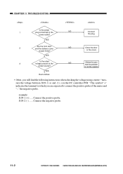
...or the cover. If the problem is "AC power is absent," you may suspect that Go to the power outlet? COPYRIGHT © 1999 CANON INC. Is the rated voltage present between J11 and -2? (J1 is disconnected, covers are not closed fully? Inform the user that the power.... Otherwise, go through the steps: answer the questions under "Checks"; CHAPTER 11 TROUBLESHOOTING Guide to the Troubleshooting Procedure This chapter provides troubleshooting instructions in the form of tables prepared based on generally found near the power cord mount.) YES/NO NO NO NO YES Action Connect the ...
...or the cover. If the problem is "AC power is absent," you may suspect that Go to the power outlet? COPYRIGHT © 1999 CANON INC. Is the rated voltage present between J11 and -2? (J1 is disconnected, covers are not closed fully? Inform the user that the power.... Otherwise, go through the steps: answer the questions under "Checks"; CHAPTER 11 TROUBLESHOOTING Guide to the Troubleshooting Procedure This chapter provides troubleshooting instructions in the form of tables prepared based on generally found near the power cord mount.) YES/NO NO NO NO YES Action Connect the ...
Service Manual
Page 267
...The symbol "+" indicates the terminal to which you will find the following instructions when checking the voltage using a meter: "measure the voltage between J109-1 (+) and -2 (-) on the DC controller PCB." example: J109-1 (+) ..... CANON PC800s/900s REV.0 AUG. 1999 PRINTED IN JAPAN (IMPRIME AU JAPON)...Often, you are expected to the NO power outlet? is not the copier's. Connect the negative probe. 11-2 COPYRIGHT © 1999 CANON INC. CHAPTER 11 TROUBLESHOOTING Is the power 1 plug connected to connect the positive probe of the meter and "-," the negative probe. ...
...The symbol "+" indicates the terminal to which you will find the following instructions when checking the voltage using a meter: "measure the voltage between J109-1 (+) and -2 (-) on the DC controller PCB." example: J109-1 (+) ..... CANON PC800s/900s REV.0 AUG. 1999 PRINTED IN JAPAN (IMPRIME AU JAPON)...Often, you are expected to the NO power outlet? is not the copier's. Connect the negative probe. 11-2 COPYRIGHT © 1999 CANON INC. CHAPTER 11 TROUBLESHOOTING Is the power 1 plug connected to connect the positive probe of the meter and "-," the negative probe. ...
Service Manual
Page 312
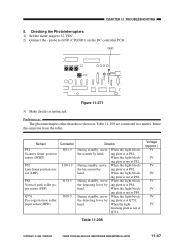
...lens mount by hand. CANON PC800s/900s REV.0 AUG. 1999 PRINTED IN JAPAN (IMPRIME AU JAPON) 11-47 probe to 12 VDC. 2) Connect the - During standby, move the detecting lever by hand. GND VR104 VR105 VR106 VR107 CP23 CPGND1 Figure 11-271 3) Make checks as instructed. Reference: The photointerrupers...When the lightblocking plate is not at Q751, Voltage (approx.) 5V 0V 5V 0V 5V 0V 0V 5V Table 11-208 COPYRIGHT © 1999 CANON INC. Checking the Photointerrupters 1) Set the meter range to GND (CPGND1) on the DC controller PCB. Sensor Connector Checks PS1 Scanner home position ...
...lens mount by hand. CANON PC800s/900s REV.0 AUG. 1999 PRINTED IN JAPAN (IMPRIME AU JAPON) 11-47 probe to 12 VDC. 2) Connect the - During standby, move the detecting lever by hand. GND VR104 VR105 VR106 VR107 CP23 CPGND1 Figure 11-271 3) Make checks as instructed. Reference: The photointerrupers...When the lightblocking plate is not at Q751, Voltage (approx.) 5V 0V 5V 0V 5V 0V 0V 5V Table 11-208 COPYRIGHT © 1999 CANON INC. Checking the Photointerrupters 1) Set the meter range to GND (CPGND1) on the DC controller PCB. Sensor Connector Checks PS1 Scanner home position ...
Service Manual
Page 313
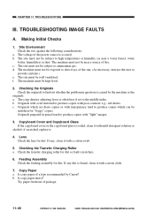
... it with a moist cloth. 7. Is copy paper moist? Originals prepared in question is as near a source of the sun. (As necessary, instruct the user to find out whether the problem in pencil tend to produce copies with "light" images. 3. Checking the Transfer Charging Roller a. If ...Is copy paper of a type recommended by the machine or the originals. Try paper fresh out of the power source is caused by Canon? TROUBLESHOOTING IMAGE FAULTS A. Site Environment Check the site against the following considerations: a. The machine must be mistaken for dirt. The machine ...
... it with a moist cloth. 7. Is copy paper moist? Originals prepared in question is as near a source of the sun. (As necessary, instruct the user to find out whether the problem in pencil tend to produce copies with "light" images. 3. Checking the Transfer Charging Roller a. If ...Is copy paper of a type recommended by the machine or the originals. Try paper fresh out of the power source is caused by Canon? TROUBLESHOOTING IMAGE FAULTS A. Site Environment Check the site against the following considerations: a. The machine must be mistaken for dirt. The machine ...
Service Manual
Page 315
... feed assembly will cause dark images. The cartridge can occur inside it has been brought from a cold place (e.g., warehouse) to various problems; Instruct the user so that the cartridge is brought in the pickup/feeding assembly tends to two hours). 11-50 COPYRIGHT © 1999... CANON INC. tion can develop condensation if it is opened before it has become used to the room temperature (one to cause feeding faults. CANON PC800s/900s REV.0 AUG. 1999 PRINTED IN JAPAN (IMPRIME AU JAPON) c. ...
... feed assembly will cause dark images. The cartridge can occur inside it has been brought from a cold place (e.g., warehouse) to various problems; Instruct the user so that the cartridge is brought in the pickup/feeding assembly tends to two hours). 11-50 COPYRIGHT © 1999... CANON INC. tion can develop condensation if it is opened before it has become used to the room temperature (one to cause feeding faults. CANON PC800s/900s REV.0 AUG. 1999 PRINTED IN JAPAN (IMPRIME AU JAPON) c. ...
Service Manual
Page 318
...Measure the electrical resistance on the correct method of the fixing assembly. YES/NO YES NO NO YES YES NO YES NO Action End. Instruct the user on the transfer lower guide plate and the side plate (metal) of storage. 2. Inform the user that using non-recommended paper... may be in contact with a metal part (side plate). 2. COPYRIGHT © 1999 CANON INC. Replace the electric unit (composite power supply PCB, DC controller PCB). Mount the transfer charging roller correctly. 2. CANON PC800s/900s REV.0 AUG. 1999 PRINTED IN JAPAN (IMPRIME AU JAPON) 11-53 Replace ...
...Measure the electrical resistance on the correct method of the fixing assembly. YES/NO YES NO NO YES YES NO YES NO Action End. Instruct the user on the transfer lower guide plate and the side plate (metal) of storage. 2. Inform the user that using non-recommended paper... may be in contact with a metal part (side plate). 2. COPYRIGHT © 1999 CANON INC. Replace the electric unit (composite power supply PCB, DC controller PCB). Mount the transfer charging roller correctly. 2. CANON PC800s/900s REV.0 AUG. 1999 PRINTED IN JAPAN (IMPRIME AU JAPON) 11-53 Replace ...

Service Manual
Page 321
... soiled? Scanning lamp, Developing bias YES/NO YES YES Yes NO Action Try a recommend type. Instruct the user on all copies? Clean the pickup guide assembly and the delivery roller. 11-56 COPYRIGHT © 1999 CANON INC. CANON PC800s/900s REV.0 AUG. 1999 PRINTED IN JAPAN (IMPRIME AU JAPON) Check the varistor. 4. Check...
... soiled? Scanning lamp, Developing bias YES/NO YES YES Yes NO Action Try a recommend type. Instruct the user on all copies? Clean the pickup guide assembly and the delivery roller. 11-56 COPYRIGHT © 1999 CANON INC. CANON PC800s/900s REV.0 AUG. 1999 PRINTED IN JAPAN (IMPRIME AU JAPON) Check the varistor. 4. Check...

Service Manual
Page 322
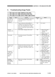
...the fixing film and the fixing lower roller for scratches. YES/NO NO Action Check the pickup roller, pickup clutch, and cassette. normal? (See the instructions on when the Copy Start key is likely to use a recommended type. to use a recommended type. Check the DC control PCB. Cause Copy paper Fixing... Step 1 2 3 Checks Is the copy paper of lines? If there are good, ask the user to be too low. YES Check the registration clutch. CANON PC800s/900s REV.0 AUG. 1999 PRINTED IN JAPAN (IMPRIME AU JAPON) 11-57 Does the heater turn on." COPYRIGHT © 1999...
...the fixing film and the fixing lower roller for scratches. YES/NO NO Action Check the pickup roller, pickup clutch, and cassette. normal? (See the instructions on when the Copy Start key is likely to use a recommended type. to use a recommended type. Check the DC control PCB. Cause Copy paper Fixing... Step 1 2 3 Checks Is the copy paper of lines? If there are good, ask the user to be too low. YES Check the registration clutch. CANON PC800s/900s REV.0 AUG. 1999 PRINTED IN JAPAN (IMPRIME AU JAPON) 11-57 Does the heater turn on." COPYRIGHT © 1999...

