Service Manual
Page 3
... be disassembled/assembled and adjusted. Chapter 6 Fixing System discusses the principles of operation. Chapter 10 Maintenance and Servicing provides tables of maintenance/inspection, standards/ adjustments, and problem identification (image fault/malfunction). Chapter 11 Troubleshooting provides tables of periodically replaced parts and consumables/durables and scheduled servicing charts. Chapter 8 ADF explains the principles of operation of the ADF in view of electrical and mechanical functions and in the...
... be disassembled/assembled and adjusted. Chapter 6 Fixing System discusses the principles of operation. Chapter 10 Maintenance and Servicing provides tables of maintenance/inspection, standards/ adjustments, and problem identification (image fault/malfunction). Chapter 11 Troubleshooting provides tables of periodically replaced parts and consumables/durables and scheduled servicing charts. Chapter 8 ADF explains the principles of operation of the ADF in view of electrical and mechanical functions and in the...
Service Manual
Page 4
... "turn on the power" means flipping on the power switch, closing the front door, and closing the delivery unit door, which results in the machine. The descriptions in this Service Manual are subject to change without notice for product improvement or other reasons, and major changes will be checked in the form of the electric sig- CANON PC800s/900s REV.0 AUG. 1999 PRINTED...
... "turn on the power" means flipping on the power switch, closing the front door, and closing the delivery unit door, which results in the machine. The descriptions in this Service Manual are subject to change without notice for product improvement or other reasons, and major changes will be checked in the form of the electric sig- CANON PC800s/900s REV.0 AUG. 1999 PRINTED...
Service Manual
Page 13
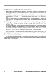
...), enabling speedy copying work . 6. multifeeder type). 7. The user may contain as many as a business card. 5. Ecology-Conscious • The use of paper (500-sheet cassette + multifeeder; Various Paper Sizes • The paper may be between 70% and 141% in a considerable reduction of ozone: 0.01 ppm or less on . 4. ADF Type • Continuous copying is 0 sec (at maximum (1/100 to make jam removal easy. 8. Separate top unit • The machine's top unit...
...), enabling speedy copying work . 6. multifeeder type). 7. The user may contain as many as a business card. 5. Ecology-Conscious • The use of paper (500-sheet cassette + multifeeder; Various Paper Sizes • The paper may be between 70% and 141% in a considerable reduction of ozone: 0.01 ppm or less on . 4. ADF Type • Continuous copying is 0 sec (at maximum (1/100 to make jam removal easy. 8. Separate top unit • The machine's top unit...
Service Manual
Page 217
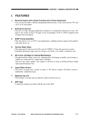
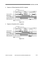
CANON PC800s/900s REV.0 AUG. 1999 PRINTED IN JAPAN (IMPRIME AU JAPON) 8-11 Sequence of Operations (LGL, 2 originals) Copying Feeding 2 Picking up 2nd original Pickup motor (M2) Belt motor (M1) Original detection sensor (PI3) Registration sensor (PI2) Delivery sensor (PI1) Original set Copy Start key ON Preparing for Picking up pickup /separating Arching Pickig up Feeding 1 Preparing for pickup of 2nd...
CANON PC800s/900s REV.0 AUG. 1999 PRINTED IN JAPAN (IMPRIME AU JAPON) 8-11 Sequence of Operations (LGL, 2 originals) Copying Feeding 2 Picking up 2nd original Pickup motor (M2) Belt motor (M1) Original detection sensor (PI3) Registration sensor (PI2) Delivery sensor (PI1) Original set Copy Start key ON Preparing for Picking up pickup /separating Arching Pickig up Feeding 1 Preparing for pickup of 2nd...
Service Manual
Page 258
COPYRIGHT © 1999 CANON INC. II. CANON PC800s/900s REV.0 AUG. 1999 PRINTED IN JAPAN (IMPRIME AU JAPON) 10-1 SCHEDULED SERVICING The machine does not have items designated as durables or consumables. DURABLES AND CONSUMABLES The machine does not have any parts which must be replaced on a periodical basis. CHAPTER 10 MAINTENANCE AND SERVICING I. III. PERIODICALLY REPLACED PARTS The machine does not have parts which require scheduled servicing.
COPYRIGHT © 1999 CANON INC. II. CANON PC800s/900s REV.0 AUG. 1999 PRINTED IN JAPAN (IMPRIME AU JAPON) 10-1 SCHEDULED SERVICING The machine does not have items designated as durables or consumables. DURABLES AND CONSUMABLES The machine does not have any parts which must be replaced on a periodical basis. CHAPTER 10 MAINTENANCE AND SERVICING I. III. PERIODICALLY REPLACED PARTS The machine does not have parts which require scheduled servicing.
Service Manual
Page 268
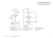
... controller PCB 5. Applies only if the machine is not equipped with a copy density correction switch (SW101). 2. Scanning system, pickup/feeding system, delivery assembly NO Is the copy density correction switch (SW101) set the copy density adjusting lever to correct image faults. Cartridge 2. Scanning lamp 3. See p. 11-42. COPYRIGHT © 1999 CANON INC. Note 2) 4. Making Pre-Checks Clean the parts. Fogging of gray scale No. 1 (good or bad; Image Adjustment Basic Procedure Adjusting...
... controller PCB 5. Applies only if the machine is not equipped with a copy density correction switch (SW101). 2. Scanning system, pickup/feeding system, delivery assembly NO Is the copy density correction switch (SW101) set the copy density adjusting lever to correct image faults. Cartridge 2. Scanning lamp 3. See p. 11-42. COPYRIGHT © 1999 CANON INC. Note 2) 4. Making Pre-Checks Clean the parts. Fogging of gray scale No. 1 (good or bad; Image Adjustment Basic Procedure Adjusting...
Service Manual
Page 313
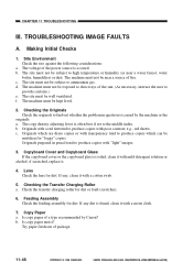
... a type recommended by the machine or the originals. d. a. Originals with a red tint tend to produce copies with transparency tend to produce copies which are diazo copies or with "light" images. 3. Is copy paper of the sun. (As necessary, instruct the user to ammonium gas. CHAPTER 11 TROUBLESHOOTING III. TROUBLESHOOTING IMAGE FAULTS A. Making Initial Checks 1. The voltage of package. 11-48 COPYRIGHT © 1999 CANON INC. b. c. The machine must...
... a type recommended by the machine or the originals. d. a. Originals with a red tint tend to produce copies with transparency tend to produce copies which are diazo copies or with "light" images. 3. Is copy paper of the sun. (As necessary, instruct the user to ammonium gas. CHAPTER 11 TROUBLESHOOTING III. TROUBLESHOOTING IMAGE FAULTS A. Making Initial Checks 1. The voltage of package. 11-48 COPYRIGHT © 1999 CANON INC. b. c. The machine must...
Service Manual
Page 318
... using non-recommended paper may be in the middle of storage. 2. End. Instruct the user on the transfer lower guide plate and the side plate (metal) of the fixing assembly. COPYRIGHT © 1999 CANON INC. Is the problem corrected? Turn off the power in contact with a metal part (side plate). 2. Measure the electrical resistance on the correct method of a copying run, and open the machine's top unit. CANON...
... using non-recommended paper may be in the middle of storage. 2. End. Instruct the user on the transfer lower guide plate and the side plate (metal) of the fixing assembly. COPYRIGHT © 1999 CANON INC. Is the problem corrected? Turn off the power in contact with a metal part (side plate). 2. Measure the electrical resistance on the correct method of a copying run, and open the machine's top unit. CANON...
Service Manual
Page 319
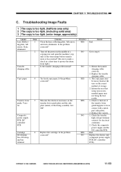
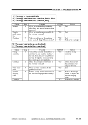
.... Replace the cartridge. 2. YES 1. CANON PC800s/900s REV.0 AUG. 1999 PRINTED IN JAPAN (IMPRIME AU JAPON) CHAPTER 11 TROUBLESHOOTING 4 The copy has uneven density. (darker at front) 5 The copy has uneven density. (lighter at front) Cause Scanner Cartridge, Scanning lamp Transfer charging roller Step 1 2 Checks Clean the scanning lamp, reflecting plate, lens, and mirror. If the image is still foggy, to the middle setting, and make a copy...
.... Replace the cartridge. 2. YES 1. CANON PC800s/900s REV.0 AUG. 1999 PRINTED IN JAPAN (IMPRIME AU JAPON) CHAPTER 11 TROUBLESHOOTING 4 The copy has uneven density. (darker at front) 5 The copy has uneven density. (lighter at front) Cause Scanner Cartridge, Scanning lamp Transfer charging roller Step 1 2 Checks Clean the scanning lamp, reflecting plate, lens, and mirror. If the image is still foggy, to the middle setting, and make a copy...
Service Manual
Page 320
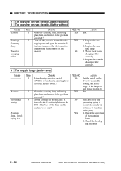
.... Does the copy image before moving through the fixing assembly have white spots or white lines? Clean the transfer guide assembly. CHAPTER 11 TROUBLESHOOTING 7 The copy is running out of a copying run, and open the machine's top unit. CANON PC800s/900s REV.0 AUG. 1999 PRINTED IN JAPAN (IMPRIME AU JAPON) 11-55 YES/NO Action YES End. YES End. Shake the cartridge several times. Is the problem corrected? 4 Is...
.... Does the copy image before moving through the fixing assembly have white spots or white lines? Clean the transfer guide assembly. CHAPTER 11 TROUBLESHOOTING 7 The copy is running out of a copying run, and open the machine's top unit. CANON PC800s/900s REV.0 AUG. 1999 PRINTED IN JAPAN (IMPRIME AU JAPON) 11-55 YES/NO Action YES End. YES End. Shake the cartridge several times. Is the problem corrected? 4 Is...
Service Manual
Page 324
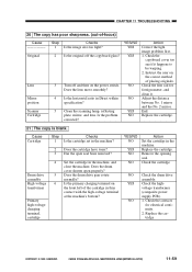
... copy is blank. Adjust the distance between No. 1 mirror and the No. 2 mirror. Check the cartridge. NO 1. CANON PC800s/900s REV.0 AUG. 1999 PRINTED IN JAPAN (IMPRIME AU JAPON) 11-59 Does the lens move smoothly? Instruct the user on the power switch. Check the copyboard cover too see if it . Remove the opening seal. Does the drum drive gear rotate normally? Does the cartridge have toner? CHAPTER 11 TROUBLESHOOTING...
... copy is blank. Adjust the distance between No. 1 mirror and the No. 2 mirror. Check the cartridge. NO 1. CANON PC800s/900s REV.0 AUG. 1999 PRINTED IN JAPAN (IMPRIME AU JAPON) 11-59 Does the lens move smoothly? Instruct the user on the power switch. Check the copyboard cover too see if it . Remove the opening seal. Does the drum drive gear rotate normally? Does the cartridge have toner? CHAPTER 11 TROUBLESHOOTING...
Service Manual
Page 330
... "The lens fails to turn on ? NO Replace the DC controller PCB. 10 E240 Cause Wiring Composite power supply PCB DC controller PCB Step 1 2 Checks Is the wiring from J109 on ." YES/NO NO YES Action See "The scanning lamp fails to move when the power is turned on when the Copy Start key is pressed? CANON PC800s/900s REV.0 AUG. 1999 PRINTED IN JAPAN (IMPRIME...
... "The lens fails to turn on ? NO Replace the DC controller PCB. 10 E240 Cause Wiring Composite power supply PCB DC controller PCB Step 1 2 Checks Is the wiring from J109 on ." YES/NO NO YES Action See "The scanning lamp fails to move when the power is turned on when the Copy Start key is pressed? CANON PC800s/900s REV.0 AUG. 1999 PRINTED IN JAPAN (IMPRIME...

Service Manual
Page 332
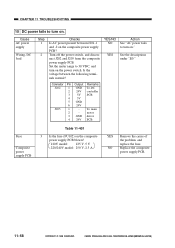
... the DC controller PCB? Remove the cause, and replace the fuse. Cause Power plug Machine top unit Power supply Fuse (FU501) Fuse (FU102) Door switch (DS1) Noise filter PCB Harness Connector connection 1 Connector connection 2 Control panel PCB Composite power supply PCB Step 1 2 3 4 5 6 7 8 9 10 11 12 Checks Is the power plug connected to F1 and F3 or F2 and F4 of the faston of the problem, and replace the...
... the DC controller PCB? Remove the cause, and replace the fuse. Cause Power plug Machine top unit Power supply Fuse (FU501) Fuse (FU102) Door switch (DS1) Noise filter PCB Harness Connector connection 1 Connector connection 2 Control panel PCB Composite power supply PCB Step 1 2 3 4 5 6 7 8 9 10 11 12 Checks Is the power plug connected to F1 and F3 or F2 and F4 of the faston of the problem, and replace the...
Service Manual
Page 333
... NO YES Connector Pin Output Remarks J202 1 GND To DC 2 24V controller 3 5V PCB 4 5V 5 GND 6 24V J205 1 - motor 3 GND driver 4 24V PCB Action See "AC power fails to turn on the power switch. Turn off the power switch, and disconnect J202 and J205 from the composite power supply PCB. Cause AC power supply Wiring, DC load Step 1 2 Checks Is AC power present between the following...
... NO YES Connector Pin Output Remarks J202 1 GND To DC 2 24V controller 3 5V PCB 4 5V 5 GND 6 24V J205 1 - motor 3 GND driver 4 24V PCB Action See "AC power fails to turn on the power switch. Turn off the power switch, and disconnect J202 and J205 from the composite power supply PCB. Cause AC power supply Wiring, DC load Step 1 2 Checks Is AC power present between the following...
Service Manual
Page 335
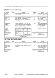
... machine. CANON PC800s/900s REV.0 AUG. 1999 PRINTED IN JAPAN (IMPRIME AU JAPON) Does the main motor (M1) rotate when the Copy Start key is pressed? See "The main motor fails to PS5 on the control panel? Is the single-feeder paper sensor (PS5) normal? if normal, replace PS5. Instruct the user on the correct way of placing paper. Replace the DC controller PCB. 18 Pickup fails. (single-feeder...
... machine. CANON PC800s/900s REV.0 AUG. 1999 PRINTED IN JAPAN (IMPRIME AU JAPON) Does the main motor (M1) rotate when the Copy Start key is pressed? See "The main motor fails to PS5 on the control panel? Is the single-feeder paper sensor (PS5) normal? if normal, replace PS5. Instruct the user on the correct way of placing paper. Replace the DC controller PCB. 18 Pickup fails. (single-feeder...
Service Manual
Page 336
... voltage between J109-6 (+) and -5 (-) on for a moment after the Copy Start key is pressed? if normal, replace Q751. CANON PC800s/900s REV.0 AUG. 1999 PRINTED IN JAPAN (IMPRIME AU JAPON) 11-71 Move the scanner by hand. See "DC power fails to turn on the DC controller PCB change to about 24 V? Check the wiring from J108 on ." Cause Main motor (M1) Pre...
... voltage between J109-6 (+) and -5 (-) on for a moment after the Copy Start key is pressed? if normal, replace Q751. CANON PC800s/900s REV.0 AUG. 1999 PRINTED IN JAPAN (IMPRIME AU JAPON) 11-71 Move the scanner by hand. See "DC power fails to turn on the DC controller PCB change to about 24 V? Check the wiring from J108 on ." Cause Main motor (M1) Pre...
Service Manual
Page 337
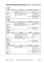
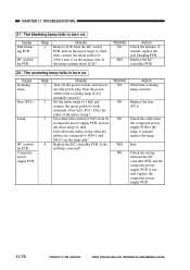
...;; CANON PC800s/900s REV.0 AUG. 1999 PRINTED IN JAPAN (IMPRIME AU JAPON) Disconnect the connector J910 from the composite power supply PCB to the lamp; Replace the DC controller PCB. YES/NO Action NO Mount the scanning lamp correctly. NO Replace the fuse (FU1). CHAPTER 11 TROUBLESHOOTING 21 The blanking lamp fails to turn on. Cause Side blanking PCB DC controller PCB Step 1 Checks Remove J106...
...;; CANON PC800s/900s REV.0 AUG. 1999 PRINTED IN JAPAN (IMPRIME AU JAPON) Disconnect the connector J910 from the composite power supply PCB to the lamp; Replace the DC controller PCB. YES/NO Action NO Mount the scanning lamp correctly. NO Replace the fuse (FU1). CHAPTER 11 TROUBLESHOOTING 21 The blanking lamp fails to turn on. Cause Side blanking PCB DC controller PCB Step 1 Checks Remove J106...

Service Manual
Page 338
... DC controller PCB to turn on when the power switch is turned on the composite power supply PCB. Cause Lens solenoid (SL3) Step 1 Checks Does the lens solenoid (SL3) turn on ." DC power supply Scanner/lens drive motor (M2) DC control PCB 3 Set the meter range to the 30 VDC, and connect J202-2 (+) and -1 (-) on ? as necessary, clean the cable and adjust its tension. Is the problem corrected...
... DC controller PCB to turn on when the power switch is turned on the composite power supply PCB. Cause Lens solenoid (SL3) Step 1 Checks Does the lens solenoid (SL3) turn on ." DC power supply Scanner/lens drive motor (M2) DC control PCB 3 Set the meter range to the 30 VDC, and connect J202-2 (+) and -1 (-) on ? as necessary, clean the cable and adjust its tension. Is the problem corrected...
Service Manual
Page 339
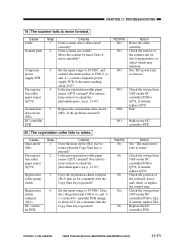
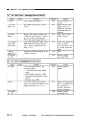
... necessary, clean the cable and adjust its tension. NO Replace the DC controller PCB. 26 The "Jam" message fails to turn off . if normal, replace the sensor in step 1 normal? (For instructions on how to check the photointerrupers, see p. 11-47.) Replace the control panel PCB. CHAPTER 11 TROUBLESHOOTING 25 The "Add Paper" message fails to turn off . Is the problem corrected? NO Check the wiring from the DC controller PCB to check the photointerrupters...
... necessary, clean the cable and adjust its tension. NO Replace the DC controller PCB. 26 The "Jam" message fails to turn off . if normal, replace the sensor in step 1 normal? (For instructions on how to check the photointerrupers, see p. 11-47.) Replace the control panel PCB. CHAPTER 11 TROUBLESHOOTING 25 The "Add Paper" message fails to turn off . Is the problem corrected? NO Check the wiring from the DC controller PCB to check the photointerrupters...

Service Manual
Page 342
CHAPTER 11 TROUBLESHOOTING 2 Separation/Feeding Assembly Cause Copy paper Feeding assembly Step 1 2 3 Checks Try paper recommended by Canon. Registrationrelated spring, Spring clutch of copy paper for margin. NO Remove the foreign matter. If dirt is found , clean with toner? Check the spring used to use recommended paper. Does the delivery sensor operate normally? Does the delivery roller operate smoothly? Replace the roller or the fixing assembly upper unit. YES/NO YES YES NO...
CHAPTER 11 TROUBLESHOOTING 2 Separation/Feeding Assembly Cause Copy paper Feeding assembly Step 1 2 3 Checks Try paper recommended by Canon. Registrationrelated spring, Spring clutch of copy paper for margin. NO Remove the foreign matter. If dirt is found , clean with toner? Check the spring used to use recommended paper. Does the delivery sensor operate normally? Does the delivery roller operate smoothly? Replace the roller or the fixing assembly upper unit. YES/NO YES YES NO...


