Service Manual
Page 3
...made. CHAPTER 10, "Troubleshooting," provides tables of installation, and shows how the copier may be disassembled/assembled and adjusted. CANON PC400/420/430,FC200/220 REV.0 JAN.1998 PRINTED IN JAPAN (IMPRIME AU JAPON) i The FC200/PC400 differs from when copy paper is...specifications, shows how to their timing of operation. CHAPTER 7, "Externals/Auxiliary Mechanisms," shows the copier's external parts, and explains the principles used from the FC220/PC420/PC430 for the copier's lens drive unit and scanner drive unit. CHAPTER 8, "Installation," introduces requirements for the ...
...made. CHAPTER 10, "Troubleshooting," provides tables of installation, and shows how the copier may be disassembled/assembled and adjusted. CANON PC400/420/430,FC200/220 REV.0 JAN.1998 PRINTED IN JAPAN (IMPRIME AU JAPON) i The FC200/PC400 differs from when copy paper is...specifications, shows how to their timing of operation. CHAPTER 7, "Externals/Auxiliary Mechanisms," shows the copier's external parts, and explains the principles used from the FC220/PC420/PC430 for the copier's lens drive unit and scanner drive unit. CHAPTER 8, "Installation," introduces requirements for the ...
Service Manual
Page 5
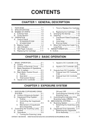
...PARTS 1-4 A. External View 1-4 B. Jam Indicator 1-11 D. When Not Using the Copier for a Long Time 1-16 V. IMAGE FORMATION 1-17 A. Basic Sequence of the A. Inputs to Replace the Cartridge 1-11 2. Controlling the Intensity of Operations (A4, 2 copies 2-3 D. Mechanism of the 1. Outline 3-7 1. PC420/430... Outputs from DC Controller ....2-8 1. Controlling the Copyboard III. Scanning System 3-10 3. Detaching the Copyboard B. CANON PC400/420/430,FC200/220 REV.0 JAN.1998 PRINTED IN JAPAN (IMPRIME AU JAPON) iii SPECIFICATIONS 1-2 III. Cross Section ...
...PARTS 1-4 A. External View 1-4 B. Jam Indicator 1-11 D. When Not Using the Copier for a Long Time 1-16 V. IMAGE FORMATION 1-17 A. Basic Sequence of the A. Inputs to Replace the Cartridge 1-11 2. Controlling the Intensity of Operations (A4, 2 copies 2-3 D. Mechanism of the 1. Outline 3-7 1. PC420/430... Outputs from DC Controller ....2-8 1. Controlling the Copyboard III. Scanning System 3-10 3. Detaching the Copyboard B. CANON PC400/420/430,FC200/220 REV.0 JAN.1998 PRINTED IN JAPAN (IMPRIME AU JAPON) iii SPECIFICATIONS 1-2 III. Cross Section ...
Service Manual
Page 7
... NOTES ABOUT CARTRIDGE .....9-2 A. Image Adjustment Basic 1. Image Leading Edge Non- Image Leading Edge Margin COPYRIGHT © 1998 CANON INC. Detaching the Control Panel Cover 7-4 2. Detaching the Body Cover 7-5 3. Detaching the Bottom Cover 7-8 B. Detaching...THE MACHINE ....8-5 CHAPTER 9 MAINTENANCE AND SERVICING I . PERIODICALLY REPLACED PARTS 9-1 II. Procedure 10-3 Image Width (position of glass).....10-5 II. Detaching the Copyboard Cover 7-9 2. External Covers 7-4 1. CANON PC400/420/430,FC200/220 REV.0 JAN.1998 PRINTED IN JAPAN (IMPRIME AU JAPON)...
... NOTES ABOUT CARTRIDGE .....9-2 A. Image Adjustment Basic 1. Image Leading Edge Non- Image Leading Edge Margin COPYRIGHT © 1998 CANON INC. Detaching the Control Panel Cover 7-4 2. Detaching the Body Cover 7-5 3. Detaching the Bottom Cover 7-8 B. Detaching...THE MACHINE ....8-5 CHAPTER 9 MAINTENANCE AND SERVICING I . PERIODICALLY REPLACED PARTS 9-1 II. Procedure 10-3 Image Width (position of glass).....10-5 II. Detaching the Copyboard Cover 7-9 2. External Covers 7-4 1. CANON PC400/420/430,FC200/220 REV.0 JAN.1998 PRINTED IN JAPAN (IMPRIME AU JAPON)...

Service Manual
Page 9
... Pins by PCB 10-38 1. GENERAL CIRCUIT DIAGRAM...A-5 D. GENERAL TIMING CHART .........A-1 B. CANON PC400/420/430,FC200/220 REV.0 JAN.1998 PRINTED IN JAPAN (IMPRIME AU JAPON) vii B. FUNCTIONS AND ARRANGEMENT OF ELECTRICAL PARTS ........10-34 A. SOLVENTS/OILS TABLE A-8 COPYRIGHT © 1998 CANON INC. DC Controller/DC Power Supply PCB 10-38 2. SIGNALS/ABBREVIATIONS LISTA...
... Pins by PCB 10-38 1. GENERAL CIRCUIT DIAGRAM...A-5 D. GENERAL TIMING CHART .........A-1 B. CANON PC400/420/430,FC200/220 REV.0 JAN.1998 PRINTED IN JAPAN (IMPRIME AU JAPON) vii B. FUNCTIONS AND ARRANGEMENT OF ELECTRICAL PARTS ........10-34 A. SOLVENTS/OILS TABLE A-8 COPYRIGHT © 1998 CANON INC. DC Controller/DC Power Supply PCB 10-38 2. SIGNALS/ABBREVIATIONS LISTA...
Service Manual
Page 11
NAMES OF PARTS 1-4 A. Replacing the Cartridge ........1-11 F. When Not Using the Copier for a Long Time 1-16 V. I. External View 1-4 B. Control Panel 1-6 B. IMAGE FORMATION 1-17 A. FEATURES 1-1 II. Cross Section 1-5 IV. Changing the Density ...........1-14 G. OPERATION 1-6 A. Add Paper Indicator 1-11 E. Cleaning 1-14 H. CANON PC400/420/430,FC200/220 REV.0 JAN.1998 PRINTED IN JAPAN (IMPRIME AU JAPON...
NAMES OF PARTS 1-4 A. Replacing the Cartridge ........1-11 F. When Not Using the Copier for a Long Time 1-16 V. I. External View 1-4 B. Control Panel 1-6 B. IMAGE FORMATION 1-17 A. FEATURES 1-1 II. Cross Section 1-5 IV. Changing the Density ...........1-14 G. OPERATION 1-6 A. Add Paper Indicator 1-11 E. Cleaning 1-14 H. CANON PC400/420/430,FC200/220 REV.0 JAN.1998 PRINTED IN JAPAN (IMPRIME AU JAPON...
Service Manual
Page 16
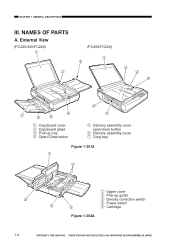
CANON PC400/420/430,FC200/220 REV.0 JAN.1998 PRINTED IN JAPAN (IMPRIME AU JAPON) External View (PC420/430/FC220) Œ (PC400/FC200) Œ Ž Ž ’ ‘ q Copyboard cover w Copyboard glass e Pick-up tray r Open/Close button ‘ &#... u Copy tray Figure 1-301A Œ Ž q Upper cover w Pick-up guide e Density correction switch r Power switch t Cartridge Figure 1-302A 1-4 COPYRIGHT © 1998 CANON INC. CHAPTER 1 GENERAL DESCRIPTION III. NAMES OF...
CANON PC400/420/430,FC200/220 REV.0 JAN.1998 PRINTED IN JAPAN (IMPRIME AU JAPON) External View (PC420/430/FC220) Œ (PC400/FC200) Œ Ž Ž ’ ‘ q Copyboard cover w Copyboard glass e Pick-up tray r Open/Close button ‘ &#... u Copy tray Figure 1-301A Œ Ž q Upper cover w Pick-up guide e Density correction switch r Power switch t Cartridge Figure 1-302A 1-4 COPYRIGHT © 1998 CANON INC. CHAPTER 1 GENERAL DESCRIPTION III. NAMES OF...

Service Manual
Page 26
...if the copy is too dark or too light. Copyboard Glass/Copyboard Cover Wipe the part with a moist cloth; G. then, dry wipe it . 1-14 COPYRIGHT © 1998 CANON INC. then, dry wipe it . Changing the Density PC420/430/FC220 You have a choice of three settings for automatic density adjustment mode (AE); ...Cleaning Advise the user to clean the following if the copies are soiled. 1. If dirt cannot be removed, wipe the part using mild detergent; CHAPTER 1 GENERAL DESCRIPTION F. CANON PC400/420/430,FC200/220 REV.0 JAN.1998 PRINTED IN JAPAN (IMPRIME AU JAPON)
...if the copy is too dark or too light. Copyboard Glass/Copyboard Cover Wipe the part with a moist cloth; G. then, dry wipe it . 1-14 COPYRIGHT © 1998 CANON INC. then, dry wipe it . Changing the Density PC420/430/FC220 You have a choice of three settings for automatic density adjustment mode (AE); ...Cleaning Advise the user to clean the following if the copies are soiled. 1. If dirt cannot be removed, wipe the part using mild detergent; CHAPTER 1 GENERAL DESCRIPTION F. CANON PC400/420/430,FC200/220 REV.0 JAN.1998 PRINTED IN JAPAN (IMPRIME AU JAPON)

Service Manual
Page 31
Inputs to DC Controller ...........2-6 F. Outline 2-1 B. Outputs from DC Controller ....2-8 COPYRIGHT © 1998 CANON INC. Outline of Operations (A4, 2 copies 2-3 D. CANON PC400/420/430,FC200/220 REV.0 JAN.1998 PRINTED IN JAPAN (IMPRIME AU JAPON) 1 I. Main Motor Control Circuit ......2-5 E. Basic Sequence of Electrical Circuit......2-2 C. BASIC OPERATION 2-1 A. CHAPTER 2 BASIC OPERATION This chapter outlines the machine's basic mechanisms and functions, relationship between electrical and mechanical systems, and the timing of operation of respective parts.
Inputs to DC Controller ...........2-6 F. Outline 2-1 B. Outputs from DC Controller ....2-8 COPYRIGHT © 1998 CANON INC. Outline of Operations (A4, 2 copies 2-3 D. CANON PC400/420/430,FC200/220 REV.0 JAN.1998 PRINTED IN JAPAN (IMPRIME AU JAPON) 1 I. Main Motor Control Circuit ......2-5 E. Basic Sequence of Electrical Circuit......2-2 C. BASIC OPERATION 2-1 A. CHAPTER 2 BASIC OPERATION This chapter outlines the machine's basic mechanisms and functions, relationship between electrical and mechanical systems, and the timing of operation of respective parts.

Service Manual
Page 43
.... I. Copyboard Drive System........3-1 II. Outline 3-7 B. Scanning System 3-10 B. Controlling the Scanning Lamp....3-7 A. Operations 3-8 C. EXPOSURE/COPYBOARD DRIVE SYSTEM 3-1 A. Controlling the Intensity of Exposure System ...3-1 B. CANON PC400/420/430,FC200/220 REV.0 JAN.1998 PRINTED IN JAPAN (IMPRIME AU JAPON) 1 CHAPTER 3 EXPOSURE SYSTEM This chapter outlines the machine's copyboard drive and scanning lamp control...
.... I. Copyboard Drive System........3-1 II. Outline 3-7 B. Scanning System 3-10 B. Controlling the Scanning Lamp....3-7 A. Operations 3-8 C. EXPOSURE/COPYBOARD DRIVE SYSTEM 3-1 A. Controlling the Intensity of Exposure System ...3-1 B. CANON PC400/420/430,FC200/220 REV.0 JAN.1998 PRINTED IN JAPAN (IMPRIME AU JAPON) 1 CHAPTER 3 EXPOSURE SYSTEM This chapter outlines the machine's copyboard drive and scanning lamp control...

Service Manual
Page 53
...) and location. 4. The fixing screw for reassembly. 6. CANON PC400/420/430,FC200/220 REV.0 JAN.1998 PRINTED IN JAPAN (IMPRIME AU JAPON) 3-9 CHAPTER 3 EXPOSURE SYSTEM III.MECHANICAL SYSTEM Here, the copier is discussed in terms of its parts removed. Be sure to observe the following for safety before ... wire and varistors is fitted with a washer to keep the washer with the screw when mounting the cover. 5. COPYRIGHT © 1998 CANON INC. One of the mounting screws used on the rear cover is the reverse of its mechanical characteristics and operation and how to protect...
...) and location. 4. The fixing screw for reassembly. 6. CANON PC400/420/430,FC200/220 REV.0 JAN.1998 PRINTED IN JAPAN (IMPRIME AU JAPON) 3-9 CHAPTER 3 EXPOSURE SYSTEM III.MECHANICAL SYSTEM Here, the copier is discussed in terms of its parts removed. Be sure to observe the following for safety before ... wire and varistors is fitted with a washer to keep the washer with the screw when mounting the cover. 5. COPYRIGHT © 1998 CANON INC. One of the mounting screws used on the rear cover is the reverse of its mechanical characteristics and operation and how to protect...
Service Manual
Page 54
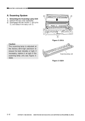
Caution: The scanning lamp is adjusted at the factory with high precision to ensure the best intensity of the scanning lamp unit; CHAPTER 3 EXPOSURE SYSTEM A. Detaching the Scanning Lamp Unit 1) Detach the top cover assembly. 2) Disengage the two hooks q and pins w, and detach the lamp unit e. if necessary, replace it as part of light; CANON PC400/420/430,FC200/220 REV.0 JAN.1998 PRINTED IN JAPAN (IMPRIME AU JAPON) Scanning System disengage 1. see Figure 3302A. Œ Figure 3-301A Scanning lamp unit Figure 3-302A 3-10 COPYRIGHT © 1998 CANON INC.
Caution: The scanning lamp is adjusted at the factory with high precision to ensure the best intensity of the scanning lamp unit; CHAPTER 3 EXPOSURE SYSTEM A. Detaching the Scanning Lamp Unit 1) Detach the top cover assembly. 2) Disengage the two hooks q and pins w, and detach the lamp unit e. if necessary, replace it as part of light; CANON PC400/420/430,FC200/220 REV.0 JAN.1998 PRINTED IN JAPAN (IMPRIME AU JAPON) Scanning System disengage 1. see Figure 3302A. Œ Figure 3-301A Scanning lamp unit Figure 3-302A 3-10 COPYRIGHT © 1998 CANON INC.

Service Manual
Page 57
Sequence of respective parts. Controlling Developing Bias....4-6 E. PC420/430/FC220).......4-14 II. Cartridge 4-17 III. Transfer Charging Roller.......4-20 COPYRIGHT © 1998 CANON INC. Document Density Measurement (AE; CHARGING, DEVELOPING, AND CLEANING SYSTEMS 4-17 A. MECHANICAL SYSTEM............4-18 A. Photosensitive Drum 4-19 B. Transfer Charging Control Circuit 4-10 F. Outline 4-1 B. Primary Charging Control Circuit 4-3 D. I. CANON PC400/420/430,FC200/220...
Sequence of respective parts. Controlling Developing Bias....4-6 E. PC420/430/FC220).......4-14 II. Cartridge 4-17 III. Transfer Charging Roller.......4-20 COPYRIGHT © 1998 CANON INC. Document Density Measurement (AE; CHARGING, DEVELOPING, AND CLEANING SYSTEMS 4-17 A. MECHANICAL SYSTEM............4-18 A. Photosensitive Drum 4-19 B. Transfer Charging Control Circuit 4-10 F. Outline 4-1 B. Primary Charging Control Circuit 4-3 D. I. CANON PC400/420/430,FC200/220...

Service Manual
Page 76
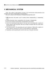
...avoid operating the machine with any of its mechanical characteristics and operation and how to observe the following for disassembly/assembly work . 2. CANON PC400/420/430,FC200/220 REV.0 JAN.1998 PRINTED IN JAPAN (IMPRIME AU JAPON) CHPTER 4 IMAGE FORMATION SYSTEM III.MECHANICAL SYSTEM Here, the ...copier is discussed in terms of its parts removed. 4-18 COPYRIGHT © 1998 CANON INC. Disconnect the power cord for reassembly. 6. Unless otherwise ...
...avoid operating the machine with any of its mechanical characteristics and operation and how to observe the following for disassembly/assembly work . 2. CANON PC400/420/430,FC200/220 REV.0 JAN.1998 PRINTED IN JAPAN (IMPRIME AU JAPON) CHPTER 4 IMAGE FORMATION SYSTEM III.MECHANICAL SYSTEM Here, the ...copier is discussed in terms of its parts removed. 4-18 COPYRIGHT © 1998 CANON INC. Disconnect the power cord for reassembly. 6. Unless otherwise ...

Service Manual
Page 79
I. Outline 5-4 B. Pick-Up Delay Jam (PC420/430/FC220 5-8 D. Pick-Up Stationary Jam ..........5-9 E. Removing the Separation Pad 5-15 COPYRIGHT © 1998 CANON INC. CONTROLLING THE PICK-UP ROLLER 5-2 A. Pick-Up/Feeding Timing Chart (A4, 2 copies 5-5 IV. Paper is ...and functions, relationship between electrical and mechanical systems, and the timing of operation of respective parts. PC420/430/FC220 5-2 B. Delivery Stationary Jam..........5-7 C. MECHANICAL SYSTEM............5-10 A. CANON PC400/420/430,FC200/220 REV.0 JAN.1998 PRINTED IN JAPAN (IMPRIME AU JAPON) 1 PC400/FC200...
I. Outline 5-4 B. Pick-Up Delay Jam (PC420/430/FC220 5-8 D. Pick-Up Stationary Jam ..........5-9 E. Removing the Separation Pad 5-15 COPYRIGHT © 1998 CANON INC. CONTROLLING THE PICK-UP ROLLER 5-2 A. Pick-Up/Feeding Timing Chart (A4, 2 copies 5-5 IV. Paper is ...and functions, relationship between electrical and mechanical systems, and the timing of operation of respective parts. PC420/430/FC220 5-2 B. Delivery Stationary Jam..........5-7 C. MECHANICAL SYSTEM............5-10 A. CANON PC400/420/430,FC200/220 REV.0 JAN.1998 PRINTED IN JAPAN (IMPRIME AU JAPON) 1 PC400/FC200...
Service Manual
Page 90
...to disassemble and assemble it. One of disassembly. 3. MECHANICAL SYSTEM Here, the copier is provided with any of its parts removed. 5-10 COPYRIGHT © 1998 CANON INC. Be sure to keep the washer with a washer to protect against static electricity. be sure to observe the following... for reassembly. 6. If possible, avoid operating the machine with a washer to ensure electric continuity; CANON PC400/420/430,FC200/220 REV.0 JAN.1998 PRINTED IN JAPAN (IMPRIME AU JAPON) CHAPTER 5 PICK-UP/FEEDING SYSTEM V. Be sure to use the...
...to disassemble and assemble it. One of disassembly. 3. MECHANICAL SYSTEM Here, the copier is provided with any of its parts removed. 5-10 COPYRIGHT © 1998 CANON INC. Be sure to keep the washer with a washer to protect against static electricity. be sure to observe the following... for reassembly. 6. If possible, avoid operating the machine with a washer to ensure electric continuity; CANON PC400/420/430,FC200/220 REV.0 JAN.1998 PRINTED IN JAPAN (IMPRIME AU JAPON) CHAPTER 5 PICK-UP/FEEDING SYSTEM V. Be sure to use the...

Service Manual
Page 97
... Temperature 6-3 C. I. OUTLINE OF OPERATIONS .......6-1 A. Controlling the Supply Power to mechanisms and functions, relationship between electrical and mechanical systems, and the timing of operation of respective parts. CANON PC400/420/430,FC200/220 REV.0 JAN.1998 PRINTED IN JAPAN (IMPRIME AU JAPON) 1 MECHANICAL SYSTEM 6-6 A. Protection Mechanisms ..........6-5 II. Fixing Assembly 6-7 COPYRIGHT © 1998...
... Temperature 6-3 C. I. OUTLINE OF OPERATIONS .......6-1 A. Controlling the Supply Power to mechanisms and functions, relationship between electrical and mechanical systems, and the timing of operation of respective parts. CANON PC400/420/430,FC200/220 REV.0 JAN.1998 PRINTED IN JAPAN (IMPRIME AU JAPON) 1 MECHANICAL SYSTEM 6-6 A. Protection Mechanisms ..........6-5 II. Fixing Assembly 6-7 COPYRIGHT © 1998...

Service Manual
Page 104
be sure to protect against static electricity. CANON PC400/420/430,FC200/220 REV.0 JAN.1998 PRINTED IN JAPAN (IMPRIME AU JAPON) Unless otherwise noted, reassembly is the reverse of the mounting screws used on the rear cover is provided with any of its parts removed. 6-6 COPYRIGHT © 1998 CANON INC. One of disassembly. 3. If...
be sure to protect against static electricity. CANON PC400/420/430,FC200/220 REV.0 JAN.1998 PRINTED IN JAPAN (IMPRIME AU JAPON) Unless otherwise noted, reassembly is the reverse of the mounting screws used on the rear cover is provided with any of its parts removed. 6-6 COPYRIGHT © 1998 CANON INC. One of disassembly. 3. If...

Service Manual
Page 111
... mechanisms and functions, relationship between electrical and mechanical systems, and the timing of operation of respective parts. Outline 7-1 B. DC Controller/DC Power Supply PCB 7-11 D. Control Panel PCB 7-14 COPYRIGHT © 1998 CANON INC. CANON PC400/420/430,FC200/220 REV.0 JAN.1998 PRINTED IN JAPAN (IMPRIME AU JAPON) 1 Power Supply PCB 7-2 C. Copyboard Assembly...
... mechanisms and functions, relationship between electrical and mechanical systems, and the timing of operation of respective parts. Outline 7-1 B. DC Controller/DC Power Supply PCB 7-11 D. Control Panel PCB 7-14 COPYRIGHT © 1998 CANON INC. CANON PC400/420/430,FC200/220 REV.0 JAN.1998 PRINTED IN JAPAN (IMPRIME AU JAPON) 1 Power Supply PCB 7-2 C. Copyboard Assembly...

Service Manual
Page 115
... and how to use the washer for the grounding wire and varistors is the reverse of disassembly. 3. be sure to disassemble and assemble it. CANON PC400/420/430,FC200/220 REV.0 JAN.1998 PRINTED IN JAPAN (IMPRIME AU JAPON) 7-3 CHAPTER 7 EXTERNALS/AUXILIARY MECHANISMS II.MECHANICAL SYSTEM Here, the copier is discussed in...
... and how to use the washer for the grounding wire and varistors is the reverse of disassembly. 3. be sure to disassemble and assemble it. CANON PC400/420/430,FC200/220 REV.0 JAN.1998 PRINTED IN JAPAN (IMPRIME AU JAPON) 7-3 CHAPTER 7 EXTERNALS/AUXILIARY MECHANISMS II.MECHANICAL SYSTEM Here, the copier is discussed in...

Service Manual
Page 124
CANON PC400/420/430,FC200/220 REV.0 JAN.1998 PRINTED IN JAPAN (IMPRIME AU JAPON) then, detach the DC controller/DC ...that lead wires are not bitten or shorted, or the connectors are not disconnected. ” Figure 7-204C 7-12 COPYRIGHT © 1998 CANON INC. Caution: The DC controller/DC power supply PCB has high-voltage contacts and pick-up sensor lever; yellow) o, and disengage the ...Disconnect the two connectors u at the rear, and detach the grounding wire i. take extra care not to damage the parts when detaching the PCB. “ ’ Figure 7-203C 9) Remove the screw (M4X8;
CANON PC400/420/430,FC200/220 REV.0 JAN.1998 PRINTED IN JAPAN (IMPRIME AU JAPON) then, detach the DC controller/DC ...that lead wires are not bitten or shorted, or the connectors are not disconnected. ” Figure 7-204C 7-12 COPYRIGHT © 1998 CANON INC. Caution: The DC controller/DC power supply PCB has high-voltage contacts and pick-up sensor lever; yellow) o, and disengage the ...Disconnect the two connectors u at the rear, and detach the grounding wire i. take extra care not to damage the parts when detaching the PCB. “ ’ Figure 7-203C 9) Remove the screw (M4X8;


