
Instruction Manual - English
Page 7
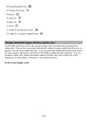
... also create stitch data directly without creating outline data. However, in the same window, although it is possible for PS-300B to display the data separately. You can recognize outline data, manual stitch data, manual feed data, and codes respectively in the design area, by their shapes, colors and so on the sewing machine... first. Resize 49.Copy To 50.Move To 51. 46.Swap Start/End Point 47.Change Data Type 48. You can create both outline and manual stitch data in general, you will be automatically generated from outline data.
... also create stitch data directly without creating outline data. However, in the same window, although it is possible for PS-300B to display the data separately. You can recognize outline data, manual stitch data, manual feed data, and codes respectively in the design area, by their shapes, colors and so on the sewing machine... first. Resize 49.Copy To 50.Move To 51. 46.Swap Start/End Point 47.Change Data Type 48. You can create both outline and manual stitch data in general, you will be automatically generated from outline data.

Instruction Manual - English
Page 8
No. Data type Shape Default color* 1 Outline Solid line Black 2 Connection Stitch/Feed Solid line /Dotted line 3 Manual stitch Solid line Blue Black (The path of a line longer than the maximum stitch length is shown in red.) 4 Manual feed 5 Basting Dotted line with Trim code Dotted line without Trim code Black Black 6 Sewing start point Square Blue 7 Start point of an outline Blue square with "S" Blue 8 End point of an element Red square with "E" Red *: If you prefer, the color of lines can be changed in Property on the Viewdrop-down menu. 8/164
No. Data type Shape Default color* 1 Outline Solid line Black 2 Connection Stitch/Feed Solid line /Dotted line 3 Manual stitch Solid line Blue Black (The path of a line longer than the maximum stitch length is shown in red.) 4 Manual feed 5 Basting Dotted line with Trim code Dotted line without Trim code Black Black 6 Sewing start point Square Blue 7 Start point of an outline Blue square with "S" Blue 8 End point of an element Red square with "E" Red *: If you prefer, the color of lines can be changed in Property on the Viewdrop-down menu. 8/164
Instruction Manual - English
Page 14
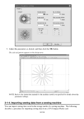
The selected pattern appears in the storage media of a sewing machine. Importing sewing data from a CF (Compact Flash) card. 14/164 The following describes a procedure for details about the parameter settings. 2-1-4. NOTE: Refer to the instruction manual for the machine model you specified for importing sewing data from a sewing machine You can import sewing data saved in the design area. 3. Adjust the parameters as desired, and then click the OK button.
The selected pattern appears in the storage media of a sewing machine. Importing sewing data from a CF (Compact Flash) card. 14/164 The following describes a procedure for details about the parameter settings. 2-1-4. NOTE: Refer to the instruction manual for the machine model you specified for importing sewing data from a sewing machine You can import sewing data saved in the design area. 3. Adjust the parameters as desired, and then click the OK button.
Instruction Manual - English
Page 49
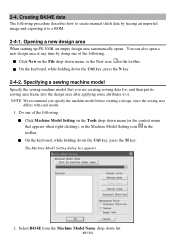
Opening a new design area When starting up PS-300B, an empty design area automatically opens. Do one of the following . On the keyboard, while holding down the Ctrl key, press the M key. 2-4. Specifying a sewing ... from the Machine Model Name drop-down menu, or the New icon in the toolbar. Creating B434E data The following procedure describes how to create manual stitch data by doing one of the following : Click Machine Model Setting on the File drop-down list. 49/164
Opening a new design area When starting up PS-300B, an empty design area automatically opens. Do one of the following . On the keyboard, while holding down the Ctrl key, press the M key. 2-4. Specifying a sewing ... from the Machine Model Name drop-down menu, or the New icon in the toolbar. Creating B434E data The following procedure describes how to create manual stitch data by doing one of the following : Click Machine Model Setting on the File drop-down list. 49/164
Instruction Manual - English
Page 50
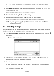
... model for positioning the sewing area frame in order to the design area in the design area. The Open dialog box appears. 2. NOTE: PS-300B can be imported to create manual stitch data. Click the OK button to 3-7-5. Refer to apply the specified settings. 5. Click Import From File on the Image drop-down...
... model for positioning the sewing area frame in order to the design area in the design area. The Open dialog box appears. 2. NOTE: PS-300B can be imported to create manual stitch data. Click the OK button to 3-7-5. Refer to apply the specified settings. 5. Click Import From File on the Image drop-down...

Instruction Manual - English
Page 51
... each corner and at the center of each side of the image, then close the dialog box. With the Trace tool, you can easily create manual stitch data by tracing the imported image. On the keyboard, while holding down menu or click the Resize icon Input the desired size of the...
... each corner and at the center of each side of the image, then close the dialog box. With the Trace tool, you can easily create manual stitch data by tracing the imported image. On the keyboard, while holding down menu or click the Resize icon Input the desired size of the...

Instruction Manual - English
Page 52
... image will need to apply the specified settings. 2. Adjust the setting to match the desired tracing speed. (d) Click the OK button to be traced slowly. Manual stitches are created with the Trace tool by hiding the image using the following steps. (a) Click Show/Hide on the Shape drop-down menu, or...
... image will need to apply the specified settings. 2. Adjust the setting to match the desired tracing speed. (d) Click the OK button to be traced slowly. Manual stitches are created with the Trace tool by hiding the image using the following steps. (a) Click Show/Hide on the Shape drop-down menu, or...

Instruction Manual - English
Page 54
... the last stitch point by clicking the desired two points. 54/164 Click Mirror Copy on the basis of the data You can duplicate the manual stitch data symmetrically on the Modify drop-down the keyboard's Shift key, click the left mouse button at the position where you want to make... any stitch point to the desired position by selecting it with the Select Point tool. 2-4-6. Repeat the above to select the current manual stitch data. 2. While holding down menu, or the Mirror Copy icon in the design area by using the following procedure. Deleting the last stitch point...
... the last stitch point by clicking the desired two points. 54/164 Click Mirror Copy on the basis of the data You can duplicate the manual stitch data symmetrically on the Modify drop-down the keyboard's Shift key, click the left mouse button at the position where you want to make... any stitch point to the desired position by selecting it with the Select Point tool. 2-4-6. Repeat the above to select the current manual stitch data. 2. While holding down menu, or the Mirror Copy icon in the design area by using the following procedure. Deleting the last stitch point...

Instruction Manual - English
Page 80
... the preview size, or click on the File drop-down menu, click Print. The Print dialog box appears. For more details, refer to the user's manual for printing the current data. The same with the Print command on the preview image when the pointer's shape is . Cancel Click this button.
... the preview size, or click on the File drop-down menu, click Print. The Print dialog box appears. For more details, refer to the user's manual for printing the current data. The same with the Print command on the preview image when the pointer's shape is . Cancel Click this button.
Instruction Manual - English
Page 84
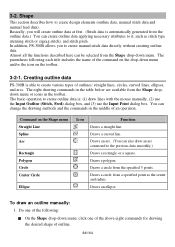
...methods and the commands in the toolbar. 3-2. Basically, you to create various types of an operation. Creating outline data PS-300B is able to create manual stitch data directly without creating outline data. Draws a polygon. Draws an ellipse. Almost all the functions described here can... Arc Rectangle Polygon Circle Center Circle Ellipse Icon Function Draws a straight line. In addition, PS-300B allows you will create outline data at first. (Stitch data is : (1) draw lines with the mouse manually, (2) use the Input Outline (Stitch, Feed) dialog box, and (3) use the Input...
...methods and the commands in the toolbar. 3-2. Basically, you to create various types of an operation. Creating outline data PS-300B is able to create manual stitch data directly without creating outline data. Draws a polygon. Draws an ellipse. Almost all the functions described here can... Arc Rectangle Polygon Circle Center Circle Ellipse Icon Function Draws a straight line. In addition, PS-300B allows you will create outline data at first. (Stitch data is : (1) draw lines with the mouse manually, (2) use the Input Outline (Stitch, Feed) dialog box, and (3) use the Input...

Instruction Manual - English
Page 89
... table for drawing the desired shape of outline. 89/164 To draw an outline using the Input Point dialog box: You can draw an outline manually or by specifying the coordinates of the eight commands in the Length cell. Do one of the following: On the Shape drop-down menu, click...
... table for drawing the desired shape of outline. 89/164 To draw an outline using the Input Point dialog box: You can draw an outline manually or by specifying the coordinates of the eight commands in the Length cell. Do one of the following: On the Shape drop-down menu, click...

Instruction Manual - English
Page 97
... symmetrical shape of the outline is automatically created on the View drop-down menu. 97/164 Creating manual stitch data (Shape-Stitch, ) In PS-300B, stitch data is the general term for each of them). 3. In the design area, draw the desired outline. NOTE:The sewing data created in Property ...
... symmetrical shape of the outline is automatically created on the View drop-down menu. 97/164 Creating manual stitch data (Shape-Stitch, ) In PS-300B, stitch data is the general term for each of them). 3. In the design area, draw the desired outline. NOTE:The sewing data created in Property ...

Instruction Manual - English
Page 98
... shown as a small copyright or trademark symbol or extra securing stitches). When the pointer is the same as outline data: (1) draw lines with the mouse manually, (2) use the Input Outline (Stitch, Feed) dialog box, and (3) use the Input Point dialog box. (Refer to distinguish them easily. Do one...connecting the previous point and the desired position. (The basting data is shown as dotted black lines without Trim codes.) How to create manual stitch, manual feed and basting data The basic operation to create these stitch data is moved into the design area, its shape changes to create ...
... shown as a small copyright or trademark symbol or extra securing stitches). When the pointer is the same as outline data: (1) draw lines with the mouse manually, (2) use the Input Outline (Stitch, Feed) dialog box, and (3) use the Input Point dialog box. (Refer to distinguish them easily. Do one...connecting the previous point and the desired position. (The basting data is shown as dotted black lines without Trim codes.) How to create manual stitch, manual feed and basting data The basic operation to create these stitch data is moved into the design area, its shape changes to create ...

Instruction Manual - English
Page 99
... Continue icon in Property on the keyboard. Input values in allowable length of the data. Repeat steps 1 to 3 to the design area. Drawing manual stitch data by tracing an image (Shape-Trace, ) The Trace command allows you to trace the image. For importing an image, refer to specify...another data linked with the Select Point tool, click the Code icon , then add/delete the Trim code on the point in the toolbar. 3. Manual stitches are connected with the specified trace pitch. 99/164 Complete the Input Outline (Stitch, Feed) dialog box to "3-8. In the design area,...
... Continue icon in Property on the keyboard. Input values in allowable length of the data. Repeat steps 1 to 3 to the design area. Drawing manual stitch data by tracing an image (Shape-Trace, ) The Trace command allows you to trace the image. For importing an image, refer to specify...another data linked with the Select Point tool, click the Code icon , then add/delete the Trim code on the point in the toolbar. 3. Manual stitches are connected with the specified trace pitch. 99/164 Complete the Input Outline (Stitch, Feed) dialog box to "3-8. In the design area,...

Instruction Manual - English
Page 100
... Machine Model Setting on . 1. Right-click once to paste the pattern. The center of the pattern aligns with the mouse. 4. NOTE: Refer to the instruction manual for the parameter settings needed. (A machine model can add any of a specified machine model is pasted on the position where you want to add to...
... Machine Model Setting on . 1. Right-click once to paste the pattern. The center of the pattern aligns with the mouse. 4. NOTE: Refer to the instruction manual for the parameter settings needed. (A machine model can add any of a specified machine model is pasted on the position where you want to add to...

Instruction Manual - English
Page 107
... data: Drag the pointer over the points so that they are complicated. A list box like the following appears to move or delete the selected points manually: Place the pointer on the selected point(s) and drag it . You can use the keyboard's arrow keys to show that the selection frame encloses them...
... data: Drag the pointer over the points so that they are complicated. A list box like the following appears to move or delete the selected points manually: Place the pointer on the selected point(s) and drag it . You can use the keyboard's arrow keys to show that the selection frame encloses them...

Instruction Manual - English
Page 108
...'s Ctrl key while clicking each additional point. On a circle, a punch point can use the keyboard's arrow keys to move or delete the selected punch points manually: Place the pointer on the View drop-down-menu is active, the pointer snaps to display the Input Point dialog box. To select punch points...
...'s Ctrl key while clicking each additional point. On a circle, a punch point can use the keyboard's arrow keys to move or delete the selected punch points manually: Place the pointer on the View drop-down-menu is active, the pointer snaps to display the Input Point dialog box. To select punch points...

Instruction Manual - English
Page 116
... you want to change the sewing order for the item you want to show the specified types of design elements: 1. To hide or show . To manually change and drop it in the Sequence window. (Its number is highlighted.) Then press the keyboard's Delete key. To delete more elements, repeat this operation...
... you want to change the sewing order for the item you want to show the specified types of design elements: 1. To hide or show . To manually change and drop it in the Sequence window. (Its number is highlighted.) Then press the keyboard's Delete key. To delete more elements, repeat this operation...

Instruction Manual - English
Page 126
... the left mouse button. If the sewing area of which you can be available. To delete design elements from the design area: Outline data, manual stitch data, manual feed data, images, stitch points and outline's punch points. 126/164 While holding down the keyboard's Ctrl key, click the left mouse button. On...
... the left mouse button. If the sewing area of which you can be available. To delete design elements from the design area: Outline data, manual stitch data, manual feed data, images, stitch points and outline's punch points. 126/164 While holding down the keyboard's Ctrl key, click the left mouse button. On...

Instruction Manual - English
Page 127
...To duplicate design elements (Edit-Duplicate): This command is released. 127/164 Select one or more design elements. To duplicate design elements manually: You can only be available. Selecting & e diting design elements". 2. NOTE: If no point or design element is clicked....dashes" appears around the element(s). The selected element(s) is duplicated and positioned where the mouse button is available only for outlines, manual stitches and manual feeds. 1. A selection frame of the originals in the toolbar. While holding down menu is selected. NOTE: The deleted elements...
...To duplicate design elements (Edit-Duplicate): This command is released. 127/164 Select one or more design elements. To duplicate design elements manually: You can only be available. Selecting & e diting design elements". 2. NOTE: If no point or design element is clicked....dashes" appears around the element(s). The selected element(s) is duplicated and positioned where the mouse button is available only for outlines, manual stitches and manual feeds. 1. A selection frame of the originals in the toolbar. While holding down menu is selected. NOTE: The deleted elements...


