
Users Manual - English
Page 122
Replacing Maintenance Parts You need to replace the maintenance parts regularly to replace the parts, the following messages will appear on the LCD. REPLACE PF KIT See "Maintenance Messages" in this chapter. 5-2 REPLACE LASER See "Maintenance Messages" in this chapter. REPLACE FUSER See "Maintenance Messages" in this chapter ! ♦ Accessories Toner Cartridge Drum Unit See 'Replacing the Toner Cartridge' in this chapter See 'Replacing the Drum Unit' in this chapter. When it is time to maintain print quality.
Replacing Maintenance Parts You need to replace the maintenance parts regularly to replace the parts, the following messages will appear on the LCD. REPLACE PF KIT See "Maintenance Messages" in this chapter. 5-2 REPLACE LASER See "Maintenance Messages" in this chapter. REPLACE FUSER See "Maintenance Messages" in this chapter ! ♦ Accessories Toner Cartridge Drum Unit See 'Replacing the Toner Cartridge' in this chapter See 'Replacing the Drum Unit' in this chapter. When it is time to maintain print quality.

Users Manual - English
Page 139
LCD Message REPLACE FUSER REPLACE PF KIT1 REPLACE PF KIT2 REPLACE LASER Item Fixing unit Paper feeding kit Paper feeding kit Scanner unit Approximate Life 80,000 pages *1 50,000 pages *1 50,000 pages *1 200,000 pages *1 To ...Purchase Replacement Call Customer Support Call Customer Support Call Customer Support Call Customer Support *1 At 5% print coverage (A4-Letter size). Maintenance Messages CHAPTER 5 MAINTENANCE This printer...
LCD Message REPLACE FUSER REPLACE PF KIT1 REPLACE PF KIT2 REPLACE LASER Item Fixing unit Paper feeding kit Paper feeding kit Scanner unit Approximate Life 80,000 pages *1 50,000 pages *1 50,000 pages *1 200,000 pages *1 To ...Purchase Replacement Call Customer Support Call Customer Support Call Customer Support Call Customer Support *1 At 5% print coverage (A4-Letter size). Maintenance Messages CHAPTER 5 MAINTENANCE This printer...

Users Manual - English
Page 142
Prepare a new Toner Cartridge. See "Maintenance Messages " in Chapter 5. Prepare a new drum unit. See "Maintenance Messages " in Chapter 5. 6-3 See "TONER LOW Message" in Chapter 5. See "CHANGE DRUM SOON Message" in Chapter 5. See "Maintenance Messages " in Chapter 5. Maintenance Messages CHAPTER 6 TROUBLESHOOTING WWaarrnniinngg MMeessssaaggee CHANGE DRUM SOON TONER LOW REPLACE PF KIT1/2 REPLACE FUSER KIT REPLACE LASER KIT AAccttiioonn The drum unit is almost at the end of its life.
Prepare a new Toner Cartridge. See "Maintenance Messages " in Chapter 5. Prepare a new drum unit. See "Maintenance Messages " in Chapter 5. 6-3 See "TONER LOW Message" in Chapter 5. See "CHANGE DRUM SOON Message" in Chapter 5. See "Maintenance Messages " in Chapter 5. Maintenance Messages CHAPTER 6 TROUBLESHOOTING WWaarrnniinngg MMeessssaaggee CHANGE DRUM SOON TONER LOW REPLACE PF KIT1/2 REPLACE FUSER KIT REPLACE LASER KIT AAccttiioonn The drum unit is almost at the end of its life.

Users Manual - English
Page 154
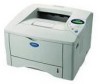
Caution After you touch the internal parts of the printer. ☛ 5. Fig. 6-12 Close the Jam Clear Cover. Fig. 6-13 6-15 CHAPTER 6 TROUBLESHOOTING ! Open the Jam Clear Cover. Close the Face Up Output Tray. Wait for the printer to cool down before you have just used the printer, some internal parts of the fuser unit. Pull the jammed paper out of the printer are extremely hot! Jam Clear Cover ☛ 6.
Caution After you touch the internal parts of the printer. ☛ 5. Fig. 6-12 Close the Jam Clear Cover. Fig. 6-13 6-15 CHAPTER 6 TROUBLESHOOTING ! Open the Jam Clear Cover. Close the Face Up Output Tray. Wait for the printer to cool down before you have just used the printer, some internal parts of the fuser unit. Pull the jammed paper out of the printer are extremely hot! Jam Clear Cover ☛ 6.

Users Manual - English
Page 156
Fig. 6-15 6-17 Pull the jammed paper out of the fuser unit. Open the Face Up Output Tray. Fig. 6-14 ☛ 2. JAM DUPLEX CHAPTER 6 TROUBLESHOOTING JAM DUPLEX Follow the instructions below to clear a paper jam: ☛ 1.
Fig. 6-15 6-17 Pull the jammed paper out of the fuser unit. Open the Face Up Output Tray. Fig. 6-14 ☛ 2. JAM DUPLEX CHAPTER 6 TROUBLESHOOTING JAM DUPLEX Follow the instructions below to clear a paper jam: ☛ 1.
Users Manual - English
Page 161
Jam Clear Cover Fig. 6-23 ☛ 7. Close the Jam Clear Cover. Close the Front Cover. ☛ 10. Close the Face Up Output Tray. ☛ 8. Open the Jam Clear Cover. Pull the jammed paper out of the fuser unit. Put the Paper Cassette back in the printer. 6-22 Put the drum unit back into the printer. ☛ 9. ☛ 6.
Jam Clear Cover Fig. 6-23 ☛ 7. Close the Jam Clear Cover. Close the Front Cover. ☛ 10. Close the Face Up Output Tray. ☛ 8. Open the Jam Clear Cover. Pull the jammed paper out of the fuser unit. Put the Paper Cassette back in the printer. 6-22 Put the drum unit back into the printer. ☛ 9. ☛ 6.
Users Manual - English
Page 203
... interface mode 3-27 IP address 3-29 J Job Cancel button 3-4 L labels 1-27 LCD 3-14, 6-1 LCD display 3-14 LED 3-13 lower tray unit 4-2 LT-500 4-2 M Macintosh 2-19 maintenance message 6-3 manual feed 1-36 memory 4-10 Menu button 3-11 Multi-purpose tray 1-17 N Network board ... wire 5-17 print media 1-7, 1-9, A-5 print menu 3-33 print menu mode 3-22 print quality 2-4 printable area 1-13 printer driver 2-1 printer status message 3-15 Q quality mode 3-32 R RAM 4-9 replace fuser 5-19 replace laser 5-19 replace pf kit1 5-19 replace pf kit2 5-19 reprint 2-7, 3-5 I -2
... interface mode 3-27 IP address 3-29 J Job Cancel button 3-4 L labels 1-27 LCD 3-14, 6-1 LCD display 3-14 LED 3-13 lower tray unit 4-2 LT-500 4-2 M Macintosh 2-19 maintenance message 6-3 manual feed 1-36 memory 4-10 Menu button 3-11 Multi-purpose tray 1-17 N Network board ... wire 5-17 print media 1-7, 1-9, A-5 print menu 3-33 print menu mode 3-22 print quality 2-4 printable area 1-13 printer driver 2-1 printer status message 3-15 Q quality mode 3-32 R RAM 4-9 replace fuser 5-19 replace laser 5-19 replace pf kit1 5-19 replace pf kit2 5-19 reprint 2-7, 3-5 I -2

Parts List
Page 4
PR2002076 2. FRAME / DRIVE UNIT REF.NO. LASER UNIT REF.NO. CODE Q'TY DESCRIPTION 1 LJ7004001 1 LASER UNIT (SP) 2 087321615 3 TAPTITE, CUP S M3X16 SYMBOL PR2002076 REMARK ADD SYMBOL REMARK MODEL HL-1850/1870N 84U-Z23/Z24-020 - 2 - CODE Q'TY DESCRIPTION 1 LJ5980001 1 MAIN MOTOR ASSY HE 2 ... 21 000300415 1 SCREW, BIND M3X4 22 085310815 1 TAPTITE, BIND B M3X8 23 LJ5966001 1 FUSER DRIVE GEAR 1HE 24 LJ5967001 1 FUSER DRIVE GEAR 2HE 25 LJ5930001 1 FEED ROLLER GEAR SHAFT 26 LJ5114001 1 SPRING, EXTENSION P/R MODEL HL-1850/1870N 84U-Z23/Z24-010 T/I NO. 1.
PR2002076 2. FRAME / DRIVE UNIT REF.NO. LASER UNIT REF.NO. CODE Q'TY DESCRIPTION 1 LJ7004001 1 LASER UNIT (SP) 2 087321615 3 TAPTITE, CUP S M3X16 SYMBOL PR2002076 REMARK ADD SYMBOL REMARK MODEL HL-1850/1870N 84U-Z23/Z24-020 - 2 - CODE Q'TY DESCRIPTION 1 LJ5980001 1 MAIN MOTOR ASSY HE 2 ... 21 000300415 1 SCREW, BIND M3X4 22 085310815 1 TAPTITE, BIND B M3X8 23 LJ5966001 1 FUSER DRIVE GEAR 1HE 24 LJ5967001 1 FUSER DRIVE GEAR 2HE 25 LJ5930001 1 FEED ROLLER GEAR SHAFT 26 LJ5114001 1 SPRING, EXTENSION P/R MODEL HL-1850/1870N 84U-Z23/Z24-010 T/I NO. 1.

Service Manual
Page 149
CHAPTER 4 DISASSEMBLY AND RE-ASSEMBLY (11) Remove the four cup S tite 3x6 screws and disconnect the harness to remove the main motor ASSY from the drive sub ASSY A. Solenoid unit Ga 5 Main frame c1l C, Taptite, bind B M4x10 Fig. 4-78 Screw, cup S tite 3x6 Screw, cup S tite 3x6 ''‹ r ) Drive sub ASSY A Cg 7 (A) , Fuser drive gear Main motor ASSY Fig. 4-77 (8) Place the main frame so that the drive unit side is at the right as the figure shown below. (9) Remove the two bind B M4x10 Taptite screws.
CHAPTER 4 DISASSEMBLY AND RE-ASSEMBLY (11) Remove the four cup S tite 3x6 screws and disconnect the harness to remove the main motor ASSY from the drive sub ASSY A. Solenoid unit Ga 5 Main frame c1l C, Taptite, bind B M4x10 Fig. 4-78 Screw, cup S tite 3x6 Screw, cup S tite 3x6 ''‹ r ) Drive sub ASSY A Cg 7 (A) , Fuser drive gear Main motor ASSY Fig. 4-77 (8) Place the main frame so that the drive unit side is at the right as the figure shown below. (9) Remove the two bind B M4x10 Taptite screws.

Service Manual
Page 175
...PF KIT1 REPLACE PF KIT2 REPLACE FUSER Indicates that you selected in the current driver setting. Refer to the printer. Set the correct paper that you want to use into the Tray 1. Prepare a new drum unit. HL-1850/1870N SERVICE MANUAL Error Message PRINT...DIMM. (4) Set page protect to subsection 3.11 Laser Unit' in CHAPTER 4. Replace the fixing unit. Purchase a new toner cartridge in the printer. (2) Reduce the complexity of life. Send correct data to subsection 3.12 `Fixing Unit" REPLACE LASER Replace the laser unit. Replace the paper feeding kit (pad holder ...
...PF KIT1 REPLACE PF KIT2 REPLACE FUSER Indicates that you selected in the current driver setting. Refer to the printer. Set the correct paper that you want to use into the Tray 1. Prepare a new drum unit. HL-1850/1870N SERVICE MANUAL Error Message PRINT...DIMM. (4) Set page protect to subsection 3.11 Laser Unit' in CHAPTER 4. Replace the fixing unit. Purchase a new toner cartridge in the printer. (2) Reduce the complexity of life. Send correct data to subsection 3.12 `Fixing Unit" REPLACE LASER Replace the laser unit. Replace the paper feeding kit (pad holder ...

Service Manual
Page 178
... chapter. NV-RAM reading error Turn off the printer. Wait a few seconds, and then turn it on again. Flash writing error Turn off the printer. Wait a few seconds, and then turn it on again. HL-1850/1870N SERVICE MANUAL PR2001022 Error Messages ERROR E49 ERROR... Turn off the printer. NV-RAM writing error Turn off the printer. Refer to M-4 `No paper supplied' in this chapter. Refer to M-8 `Scanner failure' in this chapter. Malfunction of fuser detected Malfunction of laser beam detector Malfunction of laser unit motor Malfunction of fuser detected by hard wear...
... chapter. NV-RAM reading error Turn off the printer. Wait a few seconds, and then turn it on again. Flash writing error Turn off the printer. Wait a few seconds, and then turn it on again. HL-1850/1870N SERVICE MANUAL PR2001022 Error Messages ERROR E49 ERROR... Turn off the printer. NV-RAM writing error Turn off the printer. Refer to M-4 `No paper supplied' in this chapter. Refer to M-8 `Scanner failure' in this chapter. Malfunction of fuser detected Malfunction of laser beam detector Malfunction of laser unit motor Malfunction of fuser detected by hard wear...

Service Manual
Page 185
Pull the jammed paper out of the fuser unit. Fig. 6-16 Ne. Jam clear cover O Fig. 6-14 (6) Close the jam clear cover. Close the face up output tray (rear cover). Fig. 6-17 Fig. 6-15 JAM DUPLEX (1) Open the face up output tray (rear cover). (7) Install the drum unit assembly into the printer. (8) Close the front cover. HL-1850/1870N SERVICE MANUAL (5) Open the jam clear cover.
Pull the jammed paper out of the fuser unit. Fig. 6-16 Ne. Jam clear cover O Fig. 6-14 (6) Close the jam clear cover. Close the face up output tray (rear cover). Fig. 6-17 Fig. 6-15 JAM DUPLEX (1) Open the face up output tray (rear cover). (7) Install the drum unit assembly into the printer. (8) Close the front cover. HL-1850/1870N SERVICE MANUAL (5) Open the jam clear cover.

Service Manual
Page 186
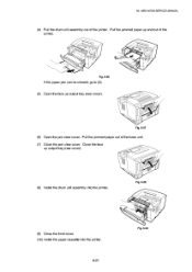
Fig. 6-19 / (5) Pull the jammed paper out of the printer. r) 4 Fig. 6-18 7 4 (4) Pull the duplex tray and paper cassette out of the printer. (6) Install the duplex tray and paper cassette into the printer. 6-18 Fig. 6-20 / Cc(2.-• Fig. 6-21 / / Fig. 6-22 CHAPTER 6 TROUBLESHOOTING (2) Pull the jammed paper out of the fuser unit. (3) Close the face up output tray (rear cover). If the paper jam can not be cleared, go to the next step.
Fig. 6-19 / (5) Pull the jammed paper out of the printer. r) 4 Fig. 6-18 7 4 (4) Pull the duplex tray and paper cassette out of the printer. (6) Install the duplex tray and paper cassette into the printer. 6-18 Fig. 6-20 / Cc(2.-• Fig. 6-21 / / Fig. 6-22 CHAPTER 6 TROUBLESHOOTING (2) Pull the jammed paper out of the fuser unit. (3) Close the face up output tray (rear cover). If the paper jam can not be cleared, go to the next step.
Service Manual
Page 189
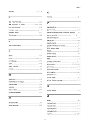
Pull the jammed paper out of the printer. HL-1850/1870N SERVICE MANUAL (4) Pull the drum unit assembly out of the fuser unit. (7) Close the jam clear cover. Close the face up output tray (rear cover). Fig. 6-28 (9) Close the front cover. (10) Install the paper cassette into the printer. Pull the jammed paper up and out of the printer. • ( me Fig. 6-26 If the paper jam can be cleared, go to (8). (5) Open the face up output tray (rear cover). (8) Install the drum unit assembly into the printer. 6-21 Fig. 6-29 Fig. 6-27 (6) Open the jam clear cover.
Pull the jammed paper out of the printer. HL-1850/1870N SERVICE MANUAL (4) Pull the drum unit assembly out of the fuser unit. (7) Close the jam clear cover. Close the face up output tray (rear cover). Fig. 6-28 (9) Close the front cover. (10) Install the paper cassette into the printer. Pull the jammed paper up and out of the printer. • ( me Fig. 6-26 If the paper jam can be cleared, go to (8). (5) Open the face up output tray (rear cover). (8) Install the drum unit assembly into the printer. 6-21 Fig. 6-29 Fig. 6-27 (6) Open the jam clear cover.

Service Manual
Page 199
...Result Remedy No Reconnect the connector. No Reinstall the thermistor properly. Yes Replace the laser unit. Is it open circuit? Is the thermistor installed properly? 4 Remove the fixing unit and measure the resistance of the scanner motor connector P12 on the engine PCB good?...however, that this problem may be clearedifleaving the printerpower ON for ten minutes. • If the heater is hot. 6-32 M-9 Fuser failure Possible cause Poor thermistor harness contact Blown thermal fuse Thermistor failure Halogen heater lamp failure Heater harness connection failure Step 1 2 3...
...Result Remedy No Reconnect the connector. No Reinstall the thermistor properly. Yes Replace the laser unit. Is it open circuit? Is the thermistor installed properly? 4 Remove the fixing unit and measure the resistance of the scanner motor connector P12 on the engine PCB good?...however, that this problem may be clearedifleaving the printerpower ON for ten minutes. • If the heater is hot. 6-32 M-9 Fuser failure Possible cause Poor thermistor harness contact Blown thermal fuse Thermistor failure Halogen heater lamp failure Heater harness connection failure Step 1 2 3...

Service Manual
Page 245
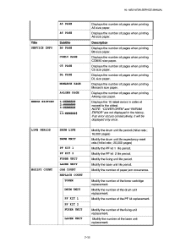
...display. 3.2 Function Table The following information will get various printer information. Title SERVICE INFO Subtitle PAGE COUNT JAM COUNT TONER CHANGE DRUM CHANGE PF KIT 1 CHANGE PF KIT 2 CHANGE FUSER CHANGE LASER CHANGE COVERAGE A4 PAGE LETTER PAGE LEGAL PAGE EXECUTIVE PAGE...PR2001036 3. Displays the number of pages when printing JIS B5 size paper 7-10 Displays the number of the fuser unit replacement. Displays the number of the laser unit replacement. COVERAGE counter can be available with this operation. Displays the number of the toner cartridge replacement . ...
...display. 3.2 Function Table The following information will get various printer information. Title SERVICE INFO Subtitle PAGE COUNT JAM COUNT TONER CHANGE DRUM CHANGE PF KIT 1 CHANGE PF KIT 2 CHANGE FUSER CHANGE LASER CHANGE COVERAGE A4 PAGE LETTER PAGE LEGAL PAGE EXECUTIVE PAGE...PR2001036 3. Displays the number of pages when printing JIS B5 size paper 7-10 Displays the number of the fuser unit replacement. Displays the number of the laser unit replacement. COVERAGE counter can be available with this operation. Displays the number of the toner cartridge replacement . ...
Service Manual
Page 246
HL-1850/1870N SERVICE MANUAL A5 PAGE A6 PAGE Title SERVICE INFO Subtitle B6 PAGE COM10 PAGE C5 PAGE DL PAGE MONARCH PAGE A4 LONG PAGE ERROR HI STORY 1:####### 2:####### 3 : ####### 10 :####### LIFE PERIOD DRUM LIFE DRUM UNIT MODIFY COUNT PF KIT 1 PF KIT 2 FUSER UNIT LASER UNIT JAM COUNT REPLACE COUNT TONER DRUM UNIT PF KIT 1 PF KIT 2 FUSER UNIT LASER UNIT Displays the...
HL-1850/1870N SERVICE MANUAL A5 PAGE A6 PAGE Title SERVICE INFO Subtitle B6 PAGE COM10 PAGE C5 PAGE DL PAGE MONARCH PAGE A4 LONG PAGE ERROR HI STORY 1:####### 2:####### 3 : ####### 10 :####### LIFE PERIOD DRUM LIFE DRUM UNIT MODIFY COUNT PF KIT 1 PF KIT 2 FUSER UNIT LASER UNIT JAM COUNT REPLACE COUNT TONER DRUM UNIT PF KIT 1 PF KIT 2 FUSER UNIT LASER UNIT Displays the...

Service Manual
Page 247
FUSER UNIT Modify the fixing unit remaining life counters. CLEAR ERROR HIST Clear error histories. ,,, 7-12 CHAPTER 7 HIDDEN FUNCTIONS Title MODIFY COUNT RESET COUNT Subtitle REMAIN LIFE DRUM UNIT PF KIT 1 PF KIT 2 Description Modify the drum unit remaining life counters. Modify the PF kit remaining life counters. CLEAR COVERAGE Initialize average coverage counter. LASER UNIT Modify the laser unit remaining life counters.
FUSER UNIT Modify the fixing unit remaining life counters. CLEAR ERROR HIST Clear error histories. ,,, 7-12 CHAPTER 7 HIDDEN FUNCTIONS Title MODIFY COUNT RESET COUNT Subtitle REMAIN LIFE DRUM UNIT PF KIT 1 PF KIT 2 Description Modify the drum unit remaining life counters. Modify the PF kit remaining life counters. CLEAR COVERAGE Initialize average coverage counter. LASER UNIT Modify the laser unit remaining life counters.


