
Instruction Manual - English
Page 6
Standard sewing pattern list 3 3. Ruler 5 3-5. Installing the flange nut 9... 5-10. Using the program memos 53 5-13. Winding the lower thread 59 7-4. Thread tension 61 HE-800A Auxiliary table 6 3-7. Installing the belt cover 26 5. OPERATION 27 5-1. Checking the length of each operation ... 2-2. Table processing diagram 7 4-2. Installing the transformer 17 4-12. Lubricating the rotary hook 25 4-18. OPTIONAL PARTS 4 3-1. INSTALLATION 7 4-1. Changing the treadle unit installation position (horizontal positioning only 22 4-15. Operating the standing ...
Standard sewing pattern list 3 3. Ruler 5 3-5. Installing the flange nut 9... 5-10. Using the program memos 53 5-13. Winding the lower thread 59 7-4. Thread tension 61 HE-800A Auxiliary table 6 3-7. Installing the belt cover 26 5. OPERATION 27 5-1. Checking the length of each operation ... 2-2. Table processing diagram 7 4-2. Installing the transformer 17 4-12. Lubricating the rotary hook 25 4-18. OPTIONAL PARTS 4 3-1. INSTALLATION 7 4-1. Changing the treadle unit installation position (horizontal positioning only 22 4-15. Operating the standing ...
Instruction Manual - English
Page 7
...-2. Initializing a single program 80 13. CHANGING FUNCTIONS USING THE DIP SWITCHES 81 13-1. Panel DIP switches 81 13-2. Circuit board DIP switches 83 14. GAUGE PARTS LIST 89 16. Skipped stitches 93 16-3. Uneven seams (1) ...... At the sewing start ....96 16-7. Uneven seams (2) ...... Seam lifts up at the sewing start 95 16... 16-14. Unraveling of thread trimmed by upper thread trimmer assembly 101 16-15. Upper thread mis-trimming 102 16-16. Needle breakage 103 HE-800A
...-2. Initializing a single program 80 13. CHANGING FUNCTIONS USING THE DIP SWITCHES 81 13-1. Panel DIP switches 81 13-2. Circuit board DIP switches 83 14. GAUGE PARTS LIST 89 16. Skipped stitches 93 16-3. Uneven seams (1) ...... At the sewing start ....96 16-7. Uneven seams (2) ...... Seam lifts up at the sewing start 95 16... 16-14. Unraveling of thread trimmed by upper thread trimmer assembly 101 16-15. Upper thread mis-trimming 102 16-16. Needle breakage 103 HE-800A
Instruction Manual - English
Page 97
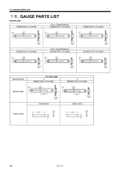
GAUGE PARTS LIST Needle plate S50663-001 (1.2 mmS) S50664-001 (1.4 mmS) S50665-001 (1.6 mmS) S51248-101 (1.2 mmS) S51249-101 (1.4 mmS) S51250-101 (1.6 mmS) Specifications Needle plate For flat cutter -2 S50321-001 (1.2 mmS) -3 S50322-101 (1.2 mmS) Plastic plate 151843-001 156612-001 89 HE-800A GAUGE PARTS LIST 15. 15.
GAUGE PARTS LIST Needle plate S50663-001 (1.2 mmS) S50664-001 (1.4 mmS) S50665-001 (1.6 mmS) S51248-101 (1.2 mmS) S51249-101 (1.4 mmS) S51250-101 (1.6 mmS) Specifications Needle plate For flat cutter -2 S50321-001 (1.2 mmS) -3 S50322-101 (1.2 mmS) Plastic plate 151843-001 156612-001 89 HE-800A GAUGE PARTS LIST 15. 15.

Instruction Manual - English
Page 98
15. GAUGE PARTS LIST [A] Work clamp assembly, with finger guard [B] Work clamp assembly [C] Finger guard [D] Work clamp A S37101-102 (16 mmRS) A S37100-102 (25 mmRS) A S55347-002 (25 mmRSW) A ... D 145136-001 D 144630-001 D S55348-001 D 144632-001 Sewing area 4 × 20 Sewing area 4 × 32 Sewing area 5.4 × 32 Sewing area 5.4 × 40 HE-800A 90
15. GAUGE PARTS LIST [A] Work clamp assembly, with finger guard [B] Work clamp assembly [C] Finger guard [D] Work clamp A S37101-102 (16 mmRS) A S37100-102 (25 mmRS) A S55347-002 (25 mmRSW) A ... D 145136-001 D 144630-001 D S55348-001 D 144632-001 Sewing area 4 × 20 Sewing area 4 × 32 Sewing area 5.4 × 32 Sewing area 5.4 × 40 HE-800A 90
Parts Manual - English
Page 3
... 7 E. Thread breakage detector mechanism 19 K. Control box (PCB) mechanism 47 U. Safety cover 55 Y. Accessories 61 Z3. Gauge parts list 67 Wa. Needle bar and thread take-up mechanism ...... 3 C. Lower shaft mechanism 23 M. Threading mechanism 29 P. Control box mechanism... F. Cutter mechanism 17 J. Bobbin winder mechanism 33 Q. Upper thread trimmer mechanism 35 R. Gauge parts list 66 Ga3. Accessories 59 Z2. Control box mechanism 45 T3. Gauge parts list 65 Ga2. Lower thread trimmer mechanism 37 S. Motor mechanism 53 X. This book was prepared based...
... 7 E. Thread breakage detector mechanism 19 K. Control box (PCB) mechanism 47 U. Safety cover 55 Y. Accessories 61 Z3. Gauge parts list 67 Wa. Needle bar and thread take-up mechanism ...... 3 C. Lower shaft mechanism 23 M. Threading mechanism 29 P. Control box mechanism... F. Cutter mechanism 17 J. Bobbin winder mechanism 33 Q. Upper thread trimmer mechanism 35 R. Gauge parts list 66 Ga3. Accessories 59 Z2. Control box mechanism 45 T3. Gauge parts list 65 Ga2. Lower thread trimmer mechanism 37 S. Motor mechanism 53 X. This book was prepared based...


