Owner's guide
Page 3
...guide 5 Glossary of terms 5 For your records 7 System Setup 8 Unpacking 8 Selecting locations for your Model 3•2•1 speakers and media center 9 Placing the small speakers 9 Media center placement 10 Placement choices for the Acoustimass® module 11 When the system setup is completed 12 Making the...16 Connecting your VCR to the system 16 Attaching the supplied antennas 17 Connecting cable FM radio 18 Make the power connection after all the others 18 Turning off the internal speakers in your TV 18 Installing remote control batteries 19 Other choices 19 Connecting ...
...guide 5 Glossary of terms 5 For your records 7 System Setup 8 Unpacking 8 Selecting locations for your Model 3•2•1 speakers and media center 9 Placing the small speakers 9 Media center placement 10 Placement choices for the Acoustimass® module 11 When the system setup is completed 12 Making the...16 Connecting your VCR to the system 16 Attaching the supplied antennas 17 Connecting cable FM radio 18 Make the power connection after all the others 18 Turning off the internal speakers in your TV 18 Installing remote control batteries 19 Other choices 19 Connecting ...
Owner's guide
Page 8
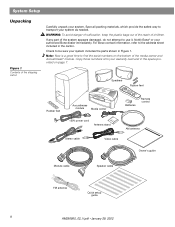
... sheet included in Figure 1. Copy those numbers onto your authorized Bose dealer immediately. For Bose contact information, refer to transport your system. System Setup Unpacking Figure... 1 Contents of the shipping carton Carefully unpack your system as needed. If any part of children. Speakers Rubber feet Rubber feet Acoustimass module Media center Batteries Remote control 120V power cord Antenna stand AM antenna Stereo cable Video cable Owner's guide Module cable Speaker cable...
... sheet included in Figure 1. Copy those numbers onto your authorized Bose dealer immediately. For Bose contact information, refer to transport your system. System Setup Unpacking Figure... 1 Contents of the shipping carton Carefully unpack your system as needed. If any part of children. Speakers Rubber feet Rubber feet Acoustimass module Media center Batteries Remote control 120V power cord Antenna stand AM antenna Stereo cable Video cable Owner's guide Module cable Speaker cable...
Owner's guide
Page 10
... top of the TV or to the left and right of the cables connected to the Acoustimass® module and the speakers. In that position (with the Bose logo right side up to 3 feet (1 meter) from the edges of the TV screen to Figure 3 on page 9) and at roughly ...when they can also be mounted on page 40. Bose® recommends a maximum distance of 3 feet from the picture. If additional audio cables are on their bottom surface (Figure 4). Place the speakers up ), they are needed for all the cables to Accessories on optional Bose brackets, table stands, or floor stands. ...
... top of the TV or to the left and right of the cables connected to the Acoustimass® module and the speakers. In that position (with the Bose logo right side up to 3 feet (1 meter) from the edges of the TV screen to Figure 3 on page 9) and at roughly ...when they can also be mounted on page 40. Bose® recommends a maximum distance of 3 feet from the picture. If additional audio cables are on their bottom surface (Figure 4). Place the speakers up ), they are needed for all the cables to Accessories on optional Bose brackets, table stands, or floor stands. ...
Owner's guide
Page 11
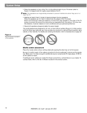
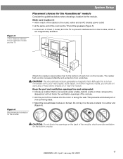
... immediate risk to the music center and an AC (mains) power outlet • at the same end of the room as the TV and the speakers (Figure 5) • a minimum of the module into the room or along the wall. MUSIC CENTER AC INPUT CAUTION: Do not block the openings on the... 11 This prevents a blocked port or over-powering bass. • Stand the Acoustimass module on its side or stand it : • within reach of the cables to your video tapes, audio tapes, and other magnetic media, you should not store any of the module, which is not magnetically shielded Figure 6 Recommended...
... immediate risk to the music center and an AC (mains) power outlet • at the same end of the room as the TV and the speakers (Figure 5) • a minimum of the module into the room or along the wall. MUSIC CENTER AC INPUT CAUTION: Do not block the openings on the... 11 This prevents a blocked port or over-powering bass. • Stand the Acoustimass module on its side or stand it : • within reach of the cables to your video tapes, audio tapes, and other magnetic media, you should not store any of the module, which is not magnetically shielded Figure 6 Recommended...
Owner's guide
Page 13
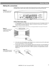
... L VIDEO INPUT C VIDEO OUTPUT C AUDIO OUTPUT L R S S R SPEAKERS ACOUSTIMASS MODULE Figure 9 Completed connection of speaker cable to the right of the speaker cable into the rear jack on the left speaker (to the left of the TV as necessary to reach each speaker. 3. Plug the LEFT connector of the separated cable into the SPEAKERS connector (Figure 8). Figure 8 Connection panel on...
... L VIDEO INPUT C VIDEO OUTPUT C AUDIO OUTPUT L R S S R SPEAKERS ACOUSTIMASS MODULE Figure 9 Completed connection of speaker cable to the right of the speaker cable into the rear jack on the left speaker (to the left of the TV as necessary to reach each speaker. 3. Plug the LEFT connector of the separated cable into the SPEAKERS connector (Figure 8). Figure 8 Connection panel on...
Owner's guide
Page 14
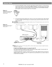
... LEFT To TV video input VIDEO OUTPUT Speaker cable VIDEO D L 75 Ω FM AM LOOP ANTENNA ANTENNA OPTICAL R AUDIO INPUT IDEO 2 L D R D AUX L VIDEO INPUT C VIDEO OUTPUT C AUDIO OUTPUT L SPEAKERS R S ACOUSTIMASS MODULE S R AC input jack AC INPUT MUSIC CENTER Acoustimass module cable Note: Before using your Bose® dealer or a local electronics retailer. 14 AM256950_02_V.pdf...
... LEFT To TV video input VIDEO OUTPUT Speaker cable VIDEO D L 75 Ω FM AM LOOP ANTENNA ANTENNA OPTICAL R AUDIO INPUT IDEO 2 L D R D AUX L VIDEO INPUT C VIDEO OUTPUT C AUDIO OUTPUT L SPEAKERS R S ACOUSTIMASS MODULE S R AC input jack AC INPUT MUSIC CENTER Acoustimass module cable Note: Before using your Bose® dealer or a local electronics retailer. 14 AM256950_02_V.pdf...
Owner's guide
Page 16
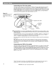
...INPUT VIDEO 2 L D R D AUX L VIDEO INPUT C VIDEO OUTPUT C AUDIO OUTPUT L SPEAKERS R S ACOUSTIMASS MODULE S R Media center VIDEO IN AUDIO OUT L R TV Supplied video cable TV/VIDEO, INPUT, or AUX IN RCA cable TV/VIDEO TV remote Important Note: Your television must be set properly, you connected your TV...button labeled either "TV/VIDEO," "INPUT," or "AUX IN" (or a similar term) for this connection, which include a standard TV cable connector, have an S-VIDEO output, you connected your TV to the COMPOSITE VIDEO INPUT on your local electronics store. If you may hear the...
...INPUT VIDEO 2 L D R D AUX L VIDEO INPUT C VIDEO OUTPUT C AUDIO OUTPUT L SPEAKERS R S ACOUSTIMASS MODULE S R Media center VIDEO IN AUDIO OUT L R TV Supplied video cable TV/VIDEO, INPUT, or AUX IN RCA cable TV/VIDEO TV remote Important Note: Your television must be set properly, you connected your TV...button labeled either "TV/VIDEO," "INPUT," or "AUX IN" (or a similar term) for this connection, which include a standard TV cable connector, have an S-VIDEO output, you connected your TV to the COMPOSITE VIDEO INPUT on your local electronics store. If you may hear the...

Owner's guide
Page 17
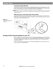
...8486; FM AM LOOP ANTENNA ANTENNA OPTICAL R AUDIO INPUT IDEO 2 L D R D AUX L VIDEO INPUT C VIDEO AUDIO OUTPUT OUTPUT C L SPEAKERS R S S R ACOUSTIMASS MODULE FM antenna Plug the connector into the AM antenna jack on the media center Figure 16 Adding the AM and FM ... R AUDIO INPUT VIDEO 2 L D R D AUX L VIDEO INPUT C VIDEO AUDIO OUTPUT OUTPUT C L SPEAKERS R S ACOUSTIMASS MODULE S R Media center VIDEO OUT AUDIO OUT Video cable L R VCR RCA cable Note: Do not connect the video output of each antenna to ensure the best reception. Extend the antenna as ...
...8486; FM AM LOOP ANTENNA ANTENNA OPTICAL R AUDIO INPUT IDEO 2 L D R D AUX L VIDEO INPUT C VIDEO AUDIO OUTPUT OUTPUT C L SPEAKERS R S S R ACOUSTIMASS MODULE FM antenna Plug the connector into the AM antenna jack on the media center Figure 16 Adding the AM and FM ... R AUDIO INPUT VIDEO 2 L D R D AUX L VIDEO INPUT C VIDEO AUDIO OUTPUT OUTPUT C L SPEAKERS R S ACOUSTIMASS MODULE S R Media center VIDEO OUT AUDIO OUT Video cable L R VCR RCA cable Note: Do not connect the video output of each antenna to ensure the best reception. Extend the antenna as ...
Owner's guide
Page 18
This connection is received by the media center. If necessary, contact a qualified installer. AC outlet Turning off the internal speakers, you listen to TV sound through the cable service to your TV owner's guide for different TVs). To connect to this service, contact your TV to its lowest setting. 18 ... may be different for detailed instructions. If your TV does not have an option to turn off the internal speakers in your TV When you can reduce the volume of your cable TV provider for assistance. Insert the large end of the cord into the AC INPUT jack on the module...
This connection is received by the media center. If necessary, contact a qualified installer. AC outlet Turning off the internal speakers, you listen to TV sound through the cable service to your TV owner's guide for different TVs). To connect to this service, contact your TV to its lowest setting. 18 ... may be different for detailed instructions. If your TV does not have an option to turn off the internal speakers in your TV When you can reduce the volume of your cable TV provider for assistance. Insert the large end of the cord into the AC INPUT jack on the module...
Owner's guide
Page 20
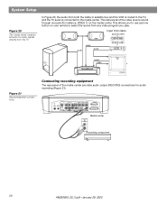
... rear panel of the video source sound through one button on the media center. audio video audio Input from both the cable or satellite box and the VCR is routed to the TV, and the TV audio is connected to use just one jack...Figure 21). VIDEO I D L 75 Ω AM FM LOOP ANTENNA ANTENNA OPTICAL R AUDIO INPUT VIDEO 2 L D AUX L VIDEO INPUT C VIDEO OUTPUT C AUDIO OUTPUT L SPEAKERS R D R S S R ACOUSTIMASS MODULE RECORD INPUT Media center L R Recording component 20 AM256950_02_V.pdf • January 29, 2002 This allows you play. System Setup Figure 20 ...
... rear panel of the video source sound through one button on the media center. audio video audio Input from both the cable or satellite box and the VCR is routed to the TV, and the TV audio is connected to use just one jack...Figure 21). VIDEO I D L 75 Ω AM FM LOOP ANTENNA ANTENNA OPTICAL R AUDIO INPUT VIDEO 2 L D AUX L VIDEO INPUT C VIDEO OUTPUT C AUDIO OUTPUT L SPEAKERS R D R S S R ACOUSTIMASS MODULE RECORD INPUT Media center L R Recording component 20 AM256950_02_V.pdf • January 29, 2002 This allows you play. System Setup Figure 20 ...
Owner's guide
Page 21
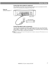
... 22). Figure 22 AUX input connections System Setup Connecting other audio components may feature a digital audio output. Use an optical digital cable or coaxial cable to the AUX inputs on the rear panel of the media center. VIDEO I D L 75 Ω AM FM LOOP ANTENNA... ANTENNA OPTICAL R AUDIO INPUT VIDEO 2 L D R D AUX L VIDEO INPUT C VIDEO AUDIO OUTPUT OUTPUT C L R S S R SPEAKERS ACOUSTIMASS MODULE Media center AUDIO OUT AUX component L R ...
... 22). Figure 22 AUX input connections System Setup Connecting other audio components may feature a digital audio output. Use an optical digital cable or coaxial cable to the AUX inputs on the rear panel of the media center. VIDEO I D L 75 Ω AM FM LOOP ANTENNA... ANTENNA OPTICAL R AUDIO INPUT VIDEO 2 L D R D AUX L VIDEO INPUT C VIDEO AUDIO OUTPUT OUTPUT C L R S S R SPEAKERS ACOUSTIMASS MODULE Media center AUDIO OUT AUX component L R ...
Owner's guide
Page 39
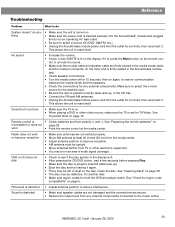
... to unmute the sound. • Make sure the module cable and speaker cable are firmly seated in the media center jacks and the...sure the TV is on the display. This allows the unit to restore communication between the media center and the speakers. • Check the connections for a minute, then reconnect it. No sound • Increase the volume. &#... Move antennas farther from TV or other video source, make sure the TV is distorted • Make sure speaker cables are not damaged and the connections are connected properly. • Move AM antenna at the media center. See ...
... to unmute the sound. • Make sure the module cable and speaker cable are firmly seated in the media center jacks and the...sure the TV is on the display. This allows the unit to restore communication between the media center and the speakers. • Check the connections for a minute, then reconnect it. No sound • Increase the volume. &#... Move antennas farther from TV or other video source, make sure the TV is distorted • Make sure speaker cables are not damaged and the connections are connected properly. • Move AM antenna at the media center. See ...
Owner's guide
Page 40
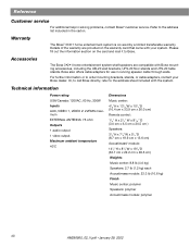
... covered by a limited transferable warranty. Bose also offers cable adapters for use in the carton. Accessories The Bose 3•2•1 home entertainment system shelf speakers are provided on the card and mail it to the address sheet included with Bose mounting accessories, including the UB-20 ...wall brackets, UFS-20 floor stands and UTS-20 table stands. Or, to call Bose directly, refer to Bose. For further information or to the address list included in running speaker cable through walls. Technical information Power rating USA/Canada: 120VAC, 60 Hz, 300W Inputs AUX, ...
... covered by a limited transferable warranty. Bose also offers cable adapters for use in the carton. Accessories The Bose 3•2•1 home entertainment system shelf speakers are provided on the card and mail it to the address sheet included with Bose mounting accessories, including the UB-20 ...wall brackets, UFS-20 floor stands and UTS-20 table stands. Or, to call Bose directly, refer to Bose. For further information or to the address list included in running speaker cable through walls. Technical information Power rating USA/Canada: 120VAC, 60 Hz, 300W Inputs AUX, ...


