
U8668 D user's manual
Page 3
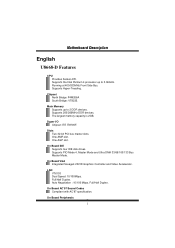
... 2D/3D Graphics Controller and Video Accelerator. Auto Negotiation : 10/100 Mbps, Full/Half Duplex. On Board Peripherals 1 MMootthheerrbbooaarrdd DDeessccrriippttiioonn English U8668-D Features CPU Provides Socket-478. Slots Two 32-bit PCI bus master slots. On Board IDE Supports four IDE disk drives. Supports PIO Mode 4, Master Mode and Ultra DMA 33/66/100/133 Bus Master Mode. Chipset North Bridge: P4M266A South Bridge: VT8235. Supports 200/266MHz DDR devices. Main Memory Supports up to 2 DDR devices. Supports the Intel Pentium 4 processor up...
... 2D/3D Graphics Controller and Video Accelerator. Auto Negotiation : 10/100 Mbps, Full/Half Duplex. On Board Peripherals 1 MMootthheerrbbooaarrdd DDeessccrriippttiioonn English U8668-D Features CPU Provides Socket-478. Slots Two 32-bit PCI bus master slots. On Board IDE Supports four IDE disk drives. Supports PIO Mode 4, Master Mode and Ultra DMA 33/66/100/133 Bus Master Mode. Chipset North Bridge: P4M266A South Bridge: VT8235. Supports 200/266MHz DDR devices. Main Memory Supports up to 2 DDR devices. Supports the Intel Pentium 4 processor up...
U8668 D user's manual
Page 4
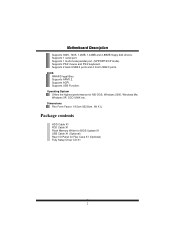
... highest performance for Flex Case X1 (Optional) Fully Setup Driver CD X1 2 MMootthheerrbbooaarrdd DDeessccrriippttiioonn Supports 360K, 720K, 1.2MB, 1.44MB and 2.88MB floppy disk drivers. Supports 2 back USB2.0 ports and 4 front USB2.0 ports. Supports ACPI. Supports USB Function. Dimensions Flex Form Factor: 19.5cm X22.8cm. (W X L) Package contents HDD Cable X1 FDD Cable X1 Flash Memory Writer for BIOS Update X1 USB Cable X1 (Optional) Rear I/O Panel for MS-DOS, Windows 2000, Windows Me, Windows XP, SCO UNIX etc. Supports APM1.2. Supports 1 serial port.
... highest performance for Flex Case X1 (Optional) Fully Setup Driver CD X1 2 MMootthheerrbbooaarrdd DDeessccrriippttiioonn Supports 360K, 720K, 1.2MB, 1.44MB and 2.88MB floppy disk drivers. Supports 2 back USB2.0 ports and 4 front USB2.0 ports. Supports ACPI. Supports USB Function. Dimensions Flex Form Factor: 19.5cm X22.8cm. (W X L) Package contents HDD Cable X1 FDD Cable X1 Flash Memory Writer for BIOS Update X1 USB Cable X1 (Optional) Rear I/O Panel for MS-DOS, Windows 2000, Windows Me, Windows XP, SCO UNIX etc. Supports APM1.2. Supports 1 serial port.
U8668 D user's manual
Page 6
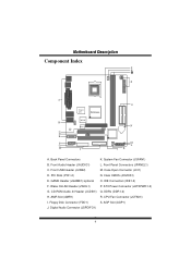
...Front USB Header (JUSB2) M. Wake OnLAN Header (JWOL1) P. Digital Audio Connector (JSPDIFO1) 4 Front Panel Connectors (JPANEL1) C. Case Open Connector (JCI1) D. GAME Header (JGAME1):optional O. DDRs (DDR1-2) H. Floppy Disk Connector (FDD1) S. AGP Slot (AGP1) J. CD-ROM Audio-In Header (JCDIN1) Q. System Fan Connector (JSFAN1) B. PCI Slots (PCI1-2) N. ATX Power Connector (JATXPWR1-2) G. Clear CMOS (JCMOS1) E. MMootthheerrbbooaarrdd DDeessccrriippttiioonn Component Index S R P A Super I/O P4M266A BIOS B Codec LAN C D JGAME1 E F G H I . IDE Connectors (IDE1...
...Front USB Header (JUSB2) M. Wake OnLAN Header (JWOL1) P. Digital Audio Connector (JSPDIFO1) 4 Front Panel Connectors (JPANEL1) C. Case Open Connector (JCI1) D. GAME Header (JGAME1):optional O. DDRs (DDR1-2) H. Floppy Disk Connector (FDD1) S. AGP Slot (AGP1) J. CD-ROM Audio-In Header (JCDIN1) Q. System Fan Connector (JSFAN1) B. PCI Slots (PCI1-2) N. ATX Power Connector (JATXPWR1-2) G. Clear CMOS (JCMOS1) E. MMootthheerrbbooaarrdd DDeessccrriippttiioonn Component Index S R P A Super I/O P4M266A BIOS B Codec LAN C D JGAME1 E F G H I . IDE Connectors (IDE1...
U8668 D user's manual
Page 7
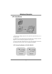
Match Pin A with the white dot/cut edge in the CPU. CPU/ System Fan Headers: JCFAN1/ JSFAN1 1 Ground 12V Sense J C FA N 1 1 Ground 12V Sense J S FA N 1 5 Press the lever down. Then Put the fan on the CPU and buckle it and put the fan's power port into the JCFAN1, then to a 90-degree angle. 2. Locate Pin A in the socket and look for the white dot or cut edge then insert the CPU. 3. Pull the lever sideways away from the socket then raise the lever up to complete the installation. MMootthheerrbbooaarrdd DDeessccrriippttiioonn CPU Installation CPU Fan CPU 1.
Match Pin A with the white dot/cut edge in the CPU. CPU/ System Fan Headers: JCFAN1/ JSFAN1 1 Ground 12V Sense J C FA N 1 1 Ground 12V Sense J S FA N 1 5 Press the lever down. Then Put the fan on the CPU and buckle it and put the fan's power port into the JCFAN1, then to a 90-degree angle. 2. Locate Pin A in the socket and look for the white dot or cut edge then insert the CPU. 3. Pull the lever sideways away from the socket then raise the lever up to complete the installation. MMootthheerrbbooaarrdd DDeessccrriippttiioonn CPU Installation CPU Fan CPU 1.
U8668 D user's manual
Page 8
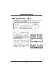
... DIMM memory modules into the socket at a 90-degree angle, then push down vertically so that it will fit into the slot in place. 6 DRAM Type: 64MB/ 128MB/ 256MB/ 512MB/ 1GB DIMM Module.(184 pin) DIMM Socket Location DDR Module Total Memory Size (MB) DDR 1 DDR 2 64MB/128MB/256MB/512MB/1GB *1 64MB/128MB/256MB/512MB/1GB *1 Max is only for DRAM configuration is...
... DIMM memory modules into the socket at a 90-degree angle, then push down vertically so that it will fit into the slot in place. 6 DRAM Type: 64MB/ 128MB/ 256MB/ 512MB/ 1GB DIMM Module.(184 pin) DIMM Socket Location DDR Module Total Memory Size (MB) DDR 1 DDR 2 64MB/128MB/256MB/512MB/1GB *1 64MB/128MB/256MB/512MB/1GB *1 Max is only for DRAM configuration is...
U8668 D user's manual
Page 9
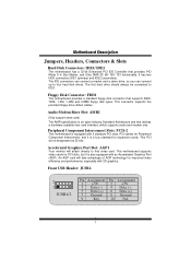
... Mode 0~4, Bus Master, and Ultra DMA 33/ 66/ 100/ 133 functionality. Accelerated Graphics Port Slot: AGP1 Your monitor will take advantage of AGP technology for expansion cards. This connector supports the provided floppy drive ribbon cables. Front USB Header: JUSB2 2 1 JUSB1/2 Pin Assignment 1 +5V 3 Data (-) 5 Data (+) 7 Ground 9 Key Pin Assignment 2 +5V 4 Data (-) 6 Data (+) 8 Ground 10 NA 7 MMootthheerrbbooaarrdd DDeessccrriippttiioonn Jumpers, Headers, Connectors & Slots Hard Disk Connectors: IDE1/ IDE2 The motherboard has a 32-bit Enhanced PCI IDE Controller that supports...
... Mode 0~4, Bus Master, and Ultra DMA 33/ 66/ 100/ 133 functionality. Accelerated Graphics Port Slot: AGP1 Your monitor will take advantage of AGP technology for expansion cards. This connector supports the provided floppy drive ribbon cables. Front USB Header: JUSB2 2 1 JUSB1/2 Pin Assignment 1 +5V 3 Data (-) 5 Data (+) 7 Ground 9 Key Pin Assignment 2 +5V 4 Data (-) 6 Data (+) 8 Ground 10 NA 7 MMootthheerrbbooaarrdd DDeessccrriippttiioonn Jumpers, Headers, Connectors & Slots Hard Disk Connectors: IDE1/ IDE2 The motherboard has a 32-bit Enhanced PCI IDE Controller that supports...

U8668 D user's manual
Page 11
... desired password or clear the CMOS data. 9 Make JCMOS1 (2-3) closed . 5. SLP ==> Sleep Button PWR_LED ==> Power LED ON/ OFF ==> Power-on Button Clear CMOS Jumper: JCMOS JCMOS Assignment Pin 1-2 on Normal Operation 1 (default) Pin 2-3 on . 6. Make JCMOS1 (1-2) closed . 3. HLED ==> Hard Driver LED RST ==> Reset Button IR ==> Infrared Conn. Let AC power on Clear CMOS 1 Data ※ Clear CMOS Procedures: 1. MMootthheerrbbooaarrdd DDeessccrriippttiioonn Front Panel Connector: JPANEL1 PWR_LED SLP ON/OFF IR 2 24 1 23 SPK (H+)L(E-)DRST IR SPK ==> Speaker Conn...
... desired password or clear the CMOS data. 9 Make JCMOS1 (2-3) closed . 5. SLP ==> Sleep Button PWR_LED ==> Power LED ON/ OFF ==> Power-on Button Clear CMOS Jumper: JCMOS JCMOS Assignment Pin 1-2 on Normal Operation 1 (default) Pin 2-3 on . 6. Make JCMOS1 (1-2) closed . 3. HLED ==> Hard Driver LED RST ==> Reset Button IR ==> Infrared Conn. Let AC power on Clear CMOS 1 Data ※ Clear CMOS Procedures: 1. MMootthheerrbbooaarrdd DDeessccrriippttiioonn Front Panel Connector: JPANEL1 PWR_LED SLP ON/OFF IR 2 24 1 23 SPK (H+)L(E-)DRST IR SPK ==> Speaker Conn...
U8668 D user's manual
Page 12
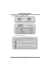
Front Panel Audio Connector/ Jumper Block Jumper Setting Configuration 1 3 5 7 9 462 10 Pin 5 and 6 Pin 9 and 10 Audio line out signals are routed to the back panel audio line out connector. 1 3 5 7 9 42 6 No jumpers Audio line out and mic in signals are 10 installed available for front panel audio connectors. 10 JF_AUDIO1 only support 2CH. MMootthheerrbbooaarrdd DDeessccrriippttiioonn Audio Subsystem: JAUDIO1/ JCDIN1 2 1 1 JAUDIO1 JCDIN1 (Front Audio Header) (CD-ROM Audio-In Header) 22 10 1 9 Pin Assignment 1 Mic In 3 Mic Power 5 RT...
Front Panel Audio Connector/ Jumper Block Jumper Setting Configuration 1 3 5 7 9 462 10 Pin 5 and 6 Pin 9 and 10 Audio line out signals are routed to the back panel audio line out connector. 1 3 5 7 9 42 6 No jumpers Audio line out and mic in signals are 10 installed available for front panel audio connectors. 10 JF_AUDIO1 only support 2CH. MMootthheerrbbooaarrdd DDeessccrriippttiioonn Audio Subsystem: JAUDIO1/ JCDIN1 2 1 1 JAUDIO1 JCDIN1 (Front Audio Header) (CD-ROM Audio-In Header) 22 10 1 9 Pin Assignment 1 Mic In 3 Mic Power 5 RT...

U8668 D user's manual
Page 14
MMootthheerrbbooaarrdd DDeessccrriippttiioonn Case Open Connector: JCI1 JCI1 1 No jumper installed Assignment Normal Operation (default) 1 Pin 1-2 on Case Open Back Panel Connectors JKBMS1 PS/2 Mouse PS/2 USB Keyboard JUSB1 JPRNT1 Parallel JUSBLAN2 LAN Line In Speaker Out Mic In COM1 JCOM1 VGA JVGA1 USB JAUDIO 12
MMootthheerrbbooaarrdd DDeessccrriippttiioonn Case Open Connector: JCI1 JCI1 1 No jumper installed Assignment Normal Operation (default) 1 Pin 1-2 on Case Open Back Panel Connectors JKBMS1 PS/2 Mouse PS/2 USB Keyboard JUSB1 JPRNT1 Parallel JUSBLAN2 LAN Line In Speaker Out Mic In COM1 JCOM1 VGA JVGA1 USB JAUDIO 12
U8668 D user's manual
Page 31
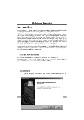
With the Overclock Manager, users can easily adjust the frequency they prefer or they can get the best CPU performance with the CPU speed are synchronically shown on the other hand, helps to install DirectX 8.1.) Installation 1. The Overvoltage Manager, on our main panel. If you use Windows XP, you can get detail descriptions about BIOS model and chipsets. The cool Hardware Monitor smartly indicates the temperatures, voltage and CPU fan speed as well...
With the Overclock Manager, users can easily adjust the frequency they prefer or they can get the best CPU performance with the CPU speed are synchronically shown on the other hand, helps to install DirectX 8.1.) Installation 1. The Overvoltage Manager, on our main panel. If you use Windows XP, you can get detail descriptions about BIOS model and chipsets. The cool Hardware Monitor smartly indicates the temperatures, voltage and CPU fan speed as well...
U8668 D user's manual
Page 33
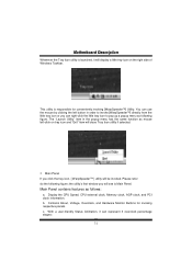
... is Main Panel. Display the CPU Speed, CPU external clock, Memory clock, AGP clock, and PCI clock information. c. MMootthheerrbbooaarrdd DDeessccrriippttiioonn Whenever the Tray Icon utility is launched, it can represent 3 overclock percentage stages: 31 You can right-click the little tray icon to pop up a popup menu as follows: a. the utility's first window you click the tray icon, [ WarpSpeeder™ ] utility will close Tray Icon utility if selected. 2. b. With a user...
... is Main Panel. Display the CPU Speed, CPU external clock, Memory clock, AGP clock, and PCI clock information. c. MMootthheerrbbooaarrdd DDeessccrriippttiioonn Whenever the Tray Icon utility is launched, it can represent 3 overclock percentage stages: 31 You can right-click the little tray icon to pop up a popup menu as follows: a. the utility's first window you click the tray icon, [ WarpSpeeder™ ] utility will close Tray Icon utility if selected. 2. b. With a user...

U8668 D user's manual
Page 34
In this panel, you can decide to get the best performance of overclocking, we recommend you want to increase CPU core voltage and Memory voltage or not. The default setting is "No". If you click the option "Yes". 32 MMootthheerrbbooaarrdd DDeessccrriippttiioonn Man walking => overclock percentage from 100% ~ 110 % Panther running => overclock percentage from 110% ~ 120% Car racing => overclock percentage from 120% ~ above 3. Voltage Panel Click the Voltage button in Main Panel, the button will be highlighted and the Voltage Panel will slide out to up as the following figure.
In this panel, you can decide to get the best performance of overclocking, we recommend you want to increase CPU core voltage and Memory voltage or not. The default setting is "No". If you click the option "Yes". 32 MMootthheerrbbooaarrdd DDeessccrriippttiioonn Man walking => overclock percentage from 100% ~ 110 % Panther running => overclock percentage from 110% ~ 120% Car racing => overclock percentage from 120% ~ above 3. Voltage Panel Click the Voltage button in Main Panel, the button will be highlighted and the Voltage Panel will slide out to up as the following figure.
U8668 D user's manual
Page 36
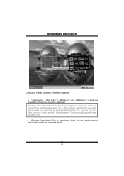
... a fail-safe reboot. 34 Or, you can just click Auto overclock button and let [ WarpSpeeder™ ] automatically gets the best result for you overclock by click the Verify button. "Recovery Dialog button": Pop up the following dialog. MMootthheerrbbooaarrdd DDeessccrriippttiioonn Overclock Panel contains the these features: a. "-3MHz button", "-1MHz button", "+1MHz button", and "+3MHz button": provide user the ability to do real-time overclock adjustment. Warning: Manually overclock is...
... a fail-safe reboot. 34 Or, you can just click Auto overclock button and let [ WarpSpeeder™ ] automatically gets the best result for you overclock by click the Verify button. "Recovery Dialog button": Pop up the following dialog. MMootthheerrbbooaarrdd DDeessccrriippttiioonn Overclock Panel contains the these features: a. "-3MHz button", "-1MHz button", "+1MHz button", and "+3MHz button": provide user the ability to do real-time overclock adjustment. Warning: Manually overclock is...

U8668 D user's manual
Page 37
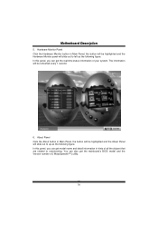
...-safe rebooting. "Auto-overclock button": User can click this button and [ WarpSpeeder™ ] will set the best and stable performance and frequency automatically. [ WarpSpeeder™ ] utility will do fail-safe reboot by using Watchdog function. If the testing fail, system will execute a series of testing until system fail. "Verify button": User can click this button and [ WarpSpeeder™ ] will restore to the hardware default setting or load the...
...-safe rebooting. "Auto-overclock button": User can click this button and [ WarpSpeeder™ ] will set the best and stable performance and frequency automatically. [ WarpSpeeder™ ] utility will do fail-safe reboot by using Watchdog function. If the testing fail, system will execute a series of testing until system fail. "Verify button": User can click this button and [ WarpSpeeder™ ] will restore to the hardware default setting or load the...
U8668 D user's manual
Page 38
... [ WarpSpeeder™ ] utility. 36 In this panel, you can also get model name and detail information in Main Panel, the button will be refreshed every 1 second. 6. You can get the mainboard's BIOS model and the Version number of your system. About Panel Click the About button in Main Panel, the button will be highlighted and the About Panel will be highlighted and the Hardware Monitor panel will slide...
... [ WarpSpeeder™ ] utility. 36 In this panel, you can also get model name and detail information in Main Panel, the button will be refreshed every 1 second. 6. You can get the mainboard's BIOS model and the Version number of your system. About Panel Click the About button in Main Panel, the button will be highlighted and the About Panel will be highlighted and the Hardware Monitor panel will slide...

U8668 D user's manual
Page 39
If one chipset is not on board, the correlative button in Main panel will be disabled, but will not interfere other panels' functions. This property can make [ WarpSpeeder™ ] utility more robust. 37 MMootthheerrbbooaarrdd DDeessccrriippttiioonn Note: Because the overclock, overvoltage, and hardware monitor features are controlled by several separate chipset, [ WarpSpeeder™ ] divide these features to separate panels.
If one chipset is not on board, the correlative button in Main panel will be disabled, but will not interfere other panels' functions. This property can make [ WarpSpeeder™ ] utility more robust. 37 MMootthheerrbbooaarrdd DDeessccrriippttiioonn Note: Because the overclock, overvoltage, and hardware monitor features are controlled by several separate chipset, [ WarpSpeeder™ ] divide these features to separate panels.
U8668 D user's manual
Page 40
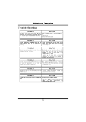
... * Replace cable * Contact technical support PROBABLE SOLUTION System inoperative. Hard disk can * Back up the hard drive is extremely important. PROBABLE SOLUTION Screen message says "Invalid Configuration" or * Review system's equipment . PROBABLE SOLUTION Cannot boot system after installing second hard * Set master/slave jumpers correctly. Call drive manufacturers for compatibility with other drives. 38 board. Indicator light on keyboard does not turn on both ends are lit, hard drive is securely plugged in setup. Keyboard lights are on, * Using...
... * Replace cable * Contact technical support PROBABLE SOLUTION System inoperative. Hard disk can * Back up the hard drive is extremely important. PROBABLE SOLUTION Screen message says "Invalid Configuration" or * Review system's equipment . PROBABLE SOLUTION Cannot boot system after installing second hard * Set master/slave jumpers correctly. Call drive manufacturers for compatibility with other drives. 38 board. Indicator light on keyboard does not turn on both ends are lit, hard drive is securely plugged in setup. Keyboard lights are on, * Using...

U8668 D BIOS setup guide
Page 3
... the numeric value or make changes Decrease the numeric value or make changes Increase the numeric value or make changes Decrease the numeric value or make changes General help on Setup navigation keys Load previous values from CMOS Load the optimized defaults Save all the CMOS changes and exit Keystroke Up arrow Down arrow Left arrow Right arrow Esc Move Enter PgUp key PgDn key + Key -
... the numeric value or make changes Decrease the numeric value or make changes Increase the numeric value or make changes Decrease the numeric value or make changes General help on Setup navigation keys Load previous values from CMOS Load the optimized defaults Save all the CMOS changes and exit Keystroke Up arrow Down arrow Left arrow Right arrow Esc Move Enter PgUp key PgDn key + Key -
U8668 D BIOS setup guide
Page 8
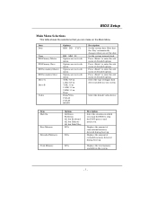
... in its sub menu. Set the system internal clock. Displays the amount of conventional memory detected during boot up . Options are in its sub menu. Press to stop the POST process and notify you. Select the default video device. Options are in which you set the date. Item Halt On Base Memory Extended Memory Total Memory Options All Errors No Errors All, but Keyboard All, but Diskette All, but Disk/ Key N/A N/A N/A Description Select the...
... in its sub menu. Set the system internal clock. Displays the amount of conventional memory detected during boot up . Options are in its sub menu. Press to stop the POST process and notify you. Select the default video device. Options are in which you set the date. Item Halt On Base Memory Extended Memory Total Memory Options All Errors No Errors All, but Keyboard All, but Diskette All, but Disk/ Key N/A N/A N/A Description Select the...
U8668 D BIOS setup guide
Page 32
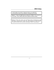
Method 2: Press the key and Power button simultaneously, after that you are selected is not functioning, there are two methods of booting-up the system according to FSB of the processor. All the CMOS data will boot-up the system. If unfortunately, the system's frequency that keep-on pressing the key until the power-on screen showed. Method 1: Clear the CMOS data by setting the JCMOS1 ((2-3) closed)) as defaults setting. This action will be loaded as "ON" status.
Method 2: Press the key and Power button simultaneously, after that you are selected is not functioning, there are two methods of booting-up the system according to FSB of the processor. All the CMOS data will boot-up the system. If unfortunately, the system's frequency that keep-on pressing the key until the power-on screen showed. Method 1: Clear the CMOS data by setting the JCMOS1 ((2-3) closed)) as defaults setting. This action will be loaded as "ON" status.


