Setup Manual
Page 1
...changed without notice and we will not occur in a particular installation. Duplication of this user's manual is subject to be responsible for any purpose. TP35D2-A7 Setup Manual FCC Information and Copyright This equipment has been tested and found in this publication and to make... designed to provide reasonable protection against harmful interference in a residential installation. Further the vendor reserves the right to revise this user's manual. This equipment generates, uses, and can radiate radio frequency energy and, if not installed and used in writing. These limits are...
...changed without notice and we will not occur in a particular installation. Duplication of this user's manual is subject to be responsible for any purpose. TP35D2-A7 Setup Manual FCC Information and Copyright This equipment has been tested and found in this publication and to make... designed to provide reasonable protection against harmful interference in a residential installation. Further the vendor reserves the right to revise this user's manual. This equipment generates, uses, and can radiate radio frequency energy and, if not installed and used in writing. These limits are...
Setup Manual
Page 3
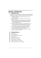
... the computer from power outlet before operation. „ Before you for ATX Case X 1 User's Manual X 1 Fully Setup Driver CD X 1 FDD Cable X 1 (optional) USB 2.0 Cable X1 (optional) S/PDIF out Cable X 1 (optional) Serial ATA Power Cable X 1 (optional) 1 CHAPTER 1: INTRODUCTION TP35D2-A7 1.1 BEFORE YOU START Thank you take the motherboard out from anti-static bag, ground...
... the computer from power outlet before operation. „ Before you for ATX Case X 1 User's Manual X 1 Fully Setup Driver CD X 1 FDD Cable X 1 (optional) USB 2.0 Cable X1 (optional) S/PDIF out Cable X 1 (optional) Serial ATA Power Cable X 1 (optional) 1 CHAPTER 1: INTRODUCTION TP35D2-A7 1.1 BEFORE YOU START Thank you take the motherboard out from anti-static bag, ground...
Setup Manual
Page 4
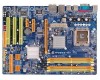
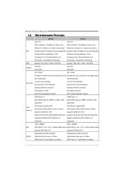
... ATA Controller SATA 2 Data transfer rates up to 3.0 Gb/s. SATA Version 2.0 specification compliant SATA Version 2.0 specification compliant 2 I /O functionality. Data transfer rates up to 3.0 Gb/s. Motherboard Manual 1.3 MOTHERBOARD FEATURES Ver 5.x Ver 6.x LGA 775 LGA 775 Intel Core2Duo / Core2Quad / Celeron 4xx / Intel Core2Duo / Core2Quad / Celeron 4xx / Pentium D / Pentium 4 / Celeron D processor Pentium D / Pentium 4 / Celeron...
... ATA Controller SATA 2 Data transfer rates up to 3.0 Gb/s. SATA Version 2.0 specification compliant SATA Version 2.0 specification compliant 2 I /O functionality. Data transfer rates up to 3.0 Gb/s. Motherboard Manual 1.3 MOTHERBOARD FEATURES Ver 5.x Ver 6.x LGA 775 LGA 775 Intel Core2Duo / Core2Quad / Celeron 4xx / Intel Core2Duo / Core2Quad / Celeron 4xx / Pentium D / Pentium 4 / Celeron D processor Pentium D / Pentium 4 / Celeron...
Setup Manual
Page 6
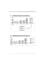
Motherboard Manual 1.4 REAR PANEL CONNECTORS (FOR VER 5.X) PS/2 M ou se LA N Audio Jack PS/ 2 Ke ybo ar d COM1 USBX2 USBX2 USBX2 Center Rear Si de Line In Line Out Mic In 1.5 REAR PANEL CONNECTORS (FOR VER 6.X) PS/2 M ou se LAN PS/ 2 Ke ybo ar d COM1 USBX2 USBX2 USBX2 Line In/ Su rr oun d Line Out Mic In 1/ Bass/ Center 4
Motherboard Manual 1.4 REAR PANEL CONNECTORS (FOR VER 5.X) PS/2 M ou se LA N Audio Jack PS/ 2 Ke ybo ar d COM1 USBX2 USBX2 USBX2 Center Rear Si de Line In Line Out Mic In 1.5 REAR PANEL CONNECTORS (FOR VER 6.X) PS/2 M ou se LAN PS/ 2 Ke ybo ar d COM1 USBX2 USBX2 USBX2 Line In/ Su rr oun d Line Out Mic In 1/ Bass/ Center 4
Setup Manual
Page 8
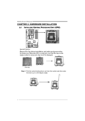
Motherboard Manual CHAPTER 2: HARDWARE INSTALLATION 2.1 INSTALLING CENTRAL PROCESSING UNIT (CPU) Special Notice: Remove Pin Cap before installation, and make good preservation for future use. Pin Cap Step 1: Pull the socket locking lever out from the socket and then raise the lever up to ensure pin legs won't be damaged. When the CPU is removed, cover the Pin Cap on the empty socket to a 90-degree angle. 6
Motherboard Manual CHAPTER 2: HARDWARE INSTALLATION 2.1 INSTALLING CENTRAL PROCESSING UNIT (CPU) Special Notice: Remove Pin Cap before installation, and make good preservation for future use. Pin Cap Step 1: Pull the socket locking lever out from the socket and then raise the lever up to ensure pin legs won't be damaged. When the CPU is removed, cover the Pin Cap on the empty socket to a 90-degree angle. 6
Setup Manual
Page 10
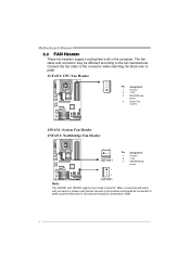
... the black wire is Ground and should be different according to the fan manufacturer. The fan cable and connector may be connected to pin#1. Motherboard Manual 2.2 FAN HEADERS These fan headers support cooling-fans built in the computer.
... the black wire is Ground and should be different according to the fan manufacturer. The fan cable and connector may be connected to pin#1. Motherboard Manual 2.2 FAN HEADERS These fan headers support cooling-fans built in the computer.
Setup Manual
Page 12
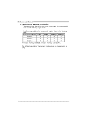
Dual Channel Status DDR2_A1 DDR2_A2 DDR2_B1 DDR2_B2 Enabled O X O X Enabled X O X O Enabled O O O O (O means memory installed, X means memory not installed.) The DRAM bus width of the memory module must meet the following requirements: Install memory module of the motherboard, the memory module must be the same (x8 or x16) 10 Motherboard Manual C. Dual Channel Memory installation To trigger the Dual Channel function of the same density in pairs, shown in the following table.
Dual Channel Status DDR2_A1 DDR2_A2 DDR2_B1 DDR2_B2 Enabled O X O X Enabled X O X O Enabled O O O O (O means memory installed, X means memory not installed.) The DRAM bus width of the memory module must meet the following requirements: Install memory module of the motherboard, the memory module must be the same (x8 or x16) 10 Motherboard Manual C. Dual Channel Memory installation To trigger the Dual Channel function of the same density in pairs, shown in the following table.
Setup Manual
Page 14
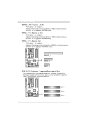
... Interconnect, and it is a bus standard for an aggregate of 500MB/s totally. Maximum theoretical realized bandwidth of 1GB/s simultaneously per direction, for expansion cards. Motherboard Manual PEX16_1: PCI-Express x16 Slot - PEX16_1 PEX4_1 PEX1_1 PCI1~PCI3: Peripheral Component Interconnect Slots This motherboard is designated as 32 bits.
... Interconnect, and it is a bus standard for an aggregate of 500MB/s totally. Maximum theoretical realized bandwidth of 1GB/s simultaneously per direction, for expansion cards. Motherboard Manual PEX16_1: PCI-Express x16 Slot - PEX16_1 PEX4_1 PEX1_1 PCI1~PCI3: Peripheral Component Interconnect Slots This motherboard is designated as 32 bits.
Setup Manual
Page 16
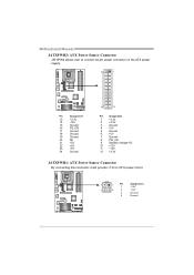
Motherboard Manual JATXPWR2: ATX Power Source Connector JATXPW2 allows user to connect 24-pin power connector on the ATX power supply. 13 1 Pin Assignment 13 +3.3V 14 -...
Motherboard Manual JATXPWR2: ATX Power Source Connector JATXPW2 allows user to connect 24-pin power connector on the ATX power supply. 13 1 Pin Assignment 13 +3.3V 14 -...
Setup Manual
Page 18
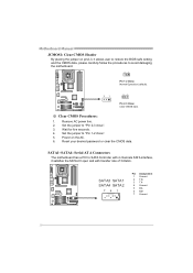
... 4 channels SATA interface, it allows user to restore the BIOS safe setting and the CMOS data, please carefully follow the procedures to "Pin 2-3 close ". 5. Motherboard Manual JCMOS1: Clear CMOS Header By placing the jumper on the AC. 6.
... 4 channels SATA interface, it allows user to restore the BIOS safe setting and the CMOS data, please carefully follow the procedures to "Pin 2-3 close ". 5. Motherboard Manual JCMOS1: Clear CMOS Header By placing the jumper on the AC. 6.
Setup Manual
Page 20
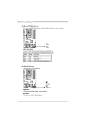
On-Board Buttons There are 2 LED indicators on the motherboard to the table below for different messages: LED1 LED2 Message ON ON Normal ON OFF Memory Error OFF ON VGA Error OFF OFF Abnormal: CPU / Chipset error. RSTSW2 PWRSW1 PWRSW1: This is an on-board Reset button. 18 LED2 LED1 and LED2: LED1 These 2 LED indicate system power on diagnostics. RSTSW2: This is an on-board Power Switch button. Motherboard Manual On-Board LED Indicators There are 2 on-board buttons. Please refer to show system status.
On-Board Buttons There are 2 LED indicators on the motherboard to the table below for different messages: LED1 LED2 Message ON ON Normal ON OFF Memory Error OFF ON VGA Error OFF OFF Abnormal: CPU / Chipset error. RSTSW2 PWRSW1 PWRSW1: This is an on-board Reset button. 18 LED2 LED1 and LED2: LED1 These 2 LED indicate system power on diagnostics. RSTSW2: This is an on-board Power Switch button. Motherboard Manual On-Board LED Indicators There are 2 on-board buttons. Please refer to show system status.
Setup Manual
Page 22
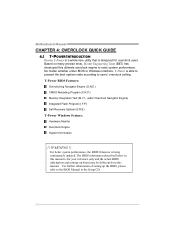
The BIOS information described below in the Setup CD. 20 Based on board may be different from this manual. T-Power BIOS Features: Overclocking Navigator Engine (O.N.E.) CMOS Reloading Program (C.R.P.) Memory Integration Test (M.I .F.P.) Self Recovery System (S.R.S) T-Power Windows... to users' overclock setting. For better system performance, the BIOS firmware is being continuously updated. Motherboard Manual CHAPTER 4: OVERCLOCK QUICK GUIDE 4.1 T-POWER INTRODUCTION Biostar T-Power is a whole new utility that is designed for your reference only and the actual BIOS information...
The BIOS information described below in the Setup CD. 20 Based on board may be different from this manual. T-Power BIOS Features: Overclocking Navigator Engine (O.N.E.) CMOS Reloading Program (C.R.P.) Memory Integration Test (M.I .F.P.) Self Recovery System (S.R.S) T-Power Windows... to users' overclock setting. For better system performance, the BIOS firmware is being continuously updated. Motherboard Manual CHAPTER 4: OVERCLOCK QUICK GUIDE 4.1 T-POWER INTRODUCTION Biostar T-Power is a whole new utility that is designed for your reference only and the actual BIOS information...
Setup Manual
Page 23
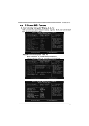
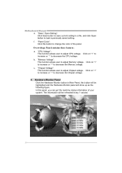
Manual Overclock System (M.O.S.) MOS is designed for both Elite and Casual overclockers. It allows users to customize personal overclock settings. 21 TP35D2-A7 4.2 T-POWER BIOS FEATURE A. Overclocking Navigator Engine (O.N.E.): ONE provides two powerful overclocking engines: MOS and AOS for experienced overclock users.
Manual Overclock System (M.O.S.) MOS is designed for both Elite and Casual overclockers. It allows users to customize personal overclock settings. 21 TP35D2-A7 4.2 T-POWER BIOS FEATURE A. Overclocking Navigator Engine (O.N.E.): ONE provides two powerful overclocking engines: MOS and AOS for experienced overclock users.
Setup Manual
Page 24
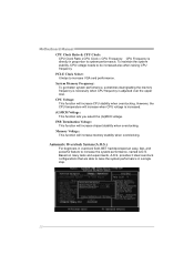
..., the CPU temperature will increase CPU stability when overclocking. CPU Voltage: This function will increase when CPU voltage is adjusted over the upper limit. Motherboard Manual CPU Clock Ratio & CPU Clock: CPU Clock Ratio x CPU Clock = CPU Frequency.
..., the CPU temperature will increase CPU stability when overclocking. CPU Voltage: This function will increase when CPU voltage is adjusted over the upper limit. Motherboard Manual CPU Clock Ratio & CPU Clock: CPU Clock Ratio x CPU Clock = CPU Frequency.
Setup Manual
Page 26
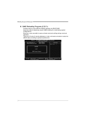
CMOS Reloading Program (C.R.P.): It allows users to personal preference. 24 Users are able to name the CMOS data according to save an ideal overclock setting during overclock operation. There are 50 sets of record addresses in total, and users are able to save different CMOS settings into BIOS-ROM. Moreover, users are able to reload any saved CMOS setting for customizing system configurations. Motherboard Manual B.
CMOS Reloading Program (C.R.P.): It allows users to personal preference. 24 Users are able to name the CMOS data according to save an ideal overclock setting during overclock operation. There are 50 sets of record addresses in total, and users are able to save different CMOS settings into BIOS-ROM. Moreover, users are able to reload any saved CMOS setting for customizing system configurations. Motherboard Manual B.
Setup Manual
Page 28
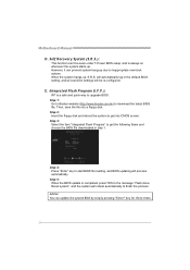
Step 1: Go to Biostar website (http://www.biostar.com.tw) to get the following frame and choose the BIOS file downloaded in the default BIOS setting, and all overclock settings will process automatically. Advise: You can 't be re-configured. Motherboard Manual D. However, it can prevent system hang-up , S.R.S. When the system hangs up due...
Step 1: Go to Biostar website (http://www.biostar.com.tw) to get the following frame and choose the BIOS file downloaded in the default BIOS setting, and all overclock settings will process automatically. Advise: You can 't be re-configured. Motherboard Manual D. However, it can prevent system hang-up , S.R.S. When the system hangs up due...
Setup Manual
Page 30
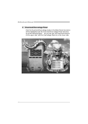
As you can see, the Overclock Panel is on the upper side, and the Overvoltage Panel is on the lower side. 28 Motherboard Manual 3. Overclock/Overvoltage Panel Click the Overclock/Overvoltage button in the Main Panel, the button will be highlighted and the Overclock/Overvoltage Panel will show up as the following figure.
As you can see, the Overclock Panel is on the upper side, and the Overvoltage Panel is on the lower side. 28 Motherboard Manual 3. Overclock/Overvoltage Panel Click the Overclock/Overvoltage button in the Main Panel, the button will be highlighted and the Overclock/Overvoltage Panel will show up as the following figure.
Setup Manual
Page 31
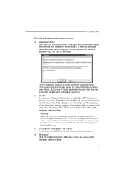
...and T-Utility will be saved into system registry. Then T-Utility will set the best and stable performance and frequency automatically. Warning: Manually overclock is potentially dangerous, especially when the overclocking percentage is ok, then the current frequency will proceed a testing for you. b....reboot by click the Verify button. After reboot, the T-Utility will do real-time overclock adjustment. TP35D2-A7 Overclock Panel contains these features: a. "Verify": If you use the "Manual Adjust" bar to adjust the CPU frequency, then you that the system may become unstable, click...
...and T-Utility will be saved into system registry. Then T-Utility will set the best and stable performance and frequency automatically. Warning: Manually overclock is potentially dangerous, especially when the overclocking percentage is ok, then the current frequency will proceed a testing for you. b....reboot by click the Verify button. After reboot, the T-Utility will do real-time overclock adjustment. TP35D2-A7 Overclock Panel contains these features: a. "Verify": If you use the "Manual Adjust" bar to adjust the CPU frequency, then you that the system may become unstable, click...
Setup Manual
Page 32
... click Open button to decrease the CPU voltage. "Panel Color": Click this panel, you can get the real-time status information of the panel. Motherboard Manual e. Click on "+" to increase or "-" to load a previously saved setting. "Memory Voltage": This function allows user to decrease the Chipset voltage. 4. c. The information will be...
... click Open button to decrease the CPU voltage. "Panel Color": Click this panel, you can get the real-time status information of the panel. Motherboard Manual e. Click on "+" to increase or "-" to load a previously saved setting. "Memory Voltage": This function allows user to decrease the Chipset voltage. 4. c. The information will be...
Setup Manual
Page 34
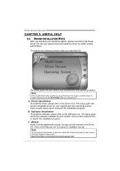
... to browse for better system performance. Please download the latest version of Acrobat Reader software from the paperback manual, we also provide manual in the Driver CD. Driver Installation To install the driver, please click on the Software icon. Note: You will list ...the software available for your motherboard and operating system. C. Motherboard Manual CHAPTER 5: USEFUL HELP 5.1 DRIVER INSTALLATION NOTE After you installed your operating system, please insert the Fully Setup Driver CD into your optical drive...
... to browse for better system performance. Please download the latest version of Acrobat Reader software from the paperback manual, we also provide manual in the Driver CD. Driver Installation To install the driver, please click on the Software icon. Note: You will list ...the software available for your motherboard and operating system. C. Motherboard Manual CHAPTER 5: USEFUL HELP 5.1 DRIVER INSTALLATION NOTE After you installed your operating system, please insert the Fully Setup Driver CD into your optical drive...

