
Setup Manual
Page 1
TForce 6100 AM2 Setup Manual FCC Information and Copyright This equipment has been tested and found in this user's manual. Duplication of the FCC Rules. This equipment generates, ...
TForce 6100 AM2 Setup Manual FCC Information and Copyright This equipment has been tested and found in this user's manual. Duplication of the FCC Rules. This equipment generates, ...
Setup Manual
Page 3
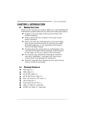
... equipment. „ Keep the computer from anti-static bag, ground yourself properly by touching any unfastened small parts inside the case after installation. CHAPTER 1: INTRODUCTION TForce 6100 AM2 1.1 BEFORE YOU START Thank you take the motherboard out from dangerous area, such as heat source, humid air and water. 1.2 PACKAGE CHECKLIST FDD Cable X 1 HDD...
... equipment. „ Keep the computer from anti-static bag, ground yourself properly by touching any unfastened small parts inside the case after installation. CHAPTER 1: INTRODUCTION TForce 6100 AM2 1.1 BEFORE YOU START Thank you take the motherboard out from dangerous area, such as heat source, humid air and water. 1.2 PACKAGE CHECKLIST FDD Cable X 1 HDD...
Setup Manual
Page 5
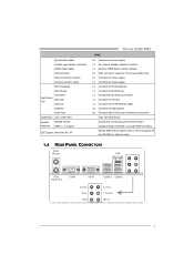
...USB Port Audio Jack Board Size 244 x 244 (mm) Special Features NVIDIA nTunes RAID 0 / 1 support OS Support Windows 2K / XP TForce 6100 AM2 SPEC x3 System Fan Power supply x1 For chassis intruder detection function x1 Restore CMOS data to factory default x2 Each connector supports 2 front ... Board Tuning and monitoring system performance Supports Raid 0 and Raid 1 through SATA connector. x1 Connects to RJ-45 ethernet cable x4 Connects to monitor. Biostar Reserves the right to add or remove support for any OS With or without notice. 1.4 REAR PANEL CONNECTORS PS/2 Mo u se LAN P S/2 ...
...USB Port Audio Jack Board Size 244 x 244 (mm) Special Features NVIDIA nTunes RAID 0 / 1 support OS Support Windows 2K / XP TForce 6100 AM2 SPEC x3 System Fan Power supply x1 For chassis intruder detection function x1 Restore CMOS data to factory default x2 Each connector supports 2 front ... Board Tuning and monitoring system performance Supports Raid 0 and Raid 1 through SATA connector. x1 Connects to RJ-45 ethernet cable x4 Connects to monitor. Biostar Reserves the right to add or remove support for any OS With or without notice. 1.4 REAR PANEL CONNECTORS PS/2 Mo u se LAN P S/2 ...
Setup Manual
Page 7
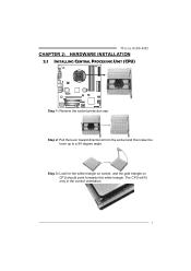
TForce 6100 AM2 CHAPTER 2: HARDWARE INSTALLATION 2.1 INSTALLING CENTRAL PROCESSING UNIT (CPU) Step 1: Remove the socket protection cap. Step 2: Pull the lever toward direction A from the socket and then raise the lever up to a 90-degree angle. The CPU will fit only in the correct orientation. 5 Step 3: Look for the white triangle on socket, and the gold triangle on CPU should point forwards this white triangle.
TForce 6100 AM2 CHAPTER 2: HARDWARE INSTALLATION 2.1 INSTALLING CENTRAL PROCESSING UNIT (CPU) Step 1: Remove the socket protection cap. Step 2: Pull the lever toward direction A from the socket and then raise the lever up to a 90-degree angle. The CPU will fit only in the correct orientation. 5 Step 3: Look for the white triangle on socket, and the gold triangle on CPU should point forwards this white triangle.

Setup Manual
Page 9
JSFAN1 /JSFAN2: System Fan Header TForce 6100 AM2 1 J S FA N 1 JSFAN1 Pin Assignment 1 Ground 2 Smart Fan Control 3 FAN RPM rate sense 1 JSFAN2 JSFAN2 Pin Assignment 1 Ground 2 +12V 3 Ground JNFAN1: North Bridge Fan Header Pin ...
JSFAN1 /JSFAN2: System Fan Header TForce 6100 AM2 1 J S FA N 1 JSFAN1 Pin Assignment 1 Ground 2 Smart Fan Control 3 FAN RPM rate sense 1 JSFAN2 JSFAN2 Pin Assignment 1 Ground 2 +12V 3 Ground JNFAN1: North Bridge Fan Header Pin ...
Setup Manual
Page 11
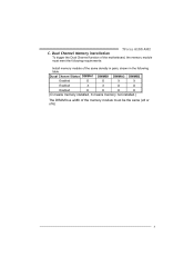
Duual Channel Status DIMMA1 DIMMB1 DIMMA2 DIMMB2 Enabled O O X X Enabled X X O O Enabled O O O O (O means memory installed, X means memory not installed.) The DRAM bus width of the same density in pairs, shown in the following table. TForce 6100 AM2 C. Dual Channel Memory installation To trigger the Dual Channel function of the motherboard, the memory module must meet the following requirements: Install memory module of the memory module must be the same (x8 or x16) 9
Duual Channel Status DIMMA1 DIMMB1 DIMMA2 DIMMB2 Enabled O O X X Enabled X X O O Enabled O O O O (O means memory installed, X means memory not installed.) The DRAM bus width of the same density in pairs, shown in the following table. TForce 6100 AM2 C. Dual Channel Memory installation To trigger the Dual Channel function of the motherboard, the memory module must meet the following requirements: Install memory module of the memory module must be the same (x8 or x16) 9
Setup Manual
Page 13
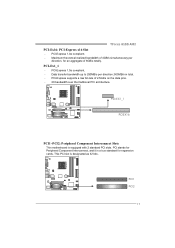
..., and it is a bus standard for an aggregate of 2.5Gb/s on the data pins. - 2X bandwidth over the traditional PCI architecture. PCI-Express 1.0a compliant. - TForce 6100 AM2 PCI-Ex16: PCI-Express x16 Slot - PCI1 PCI2 11 PCI-Express supports a raw bit-rate of 8GB/s totally. P CI -E X1_1 PC IE X16 PCI1~PCI2...
..., and it is a bus standard for an aggregate of 2.5Gb/s on the data pins. - 2X bandwidth over the traditional PCI architecture. PCI-Express 1.0a compliant. - TForce 6100 AM2 PCI-Ex16: PCI-Express x16 Slot - PCI1 PCI2 11 PCI-Express supports a raw bit-rate of 8GB/s totally. P CI -E X1_1 PC IE X16 PCI1~PCI2...
Setup Manual
Page 15
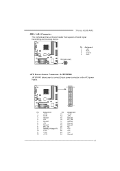
... Ground 7 Ground 19 Ground 8 PW_OK 20 NC 9 Standby Voltage+5V 21 +5V 10 +12V 22 +5V 11 +12V 23 +5V 12 +3.3V 24 Ground 13 TForce 6100 AM2 JIR1: IrDA Connector The motherboard has a Infrared header that supports infrared signal transmitting and receiving device.
... Ground 7 Ground 19 Ground 8 PW_OK 20 NC 9 Standby Voltage+5V 21 +5V 10 +12V 22 +5V 11 +12V 23 +5V 12 +3.3V 24 Ground 13 TForce 6100 AM2 JIR1: IrDA Connector The motherboard has a Infrared header that supports infrared signal transmitting and receiving device.

Setup Manual
Page 17
JUSBV2: +5V for USB ports at JUSBLAN1. TForce 6100 AM2 JUSBV1/JUSBV2: Power Source Headers for USB Ports Pin 1-2 Close: JUSBV1: +5V for USB ports at front panel (JUSB2/JUSB3). JUSBV2: USB ports at JUSBLAN1 are powered by +5V standby voltage. Pin 2-3 Close: JUSBV1: USB ports at front panel (JUSB2/JUSB3) are powered by +5V standby voltage. 1 JUSBV1 1 JUSBV2 1 1 3 3 Pin 1-2 close 1 1 3 3 Pin 2-3 close Note: In order to support this function "Power-On system via USB device," "JUSBV1/ JUSBV2" jumper cap should be placed on Pin 2-3 individually. 15
JUSBV2: +5V for USB ports at JUSBLAN1. TForce 6100 AM2 JUSBV1/JUSBV2: Power Source Headers for USB Ports Pin 1-2 Close: JUSBV1: +5V for USB ports at front panel (JUSB2/JUSB3). JUSBV2: USB ports at JUSBLAN1 are powered by +5V standby voltage. Pin 2-3 Close: JUSBV1: USB ports at front panel (JUSB2/JUSB3) are powered by +5V standby voltage. 1 JUSBV1 1 JUSBV2 1 1 3 3 Pin 1-2 close 1 1 3 3 Pin 2-3 close Note: In order to support this function "Power-On system via USB device," "JUSBV1/ JUSBV2" jumper cap should be placed on Pin 2-3 individually. 15
Setup Manual
Page 19
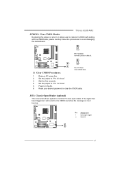
... signal has been triggered, it allows user to restore the BIOS safe setting and the CMOS data, please carefully follow the procedures to "Pin 2-3 close ". 5. TForce 6100 AM2 JCMOS1: Clear CMOS Header By placing the jumper on pin2-3, it will record to "Pin 1-2 close ". 3. Set the jumper to avoid damaging the motherboard. 1 3 Pin...
... signal has been triggered, it allows user to restore the BIOS safe setting and the CMOS data, please carefully follow the procedures to "Pin 2-3 close ". 5. TForce 6100 AM2 JCMOS1: Clear CMOS Header By placing the jumper on pin2-3, it will record to "Pin 1-2 close ". 3. Set the jumper to avoid damaging the motherboard. 1 3 Pin...
Setup Manual
Page 21
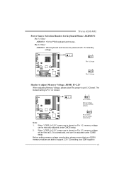
..., and can be adjusted under CMOS setup. 2. When "JDDR_II>2.2V" jumper cap is placed on Pin 1-2, memory voltage can 't be manually adjusted under COMS setup. TForce 6100 AM2 Power Source Selection Headers for Keyboard/Mouse: JKBMSV1 Pin 1-2 Close: JKBMSV1: +5V for PS/2 keyboard and mouse。 Pin 2-3 Close: JKBMSV1: PS/2 keyboard and mouse...
..., and can be adjusted under CMOS setup. 2. When "JDDR_II>2.2V" jumper cap is placed on Pin 1-2, memory voltage can 't be manually adjusted under COMS setup. TForce 6100 AM2 Power Source Selection Headers for Keyboard/Mouse: JKBMSV1 Pin 1-2 Close: JKBMSV1: +5V for PS/2 keyboard and mouse。 Pin 2-3 Close: JKBMSV1: PS/2 keyboard and mouse...

Setup Manual
Page 23
Pin Assignment 1 -Strobe 2 -ALF 3 Data 0 4 -Error 5 Data 1 6 -Init 7 Data 2 8 -Scltin 9 Data 3 10 Ground 11 Data 4 12 Ground 13 Data 5 Pin Assignment 14 Ground 15 Data 6 16 Ground 17 Data 7 18 Ground 19 -ACK 20 Ground 21 Busy 22 Ground 23 PE 24 Ground 25 SCLT 21 TForce 6100 AM2 JPRNT1: Printer Port Connector This header allows you to connector printer on the PC.
Pin Assignment 1 -Strobe 2 -ALF 3 Data 0 4 -Error 5 Data 1 6 -Init 7 Data 2 8 -Scltin 9 Data 3 10 Ground 11 Data 4 12 Ground 13 Data 5 Pin Assignment 14 Ground 15 Data 6 16 Ground 17 Data 7 18 Ground 19 -ACK 20 Ground 21 Busy 22 Ground 23 PE 24 Ground 25 SCLT 21 TForce 6100 AM2 JPRNT1: Printer Port Connector This header allows you to connector printer on the PC.

Setup Manual
Page 25
... (backup) copy of the data can be applied for the storage space of one drive fail, the controller switches to download NVIDIA nForce Tutorial Flash. TForce 6100 AM2 RAID 1: Every read and write is corrupted or becomes unavailable because of a hardware failure. RAID 1 provides a hot-standby copy of data if the active volume...
... (backup) copy of the data can be applied for the storage space of one drive fail, the controller switches to download NVIDIA nForce Tutorial Flash. TForce 6100 AM2 RAID 1: Every read and write is corrupted or becomes unavailable because of a hardware failure. RAID 1 provides a hot-standby copy of data if the active volume...
Setup Manual
Page 27
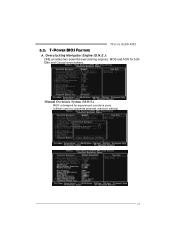
It allows users to customize personal overclock settings. 25 TForce 6100 AM2 5.2: T-POWER BIOS FEATURE A. Manual Overclock System (M.O.S.) MOS is designed for both Elite and Casual overclockers. Overclocking Navigator Engine (O.N.E.): ONE provides two powerful overclocking engines: MOS and AOS for experienced overclock users.
It allows users to customize personal overclock settings. 25 TForce 6100 AM2 5.2: T-POWER BIOS FEATURE A. Manual Overclock System (M.O.S.) MOS is designed for both Elite and Casual overclockers. Overclocking Navigator Engine (O.N.E.): ONE provides two powerful overclocking engines: MOS and AOS for experienced overclock users.
Setup Manual
Page 29
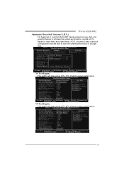
TForce 6100 AM2 Automatic Overclock System (A.O.S.) For beginners in overclock field, BET had developed an easy, fast, and powerful feature to raise the system performance in a single step. V8 Tech Engine: This setting will raise about 15%~25% of whole system performance. Based on many tests and experiments, A.O.S. provides 3 ideal overclock configurations that are able to increase the system performance, named A.O.S. V6 Tech Engine: This setting will raise about 10%~15% of whole system performance. 27
TForce 6100 AM2 Automatic Overclock System (A.O.S.) For beginners in overclock field, BET had developed an easy, fast, and powerful feature to raise the system performance in a single step. V8 Tech Engine: This setting will raise about 15%~25% of whole system performance. Based on many tests and experiments, A.O.S. provides 3 ideal overclock configurations that are able to increase the system performance, named A.O.S. V6 Tech Engine: This setting will raise about 10%~15% of whole system performance. 27
Setup Manual
Page 31
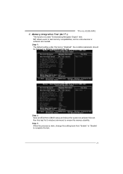
TForce 6100 AM2 C. Memory Integration Test (M.I.T.): This function is under this test for 5 minutes (minimum) to complete the test. 29 Run this item is done, change the setting ...
TForce 6100 AM2 C. Memory Integration Test (M.I.T.): This function is under this test for 5 minutes (minimum) to complete the test. 29 Run this item is done, change the setting ...
Setup Manual
Page 33
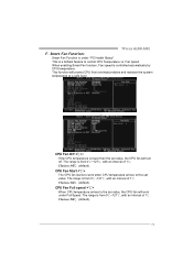
...;. The range is lower than the set value, the CPU fan will work when CPU temperature arrives to the set value. Choices: 32℃ (default). TForce 6100 AM2 F. Smart Fan Function: Smart Fan Function is from 0℃~127℃, with an interval of 1℃. CPU Fan Start The CPU fan starts to work...
...;. The range is lower than the set value, the CPU fan will work when CPU temperature arrives to the set value. Choices: 32℃ (default). TForce 6100 AM2 F. Smart Fan Function: Smart Fan Function is from 0℃~127℃, with an interval of 1℃. CPU Fan Start The CPU fan starts to work...

Setup Manual
Page 35
... in the system tray. 33 Hide Click on this item to hide this item to pop-up . The program will be taken by a waveform diagram. TForce 6100 AM2 5.3 T-POWER WINDOWS FEATURE A.Hardware Monitor: T-Power Hardware monitor allows users to monitor system voltage, temperature and fan speed accordingly. All the monitoring items are illustrated...
... in the system tray. 33 Hide Click on this item to hide this item to pop-up . The program will be taken by a waveform diagram. TForce 6100 AM2 5.3 T-POWER WINDOWS FEATURE A.Hardware Monitor: T-Power Hardware monitor allows users to monitor system voltage, temperature and fan speed accordingly. All the monitoring items are illustrated...

Setup Manual
Page 37
... set value, the status line will change into a red warning line, and a warning sound will change to monitor the CPU operating voltage. CPU/Battery Voltage TForce 6100 AM2 i.
... set value, the status line will change into a red warning line, and a warning sound will change to monitor the CPU operating voltage. CPU/Battery Voltage TForce 6100 AM2 i.
Setup Manual
Page 39
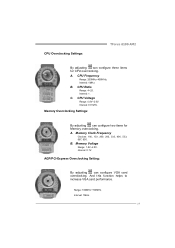
...: 100MHz~150MHz. CPU Ratio Range: 4~25. Interval: 0.0125V. B. AGP/PCI-Express Overclocking Setting: By adjusting can configure two items for CPU overclocking. CPU Overclocking Settings: TForce 6100 AM2 By adjusting can configure three items for Memory overclocking. CPU Frequency Range: 200MHz~450MHz. A.
...: 100MHz~150MHz. CPU Ratio Range: 4~25. Interval: 0.0125V. B. AGP/PCI-Express Overclocking Setting: By adjusting can configure two items for CPU overclocking. CPU Overclocking Settings: TForce 6100 AM2 By adjusting can configure three items for Memory overclocking. CPU Frequency Range: 200MHz~450MHz. A.


