Setup Manual
Page 1
... right to revise this publication and to make changes to the contents here without first obtaining the vendor's approval in this user's manual. The content of the FCC Rules. This equipment generates, uses, and can radiate radio frequency energy and, if not installed and...any mistakes found in writing. There is no representations or warranties with the instructions, may cause harmful interference to radio communications. TF520 A2+/TF560 A2+ Setup Manual FCC Information and Copyright This equipment has been tested and found to comply with the limits of a Class B digital device, pursuant...
... right to revise this publication and to make changes to the contents here without first obtaining the vendor's approval in this user's manual. The content of the FCC Rules. This equipment generates, uses, and can radiate radio frequency energy and, if not installed and...any mistakes found in writing. There is no representations or warranties with the instructions, may cause harmful interference to radio communications. TF520 A2+/TF560 A2+ Setup Manual FCC Information and Copyright This equipment has been tested and found to comply with the limits of a Class B digital device, pursuant...
Setup Manual
Page 3
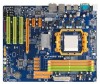
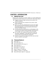
... computer from power outlet before operation. „ Before you for ATX Case X 1 User's Manual X 1 Fully Setup Driver CD X 1 FDD Cable X 1 (optional) USB 2.0 Cable X1 (optional) S/PDIF out Cable X 1 (optional) Serial ATA Power Cable X 1 (optional) 1 CHAPTER 1: INTRODUCTION TF520 A2+/TF560 A2+ 1.1 BEFORE YOU START Thank you take the motherboard out from dangerous area, such as...
... computer from power outlet before operation. „ Before you for ATX Case X 1 User's Manual X 1 Fully Setup Driver CD X 1 FDD Cable X 1 (optional) USB 2.0 Cable X1 (optional) S/PDIF out Cable X 1 (optional) Serial ATA Power Cable X 1 (optional) 1 CHAPTER 1: INTRODUCTION TF520 A2+/TF560 A2+ 1.1 BEFORE YOU START Thank you take the motherboard out from dangerous area, such as...
Setup Manual
Page 4
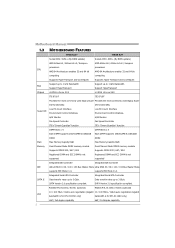
... negotiation (Gigabit 10 / 100 Mb/s / 1Gb/s auto negotiation (Gigabit bandwidth is for RTL 8110SC only) Half / Full duplex capability Half / Full duplex capability Motherboard Manual 1.3 MOTHERBOARD FEATURES TF520 A2+ TF560 A2+ Socket AM2 / AM2+ (By BIOS update) Socket AM2 / AM2+ (By BIOS update) AMD Athlon 64 / Athlon 64 x2 / Sempron AMD Athlon 64 / Athlon...
... negotiation (Gigabit 10 / 100 Mb/s / 1Gb/s auto negotiation (Gigabit bandwidth is for RTL 8110SC only) Half / Full duplex capability Half / Full duplex capability Motherboard Manual 1.3 MOTHERBOARD FEATURES TF520 A2+ TF560 A2+ Socket AM2 / AM2+ (By BIOS update) Socket AM2 / AM2+ (By BIOS update) AMD Athlon 64 / Athlon 64 x2 / Sempron AMD Athlon 64 / Athlon...
Setup Manual
Page 6
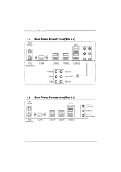
Motherboard Manual 1.4 REAR PANEL CONNECTORS (VER 5.X) PS/2 Mouse LAN PS/2 Keyboard COM1 USBX2 USBX2 USBX2 Center Rear Side Line In Line Out Mic In 1.5 REAR PANEL CONNECTORS (VER 6.X) PS/2 Mouse LA N PS/ 2 Keyboard COM1 USBX2 USBX2 USBX2 Line In/ Surround Line Out Mic I n 1/ Bass/ Center 4
Motherboard Manual 1.4 REAR PANEL CONNECTORS (VER 5.X) PS/2 Mouse LAN PS/2 Keyboard COM1 USBX2 USBX2 USBX2 Center Rear Side Line In Line Out Mic In 1.5 REAR PANEL CONNECTORS (VER 6.X) PS/2 Mouse LA N PS/ 2 Keyboard COM1 USBX2 USBX2 USBX2 Line In/ Surround Line Out Mic I n 1/ Bass/ Center 4

Setup Manual
Page 8
Step 3: Look for the white triangle on socket, and the gold triangle on CPU should point forwards this white triangle. Step 2: Pull the lever toward direction A from the socket and then raise the lever up to a 90-degree angle. The CPU will fit only in the correct orientation. 6 Motherboard Manual CHAPTER 2: HARDWARE INSTALLATION 2.1 INSTALLING CENTRAL PROCESSING UNIT (CPU) Step 1: Remove the socket protection cap.
Step 3: Look for the white triangle on socket, and the gold triangle on CPU should point forwards this white triangle. Step 2: Pull the lever toward direction A from the socket and then raise the lever up to a 90-degree angle. The CPU will fit only in the correct orientation. 6 Motherboard Manual CHAPTER 2: HARDWARE INSTALLATION 2.1 INSTALLING CENTRAL PROCESSING UNIT (CPU) Step 1: Remove the socket protection cap.

Setup Manual
Page 10
Motherboard Manual 2.2 FAN HEADERS These fan headers support cooling-fans built in the computer. JCFAN1: CPU Fan Header 1 4 Pin Assignment 1 Ground 2 +12V 3 FAN RPM rate sense 4 Smart ...
Motherboard Manual 2.2 FAN HEADERS These fan headers support cooling-fans built in the computer. JCFAN1: CPU Fan Header 1 4 Pin Assignment 1 Ground 2 +12V 3 FAN RPM rate sense 4 Smart ...

Setup Manual
Page 12
Motherboard Manual C. Dual Channel Memory installation To trigger the Dual Channel function of the same density in pairs, shown in the following table. Duual Channel Status DIMMA1 DIMMB1 DIMMA2 DIMMB2 Enabled O O X X Enabled X X O O Enabled O O O O (O means memory installed, X means memory not installed.) The DRAM bus width of the memory module must meet the following requirements: Install memory module of the motherboard, the memory module must be the same (x8 or x16) 10
Motherboard Manual C. Dual Channel Memory installation To trigger the Dual Channel function of the same density in pairs, shown in the following table. Duual Channel Status DIMMA1 DIMMB1 DIMMA2 DIMMB2 Enabled O O X X Enabled X X O O Enabled O O O O (O means memory installed, X means memory not installed.) The DRAM bus width of the memory module must meet the following requirements: Install memory module of the motherboard, the memory module must be the same (x8 or x16) 10

Setup Manual
Page 14
... This motherboard is designated as 32 bits. PCI stands for Peripheral Component Interconnect, and it is a bus standard for an aggregate of 8GB/s totally. Motherboard Manual PEX16-1: PCI-Express x16 Slot - PCI1 PCI2 PCI3 12 Data transfer bandwidth up to 250MB/s per direction, for expansion cards. This PCI slot is equipped...
... This motherboard is designated as 32 bits. PCI stands for Peripheral Component Interconnect, and it is a bus standard for an aggregate of 8GB/s totally. Motherboard Manual PEX16-1: PCI-Express x16 Slot - PCI1 PCI2 PCI3 12 Data transfer bandwidth up to 250MB/s per direction, for expansion cards. This PCI slot is equipped...

Setup Manual
Page 16
Pin Assignment 1 +3.3V 2 +3.3V 3 Ground 4 +5V 5 Ground 6 +5V 12 24 7 Ground 8 PW_OK 9 Standby Voltage +5V 10 +12V 11 +12V 12 +3.3V 13 +3.3V 14 -12V 15 Ground 16 PS-ON 1 13 17 Ground 18 Ground 19 Ground 20 NC 21 +5V 22 +5V 23 +5V 24 Ground JATXPWR2: ATX Power Source Connector By connecting this connector, it will provide +12V to connect 24-pin power connector on the ATX power supply. Motherboard Manual JATXPWR1: ATX Power Source Connector This connector allows user to CPU power circuit. 32 4 1 Pin Assignment 1 +12V 2 +12V 3 Ground 4 Ground 14
Pin Assignment 1 +3.3V 2 +3.3V 3 Ground 4 +5V 5 Ground 6 +5V 12 24 7 Ground 8 PW_OK 9 Standby Voltage +5V 10 +12V 11 +12V 12 +3.3V 13 +3.3V 14 -12V 15 Ground 16 PS-ON 1 13 17 Ground 18 Ground 19 Ground 20 NC 21 +5V 22 +5V 23 +5V 24 Ground JATXPWR2: ATX Power Source Connector By connecting this connector, it will provide +12V to connect 24-pin power connector on the ATX power supply. Motherboard Manual JATXPWR1: ATX Power Source Connector This connector allows user to CPU power circuit. 32 4 1 Pin Assignment 1 +12V 2 +12V 3 Ground 4 Ground 14

Setup Manual
Page 18
... setting and the CMOS data, please carefully follow the procedures to "Pin 1-2 close ". 3. Set the jumper to SATA Controller with transfer rate of 3.0Gb/s. Motherboard Manual SATA1~SATA4: Serial ATA Connectors The motherboard has a PCI to "Pin 2-3 close ". 5.
... setting and the CMOS data, please carefully follow the procedures to "Pin 1-2 close ". 3. Set the jumper to SATA Controller with transfer rate of 3.0Gb/s. Motherboard Manual SATA1~SATA4: Serial ATA Connectors The motherboard has a PCI to "Pin 2-3 close ". 5.

Setup Manual
Page 20
Pin Assignment 1 1 +12V 2 Ground 3 Ground 4 VCC 4 On-Board LED Indicators There are 2 LED indicators on diagnostics. Motherboard Manual JATXPWR3: Auxiliary Power for Graphics This connector is an auxiliary power connection for the graphics card provides better graphics performance. Exclusive power for graphics cards. ...
Pin Assignment 1 1 +12V 2 Ground 3 Ground 4 VCC 4 On-Board LED Indicators There are 2 LED indicators on diagnostics. Motherboard Manual JATXPWR3: Auxiliary Power for Graphics This connector is an auxiliary power connection for the graphics card provides better graphics performance. Exclusive power for graphics cards. ...

Setup Manual
Page 22
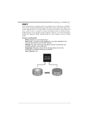
... a disk striping scheme that does not require fault tolerance. Benefits: provides increased data throughput, especially for mirroring data. It breaks up to 6 or 8. Motherboard Manual CHAPTER 4: NVIDIA RAID FUNCTIONS 4.1 OPERATION SYSTEM z Supports Windows XP Home/Professional Edition, and Windows 2000 Professional. 4.2 RAID ARRAYS NVRAID supports the following types of disk...
... a disk striping scheme that does not require fault tolerance. Benefits: provides increased data throughput, especially for mirroring data. It breaks up to 6 or 8. Motherboard Manual CHAPTER 4: NVIDIA RAID FUNCTIONS 4.1 OPERATION SYSTEM z Supports Windows XP Home/Professional Edition, and Windows 2000 Professional. 4.2 RAID ARRAYS NVRAID supports the following types of disk...
Setup Manual
Page 23
...minimal capacity. Benefits: Provides 100% data redundancy. Should one drive. Block 1 Block 2 Block 3 Block 1 Block 2 Block 3 21 TF520 A2+/TF560 A2+ RAID 1: Every read and write is impaired during drive rebuilds. Fault Tolerance: Yes. RAID 1 provides a hot-standby copy of data if the... the controller switches to the other drive. Drawbacks: Requires 2 drives for small databases or any other application that eliminates tedious manual backups to more expensive and less reliable media. RAID techniques can reside on the same disk or on a second redundant drive in ...
...minimal capacity. Benefits: Provides 100% data redundancy. Should one drive. Block 1 Block 2 Block 3 Block 1 Block 2 Block 3 21 TF520 A2+/TF560 A2+ RAID 1: Every read and write is impaired during drive rebuilds. Fault Tolerance: Yes. RAID 1 provides a hot-standby copy of data if the... the controller switches to the other drive. Drawbacks: Requires 2 drives for small databases or any other application that eliminates tedious manual backups to more expensive and less reliable media. RAID techniques can reside on the same disk or on a second redundant drive in ...

Setup Manual
Page 24
Motherboard Manual RAID 0+1: RAID 0 drives can be simultaneously used with other RAID levels in a RAID 0+1 solution for improved performance plus resiliency. Block 1 Block 3 Block 5 Block 2 Block 4 Block 6 ...
Motherboard Manual RAID 0+1: RAID 0 drives can be simultaneously used with other RAID levels in a RAID 0+1 solution for improved performance plus resiliency. Block 1 Block 3 Block 5 Block 2 Block 4 Block 6 ...

Setup Manual
Page 26
... below in the Setup CD. 24 WARNING !! For further information of setting up the BIOS, please refer to the BIOS Manual in this manual is for overclock users. For better system performance, the BIOS firmware is being continuously updated. No matter whether under PC Health... or Windows interface, T-Power is able to present the best system state according to raise system performance. Motherboard Manual CHAPTER 5: OVERCLOCK QUICK GUIDE 5.1 T-POWER INTRODUCTION Biostar T-Power is a whole new utility that is designed for your reference only and the actual BIOS information and settings...
... below in the Setup CD. 24 WARNING !! For further information of setting up the BIOS, please refer to the BIOS Manual in this manual is for overclock users. For better system performance, the BIOS firmware is being continuously updated. No matter whether under PC Health... or Windows interface, T-Power is able to present the best system state according to raise system performance. Motherboard Manual CHAPTER 5: OVERCLOCK QUICK GUIDE 5.1 T-POWER INTRODUCTION Biostar T-Power is a whole new utility that is designed for your reference only and the actual BIOS information and settings...
Setup Manual
Page 27
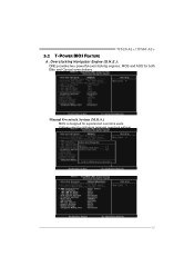
Overclocking Navigator Engine (O.N.E.): ONE provides two powerful overclocking engines: MOS and AOS for experienced overclock users. TF520 A2+/TF560 A2+ 5.2 T-POWER BIOS FEATURE A. It allows users to customize personal overclock settings. 25 Manual Overclock System (M.O.S.) MOS is designed for both Elite and Casual overclockers.
Overclocking Navigator Engine (O.N.E.): ONE provides two powerful overclocking engines: MOS and AOS for experienced overclock users. TF520 A2+/TF560 A2+ 5.2 T-POWER BIOS FEATURE A. It allows users to customize personal overclock settings. 25 Manual Overclock System (M.O.S.) MOS is designed for both Elite and Casual overclockers.

Setup Manual
Page 28
... stability when overclocking. Memory Voltage: This function will increase when CPU voltage is directly in proportion to be increased also when raising CPU frequency. Motherboard Manual DRAM Configuration: Enter this option when proceeding overclocking. Please disable this option when proceeding overclocking. PCIE Clock: It helps to northbridge chipset. NPT Fid Control...
... stability when overclocking. Memory Voltage: This function will increase when CPU voltage is directly in proportion to be increased also when raising CPU frequency. Motherboard Manual DRAM Configuration: Enter this option when proceeding overclocking. Please disable this option when proceeding overclocking. PCIE Clock: It helps to northbridge chipset. NPT Fid Control...

Setup Manual
Page 30
... configurations. Notices: 1. Not all types of whole system performance. the difference will raise about 25%~30% of AMD CPU perform above overclock setting ideally; Motherboard Manual V12 Tech Engine: This setting will be based on the selected CPU model.
... configurations. Notices: 1. Not all types of whole system performance. the difference will raise about 25%~30% of AMD CPU perform above overclock setting ideally; Motherboard Manual V12 Tech Engine: This setting will be based on the selected CPU model.

Setup Manual
Page 32
... BIOS update is a safe and quick way to get into a floppy disk. Step 1: Go to Biostar website (http://www.biostar.com.tw) to start BIOS file loading, and BIOS updating will be seen under T-Power BIOS setup; Motherboard Manual D. and is always on whenever the system starts up , S.R.S. Step 3: Select the item "Integrated...
... BIOS update is a safe and quick way to get into a floppy disk. Step 1: Go to Biostar website (http://www.biostar.com.tw) to start BIOS file loading, and BIOS updating will be seen under T-Power BIOS setup; Motherboard Manual D. and is always on whenever the system starts up , S.R.S. Step 3: Select the item "Integrated...

Setup Manual
Page 34
The range is from 0~127, with an interval of 1. 32 The range is from 0℃~127℃, with an interval of 1℃. Start PWM Value When CPU temperature arrives to the set value, the CPU fan will work under Full Speed. CPU Fan Full speed When CPU temperature arrives to the set value. The range is from 0℃~127℃, with an interval of 1℃. Motherboard Manual CPU Fan Start The CPU fan starts to work when CPU temperature arrives to this set value, the CPU fan will work under Smart Fan Function mode.
The range is from 0~127, with an interval of 1. 32 The range is from 0℃~127℃, with an interval of 1℃. Start PWM Value When CPU temperature arrives to the set value, the CPU fan will work under Full Speed. CPU Fan Full speed When CPU temperature arrives to the set value. The range is from 0℃~127℃, with an interval of 1℃. Motherboard Manual CPU Fan Start The CPU fan starts to work when CPU temperature arrives to this set value, the CPU fan will work under Smart Fan Function mode.

