Setup Manual
Page 2
... (CPU 6 2.2 FAN Headers 8 2.3 Installing System Memory 9 2.4 Connectors and Slots 11 Chapter 3: Headers & Jumpers Setup 16 3.1 How to Setup Jumpers 16 3.2 Detail Settings 16 Chapter 4: (Hybrid) CrossFireX Function 21 4.1 CrossFireX Requirements 21 4.2 CrossFireX Installation 21 4.3 Hybrid CrossFireX Requirements 22 4.4 Hybrid CrossFireX Installation 22 4.5 Operation Modes Supporting List 23 Chapter 5: RAID Functions 24 5.1 Operating System 24 5.2 Raid Arrays 24 5.3 How RAID Works 24 Chapter 6: T-Series BIOS & Software 28 6.1 T-Series BIOS 28...
... (CPU 6 2.2 FAN Headers 8 2.3 Installing System Memory 9 2.4 Connectors and Slots 11 Chapter 3: Headers & Jumpers Setup 16 3.1 How to Setup Jumpers 16 3.2 Detail Settings 16 Chapter 4: (Hybrid) CrossFireX Function 21 4.1 CrossFireX Requirements 21 4.2 CrossFireX Installation 21 4.3 Hybrid CrossFireX Requirements 22 4.4 Hybrid CrossFireX Installation 22 4.5 Operation Modes Supporting List 23 Chapter 5: RAID Functions 24 5.1 Operating System 24 5.2 Raid Arrays 24 5.3 How RAID Works 24 Chapter 6: T-Series BIOS & Software 28 6.1 T-Series BIOS 28...
Setup Manual
Page 5
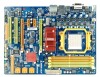
... cards PCI Express Gen2 x1 Slot x2 Supports PCI-E Gen2 x1 expansion cards Floppy Connector x1 Each connector supports 2 Floppy drives IDE Connector x1 Each connector supports 2 IDE device SATA Connector x6 Each connector supports 1 SATA devices Front Panel Connector x1 Supports front panel facilities Front Audio Connector x1 Supports front panel audio function CD-in Connector On Board S/PDIF out Connector Connectors CPU Fan Header x1 Supports CD audio-in function x1 Supports digital audio out function x1 CPU Fan power supply (with Smart Fan function) System Fan Header...
... cards PCI Express Gen2 x1 Slot x2 Supports PCI-E Gen2 x1 expansion cards Floppy Connector x1 Each connector supports 2 Floppy drives IDE Connector x1 Each connector supports 2 IDE device SATA Connector x6 Each connector supports 1 SATA devices Front Panel Connector x1 Supports front panel facilities Front Audio Connector x1 Supports front panel audio function CD-in Connector On Board S/PDIF out Connector Connectors CPU Fan Header x1 Supports CD audio-in function x1 Supports digital audio out function x1 CPU Fan power supply (with Smart Fan function) System Fan Header...
Setup Manual
Page 18
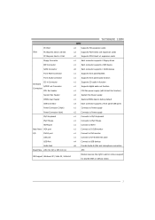
...: Front Panel Header This 16-pin connector includes Power-on button 16 It allows user to set up jumpers. PWR_LE D On/Off ++- 9 16 1 +- 8 SPK RST HLED Pin Assignment 1 +5V 2 N/A 3 N/A 4 Speaker 5 HDD LED (+) 6 HDD LED (-) 7 Ground 8 Reset control Function Pin 9 Speaker 10 Connector 11 12 Hard drive 13 LED 14 Reset button 15 16 Assignment N/A N/A N/A Power LED (+) Power LED (+) Power LED (-) Power button Ground Function N/A N/A Power LED Power-on , Reset, HDD LED, Power LED, and speaker connection. When the jumper cap is placed on pins, the jumper is...
...: Front Panel Header This 16-pin connector includes Power-on button 16 It allows user to set up jumpers. PWR_LE D On/Off ++- 9 16 1 +- 8 SPK RST HLED Pin Assignment 1 +5V 2 N/A 3 N/A 4 Speaker 5 HDD LED (+) 6 HDD LED (-) 7 Ground 8 Reset control Function Pin 9 Speaker 10 Connector 11 12 Hard drive 13 LED 14 Reset button 15 16 Assignment N/A N/A N/A Power LED (+) Power LED (+) Power LED (-) Power button Ground Function N/A N/A Power LED Power-on , Reset, HDD LED, Power LED, and speaker connection. When the jumper cap is placed on pins, the jumper is...
Setup Manual
Page 23
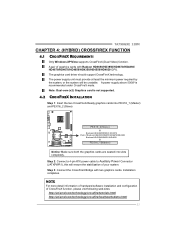
....amd.com/technology/crossfire/tutorials.html http://ati.amd.com/technology/crossfire/howitworksdemo.html 21 Note: Dual-core (x2) Graphics card is recommended under CrossFireX mode. TA790GXE 128M CHAPTER 4: (HYBRID) CROSSFIREX FUNCTION 4.1 CROSSFIREX REQUIREMENTS Only Windows XP/Vista supports CrossFireX (Dual Video) function. Step 2: Connect a 4-pin ATX power cable to Auxiliary Power Connector (JATXPWR1), this will be unstable. NOTE For more detail information of hardware/software installation and configuration of graphics cards with two graphics cards. The graphics card driver...
....amd.com/technology/crossfire/tutorials.html http://ati.amd.com/technology/crossfire/howitworksdemo.html 21 Note: Dual-core (x2) Graphics card is recommended under CrossFireX mode. TA790GXE 128M CHAPTER 4: (HYBRID) CROSSFIREX FUNCTION 4.1 CROSSFIREX REQUIREMENTS Only Windows XP/Vista supports CrossFireX (Dual Video) function. Step 2: Connect a 4-pin ATX power cable to Auxiliary Power Connector (JATXPWR1), this will be unstable. NOTE For more detail information of hardware/software installation and configuration of graphics cards with two graphics cards. The graphics card driver...
Setup Manual
Page 24
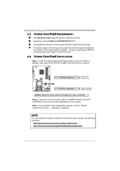
... web-sites: http://game.amd.com/us-en/crossfirex_hybrid.aspx http://ati.amd.com/technology/hybridgraphics/index.html 22 Step 2: Connect a 4-pin ATX power cable to Auxiliary Power Connector (AUXPWR1), this will be unstable. A graphics card with Radeon HD3450/HD3470 GPU. NOTE For more detail information of your system. The graphics card driver should support Hybrid CrossFireX technology. Motherboard Manual 4.3 HYBRID CROSSFIREX REQUIREMENTS Only Windows Vista supports Hybrid CrossFireX function. PEX16...
... web-sites: http://game.amd.com/us-en/crossfirex_hybrid.aspx http://ati.amd.com/technology/hybridgraphics/index.html 22 Step 2: Connect a 4-pin ATX power cable to Auxiliary Power Connector (AUXPWR1), this will be unstable. A graphics card with Radeon HD3450/HD3470 GPU. NOTE For more detail information of your system. The graphics card driver should support Hybrid CrossFireX technology. Motherboard Manual 4.3 HYBRID CROSSFIREX REQUIREMENTS Only Windows Vista supports Hybrid CrossFireX function. PEX16...
Setup Manual
Page 30
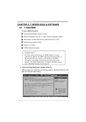
... Auto OverClock System [V6-Tech Engine] Manual OverClock System CPU/HT Reference Clock (MHz) [200] CPU Configuration [Auto] > G.P.U Phase Control > CPU Tuning > Clock Control > Voltage Configuation > DRAM Timing Configuration > Memory Configuration Integrated Memory Test [Disabled] Options Normal Automate OverClock Manual OverClock Select Screen Select Item +- Main Advanced BIOS SETUP UTILITY PCIPnP Boot Chipset T-Series Exit T-Series Settings WARNING: Setting wrong values in below in the Setup CD. For better system performance, the BIOS firmware...
... Auto OverClock System [V6-Tech Engine] Manual OverClock System CPU/HT Reference Clock (MHz) [200] CPU Configuration [Auto] > G.P.U Phase Control > CPU Tuning > Clock Control > Voltage Configuation > DRAM Timing Configuration > Memory Configuration Integrated Memory Test [Disabled] Options Normal Automate OverClock Manual OverClock Select Screen Select Item +- Main Advanced BIOS SETUP UTILITY PCIPnP Boot Chipset T-Series Exit T-Series Settings WARNING: Setting wrong values in below in the Setup CD. For better system performance, the BIOS firmware...
Setup Manual
Page 34
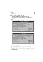
... Control > CPU Tuning > Clock Control > Voltage Configuation > DRAM Timing Configuration > Memory Configuration Integrated Memory Test [Disabled] Options Enabled Disabled Select Screen Select Item +- Step 2 Save and Exit from "Enable" to "Disable" to test memory compatibilities, and no extra devices or software are needed. MIT allows users to complete the test. 32 Change Option F1 General Help F10 Save and Exit ESC Exit Main vxx.xx (C)Copyright 1985-200x, American Megatrends, Inc. ↓ BIOS SETUP UTILITY Advanced PCIPnP Boot Chipset T-Series Exit T-Series Settings...
... Control > CPU Tuning > Clock Control > Voltage Configuation > DRAM Timing Configuration > Memory Configuration Integrated Memory Test [Disabled] Options Enabled Disabled Select Screen Select Item +- Step 2 Save and Exit from "Enable" to "Disable" to test memory compatibilities, and no extra devices or software are needed. MIT allows users to complete the test. 32 Change Option F1 General Help F10 Save and Exit ESC Exit Main vxx.xx (C)Copyright 1985-200x, American Megatrends, Inc. ↓ BIOS SETUP UTILITY Advanced PCIPnP Boot Chipset T-Series Exit T-Series Settings...
Setup Manual
Page 36
...function can prevent system hang-up due to control CPU/System Temperature vs. This is always on whenever the system starts up , S.R.S. When enabling Smart Fan function, Fan speed is under BIOS setup; E. Main Advanced BIOS SETUP UTILITY PCIPnP Boot Chipset T-Series Exit Advanced Settings WARNING: Setting wrong values in the default BIOS setting, and all overclock settings will protect CPU/System from overheat problem and maintain the system temperature at a safe level. Smart Fan Function Smart Fan Function is controlled automatically by CPU/System temperature.
...function can prevent system hang-up due to control CPU/System Temperature vs. This is always on whenever the system starts up , S.R.S. When enabling Smart Fan function, Fan speed is under BIOS setup; E. Main Advanced BIOS SETUP UTILITY PCIPnP Boot Chipset T-Series Exit Advanced Settings WARNING: Setting wrong values in the default BIOS setting, and all overclock settings will protect CPU/System from overheat problem and maintain the system temperature at a safe level. Smart Fan Function Smart Fan Function is controlled automatically by CPU/System temperature.
Setup Manual
Page 37
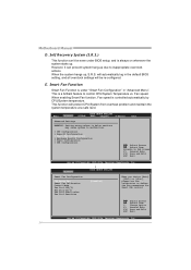
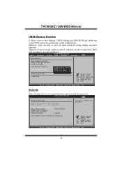
... different CMOS settings into BIOS-ROM. F. Moreover, users are able to the set value, the CPU/System fan will work when CPU/System temperature arrives to personal preference. Main Advanced PCIPnP Exit Options Save Changes and Exit Discard Changes and Exit Discard Changes Load Optimal Defaults CMOS Backup Function Security Settings > Security BIOS SETUP UTILITY Boot Chipset T-Series Exit CMOS Backup Func CMOS Data Reload CMOS Data Save Select Screen Select Item EnterGo to reload any saved CMOS setting for customizing system configurations. Fan...
... different CMOS settings into BIOS-ROM. F. Moreover, users are able to the set value, the CPU/System fan will work when CPU/System temperature arrives to personal preference. Main Advanced PCIPnP Exit Options Save Changes and Exit Discard Changes and Exit Discard Changes Load Optimal Defaults CMOS Backup Function Security Settings > Security BIOS SETUP UTILITY Boot Chipset T-Series Exit CMOS Backup Func CMOS Data Reload CMOS Data Save Select Screen Select Item EnterGo to reload any saved CMOS setting for customizing system configurations. Fan...

Setup Manual
Page 47
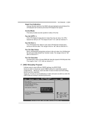
... to enter BIOS setup. While the system boots up and the full screen logo shows, press key to reboot. For better performance, the software is completed. Online Update is being continuously updated. The information and pictures described above about the T-Series software are for AMI BIOS only) Automatically download and update the latest BIOS via internet; The actual information and settings on the Online Update button, the utility will...
... to enter BIOS setup. While the system boots up and the full screen logo shows, press key to reboot. For better performance, the software is completed. Online Update is being continuously updated. The information and pictures described above about the T-Series software are for AMI BIOS only) Automatically download and update the latest BIOS via internet; The actual information and settings on the Online Update button, the utility will...
Setup Manual
Page 50
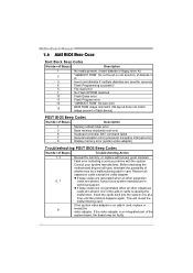
... 7 cards are used for recovery 4 Flash Programming successful 5 File read error 7 No Flash EPROM detected 10 Flash Erase error 11 Flash Program error 12 "AMIBOOT.ROM" file size error 13 BIOS ROM image mismatch (file layout does not match image present in flash device) POST BIOS Beep Codes Number of Beeps Description 1 Memory refresh timer error 3 Base memory read/write test error 6 Keyboard controller BAT command failed 7 General exception error (processor exception interrupt error) 8 Display memory error (system video adapter) Troubleshooting POST BIOS Beep Codes...
... 7 cards are used for recovery 4 Flash Programming successful 5 File read error 7 No Flash EPROM detected 10 Flash Erase error 11 Flash Program error 12 "AMIBOOT.ROM" file size error 13 BIOS ROM image mismatch (file layout does not match image present in flash device) POST BIOS Beep Codes Number of Beeps Description 1 Memory refresh timer error 3 Base memory read/write test error 6 Keyboard controller BAT command failed 7 General exception error (processor exception interrupt error) 8 Display memory error (system video adapter) Troubleshooting POST BIOS Beep Codes...
Bios Setup
Page 6
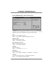
... Set the Smart Monitoring, Analysis, and Reporting T echnology. Change Option F1 General Help F10 Save and Exit ESC Exit vxx.xx (C)Copyright 1985-200x, American Megatrends, Inc. Options: Auto (Default) / 0 / 1 / 2 / 3 / 4 DMA Mode Select the DMA mode. Options: Auto (Default) / Disabled PIO Mode Select the PIO mode. TA790GXE 128M BIOS Manual Primary IDE Master/Slav e ; Options: Auto (Default) / Disabled Block (Multi-Sector Transfer) Enable or disable multi-sector trans fer. SATA 1/2/3/4/5/6 Dev ice Main BIOS SETUP UTILITY Primary IDE Master Device : Type [Auto...
... Set the Smart Monitoring, Analysis, and Reporting T echnology. Change Option F1 General Help F10 Save and Exit ESC Exit vxx.xx (C)Copyright 1985-200x, American Megatrends, Inc. Options: Auto (Default) / 0 / 1 / 2 / 3 / 4 DMA Mode Select the DMA mode. Options: Auto (Default) / Disabled PIO Mode Select the PIO mode. TA790GXE 128M BIOS Manual Primary IDE Master/Slav e ; Options: Auto (Default) / Disabled Block (Multi-Sector Transfer) Enable or disable multi-sector trans fer. SATA 1/2/3/4/5/6 Dev ice Main BIOS SETUP UTILITY Primary IDE Master Device : Type [Auto...
Bios Setup
Page 10
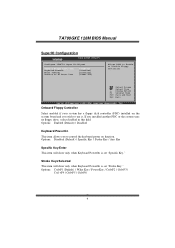
... set "Specific Key." Onboard Floppy Controller Select enabled if your system has a floppy disk controller (FDC) installed on function. If you wish to use it. Options: Disabled (Default) / Specific Key / Stroke Key / Any Key Specific Key Enter T his item will show only when Keyboard PowerOn is set "Stroke Key." TA790GXE 128M BIOS Manual SuperIO Configuration Advanced BIOS S ETUP UTILITY Confi gure ITE8718 Super IO Chi pset Onboa rd Floppy Con troller Keybo ard PowerOn Mouse PowerOn Resto re on AC Powe r Loss [ Enabled] [ Disabled] [ Disabled] [ Power...
... set "Specific Key." Onboard Floppy Controller Select enabled if your system has a floppy disk controller (FDC) installed on function. If you wish to use it. Options: Disabled (Default) / Specific Key / Stroke Key / Any Key Specific Key Enter T his item will show only when Keyboard PowerOn is set "Stroke Key." TA790GXE 128M BIOS Manual SuperIO Configuration Advanced BIOS S ETUP UTILITY Confi gure ITE8718 Super IO Chi pset Onboa rd Floppy Con troller Keybo ard PowerOn Mouse PowerOn Resto re on AC Powe r Loss [ Enabled] [ Disabled] [ Disabled] [ Power...
Bios Setup
Page 13
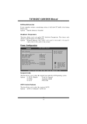
...℃/194℉ Power Configuration Advanced BIOS S ETUP UTILITY ACPI Settings Suspe nd mode ACPI Version Featu res ACPI APIC support AMI O EMB table Headl ess mode [ S1 (POS)] [ ACPI v1.0] [ Enabled] [ Enabled] [ Disabled] RTC R esume [ Disabled] RTC A larm Date(Day s) RTC A larm T ime USB W akeup From S3 /S4 [ Disabled] Power On by PCIE/O nboard LAN [ Disabled] Wake Up by PCI [ Disabled] Sele ct the ACPI stat e used for Syst em Suspend. Options: ACPI v1.0 (Default) / ACPI v2.0 12 TA790GXE 128M BIOS Manual H/W Health Function...
...℃/194℉ Power Configuration Advanced BIOS S ETUP UTILITY ACPI Settings Suspe nd mode ACPI Version Featu res ACPI APIC support AMI O EMB table Headl ess mode [ S1 (POS)] [ ACPI v1.0] [ Enabled] [ Enabled] [ Disabled] RTC R esume [ Disabled] RTC A larm Date(Day s) RTC A larm T ime USB W akeup From S3 /S4 [ Disabled] Power On by PCIE/O nboard LAN [ Disabled] Wake Up by PCI [ Disabled] Sele ct the ACPI stat e used for Syst em Suspend. Options: ACPI v1.0 (Default) / ACPI v2.0 12 TA790GXE 128M BIOS Manual H/W Health Function...
Bios Setup
Page 15
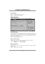
... BIOS S ETUP UTILITY USB C onfiguration Modul e Version - 2 .24.3-13.4 USB D evices Enable d: Legac y USB Support USB 2 .0 Controller Mode BIOS EHCI Hand-Off [ Enabled] [ HiSpeed] [ Enabled] > USB Mass Storage Device Conf iguration Enab les support for operating systems without an EHCI hand-o ff feature. TA790GXE 128M BIOS Manual Wake Up by PCI Enable / Disable PCI to select the operation mode of the USB 2.0 controller. T his is a useful feature when using USB device information. Microso ft DOS or Windows NT). AUTO opti on disables lega cy support i f no U SB devices...
... BIOS S ETUP UTILITY USB C onfiguration Modul e Version - 2 .24.3-13.4 USB D evices Enable d: Legac y USB Support USB 2 .0 Controller Mode BIOS EHCI Hand-Off [ Enabled] [ HiSpeed] [ Enabled] > USB Mass Storage Device Conf iguration Enab les support for operating systems without an EHCI hand-o ff feature. TA790GXE 128M BIOS Manual Wake Up by PCI Enable / Disable PCI to select the operation mode of the USB 2.0 controller. T his is a useful feature when using USB device information. Microso ft DOS or Windows NT). AUTO opti on disables lega cy support i f no U SB devices...
Bios Setup
Page 20
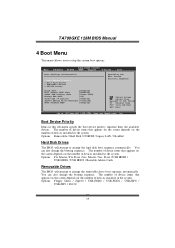
..., Amer ican Megatre nds, Inc. Main BIOS S ETUP UTILITY Advanced PCIPnP Boot Chips et T-Series Exit Boot Settings Conf iguration > Boo t Device Prio rity > Har d Disk Drives > Rem ovable Drives > CD/ DVD Drives Quick Boot [ Enabled] Full Screen LOGO S how [ Enabled] AddOn ROM Display Mode [ Force BIOS] Bootu p Num-Lock [ ON] Inter rupt 19 Captu re [ Enabled] Ignor e Memory Erro r Messages [ Disabled] BOOT SUCCESS BEEP [ Enabled] Spec ifies the Boot Device Prio rity sequenc e. Options: Floppy Disks / Zip100 / USB-FDD0 / USB-FDD1 / USB-ZIP0 / USB-ZIP1 / LS120 19
..., Amer ican Megatre nds, Inc. Main BIOS S ETUP UTILITY Advanced PCIPnP Boot Chips et T-Series Exit Boot Settings Conf iguration > Boo t Device Prio rity > Har d Disk Drives > Rem ovable Drives > CD/ DVD Drives Quick Boot [ Enabled] Full Screen LOGO S how [ Enabled] AddOn ROM Display Mode [ Force BIOS] Bootu p Num-Lock [ ON] Inter rupt 19 Captu re [ Enabled] Ignor e Memory Erro r Messages [ Disabled] BOOT SUCCESS BEEP [ Enabled] Spec ifies the Boot Device Prio rity sequenc e. Options: Floppy Disks / Zip100 / USB-FDD0 / USB-FDD1 / USB-ZIP0 / USB-ZIP1 / LS120 19
Bios Setup
Page 22
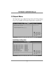
TA790GXE 128M BIOS Manual 5 Chipset Menu T his chipset manage bus speeds and access to Sub Scr een F1 G eneral Help F1 0 S ave and Exit ES C E xit vxx.xx (C)C opyright 198 5-200x, Amer ican Megatre nds, Inc. 21 It also coordinates communications with the PCI bus. Main BIOS S ETUP UTILITY Advanced PCIPnP Boot Chips et T-Series Exit Advan ced Chipset S ettings > Sou thBridge Conf iguration > AMD 790GX Config uration > OnB oard Peripher...
TA790GXE 128M BIOS Manual 5 Chipset Menu T his chipset manage bus speeds and access to Sub Scr een F1 G eneral Help F1 0 S ave and Exit ES C E xit vxx.xx (C)C opyright 198 5-200x, Amer ican Megatre nds, Inc. 21 It also coordinates communications with the PCI bus. Main BIOS S ETUP UTILITY Advanced PCIPnP Boot Chips et T-Series Exit Advan ced Chipset S ettings > Sou thBridge Conf iguration > AMD 790GX Config uration > OnB oard Peripher...
Bios Setup
Page 26
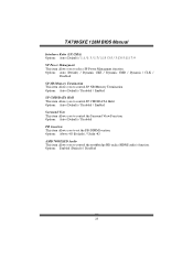
... NB/Memory Termination T his item allows you to select SP Power Managment fun ction. Options: Auto (Default) / Disabled FB Location T his item allows you to control SP CMD/DAT A Hold. Options: Enabled (Default) / Disabled 25 Options: Auto (Default) / Disabled / Enabled SP CMD/DATA Hold T his item allows you to set the FB-DIMM location. Options: Above 4G (Default) / Under 4G AMD 790GX HD Audio T his item allows you to control the Surround View Function. Options: Auto (Default) / Disabled / Enabled...
... NB/Memory Termination T his item allows you to select SP Power Managment fun ction. Options: Auto (Default) / Disabled FB Location T his item allows you to control SP CMD/DAT A Hold. Options: Enabled (Default) / Disabled 25 Options: Auto (Default) / Disabled / Enabled SP CMD/DATA Hold T his item allows you to set the FB-DIMM location. Options: Above 4G (Default) / Under 4G AMD 790GX HD Audio T his item allows you to control the Surround View Function. Options: Auto (Default) / Disabled / Enabled...
Bios Setup
Page 30
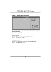
..., Amer ican Megatre nds, Inc. TA790GXE 128M BIOS Manual OnBoard Peripherals Configuration BIOS S ETUP UTILITY Chips et MAC I D Information Realt ek PCIE NIC Real tek Option RO M [ Enable] [ Disabled] Enab le/Disable Onbo ard RTL8111C PCIE Network Cont roller S elect Screen S elect Item +- Options: Disabled (Default) / Enabled 29 Options: Enable (Default) / Disable Realtek Option ROM T his item allows you to enable or disable the Onboard LAN Boot ROM. MAC ID Information T his option allows you to control the onboard LAN controller. Realtek PCIE NIC T his area shows the...
..., Amer ican Megatre nds, Inc. TA790GXE 128M BIOS Manual OnBoard Peripherals Configuration BIOS S ETUP UTILITY Chips et MAC I D Information Realt ek PCIE NIC Real tek Option RO M [ Enable] [ Disabled] Enab le/Disable Onbo ard RTL8111C PCIE Network Cont roller S elect Screen S elect Item +- Options: Disabled (Default) / Enabled 29 Options: Enable (Default) / Disable Realtek Option ROM T his item allows you to enable or disable the Onboard LAN Boot ROM. MAC ID Information T his option allows you to control the onboard LAN controller. Realtek PCIE NIC T his area shows the...
Bios Setup
Page 45
... Boot Chipset T-Series Exit Exit Options Save Changes a nd Exit Discard Change s and Exit Discard Change s Load Optimal D efaults CMOS Backup Fu nction CMOS Backup Func CMOS Data Reload CMOS Data Save Security Setti ngs > Security S elect Screen S elect Item EnterG o to provide/revise supervisor and user password. BIOS SETU P U TILITY Exit Security Setti ngs Supervisor Pas sword :Not Installe d User Password :Not Installe d Change Supervi sor Password User Access Le vel Change User Pa ssword Clear User...
... Boot Chipset T-Series Exit Exit Options Save Changes a nd Exit Discard Change s and Exit Discard Change s Load Optimal D efaults CMOS Backup Fu nction CMOS Backup Func CMOS Data Reload CMOS Data Save Security Setti ngs > Security S elect Screen S elect Item EnterG o to provide/revise supervisor and user password. BIOS SETU P U TILITY Exit Security Setti ngs Supervisor Pas sword :Not Installe d User Password :Not Installe d Change Supervi sor Password User Access Le vel Change User Pa ssword Clear User...


