
M6VLQ user's manual
Page 3
... 1-2 1.1 Features 1-2 1.1.1 Hardware...1-2 1.1.2 Software...1-7 1.1.3 Attachments...1-7 1.2 Motherboard Installation 1-8 1.2.1 System Block Diagram 1-8 1.2.2 Layout of Motherboard 1-9 1.2.3 Quick Reference 1-10 1.3 CPU Installation 1-11 1.3.1 CPU Installation Procedure: Socket 370 1-11 1.3.2 CPU Fan Header: JCFAN1 1-12 1.3.3 System Fan Header: JSFAN1 1-12 1.4 RAM Module Installation 1-...
... 1-2 1.1 Features 1-2 1.1.1 Hardware...1-2 1.1.2 Software...1-7 1.1.3 Attachments...1-7 1.2 Motherboard Installation 1-8 1.2.1 System Block Diagram 1-8 1.2.2 Layout of Motherboard 1-9 1.2.3 Quick Reference 1-10 1.3 CPU Installation 1-11 1.3.1 CPU Installation Procedure: Socket 370 1-11 1.3.2 CPU Fan Header: JCFAN1 1-12 1.3.3 System Fan Header: JSFAN1 1-12 1.4 RAM Module Installation 1-...
M6VLQ user's manual
Page 6
M6VLQ Highlights: 8 Contains on board I/O facilities, which include one serial port, a parallel port, a monitor port, a PS/2 mouse port, a PS/2 keyboard port, audio ports, USB ports and a game port. 8 Contains on board IDE facilities for full compliance and compatibility with the ultimate solution in data processing. Chapter 1 Motherboard... Congratulations on board LAN. 8 Supports the Socket 370. 1-1 In the tradition of your new system! This motherboard is designed to take advantage of the latest industry technology to reliability and performance and strives for IDE devices such...
M6VLQ Highlights: 8 Contains on board I/O facilities, which include one serial port, a parallel port, a monitor port, a PS/2 mouse port, a PS/2 keyboard port, audio ports, USB ports and a game port. 8 Contains on board IDE facilities for full compliance and compatibility with the ultimate solution in data processing. Chapter 1 Motherboard... Congratulations on board LAN. 8 Supports the Socket 370. 1-1 In the tradition of your new system! This motherboard is designed to take advantage of the latest industry technology to reliability and performance and strives for IDE devices such...
M6VLQ user's manual
Page 7
... Bus frequency. 1-2 Supports up to 1.2 GHz CPU core speeds. Micro-Processor (FC-PGA & FC-PGA2) and VIA C3 Samuel 2 for high-end workstations and servers. Motherboard Description 1.1 Features 1.1.1 Hardware CPU − − Supports the CeleronTM processor (FC-PGA & FC-PGA2) and the Pentium® !!! The 33 MHz 32 bit PCI 2.2 compliant...
... Bus frequency. 1-2 Supports up to 1.2 GHz CPU core speeds. Micro-Processor (FC-PGA & FC-PGA2) and VIA C3 Samuel 2 for high-end workstations and servers. Motherboard Description 1.1 Features 1.1.1 Hardware CPU − − Supports the CeleronTM processor (FC-PGA & FC-PGA2) and the Pentium® !!! The 33 MHz 32 bit PCI 2.2 compliant...
M6VLQ user's manual
Page 8
Chapter 1 Motherboard Description Internal Accelerated Graphics Port (AGP) Controller − AGP v1.0 compliant. − Pipelined split-transaction long-burst transfers up to 533 MB/sec. − Eight ...
Chapter 1 Motherboard Description Internal Accelerated Graphics Port (AGP) Controller − AGP v1.0 compliant. − Pipelined split-transaction long-burst transfers up to 533 MB/sec. − Eight ...
M6VLQ user's manual
Page 9
... Engine − 32-bit IEEE floating point input data. − Slope and vertex calculations. − Back facing triangle culling. − 1/16 sub-pixel positioning. Chapter 1 Motherboard Description High Performance rCADE3D™ Accelerator − 32 entry command queue,32 entry data queue. − 4Kbyte texture cache with multiple Level-Of-Detail (LOD...
... Engine − 32-bit IEEE floating point input data. − Slope and vertex calculations. − Back facing triangle culling. − 1/16 sub-pixel positioning. Chapter 1 Motherboard Description High Performance rCADE3D™ Accelerator − 32 entry command queue,32 entry data queue. − 4Kbyte texture cache with multiple Level-Of-Detail (LOD...
M6VLQ user's manual
Page 10
... de-interlace filtering for 16:9 Sequence. Freeze,Fast-Forward, Slow Motion, Reverse. Supports full DVD 1.0,VCD 2.0 and CD-Karaoke. Tamper-proof software CSS implementation. Chapter 1 Motherboard Description DVD − − − − − Hardware-Assisted MPEG-2 Architecture for DVD with 16 byte FIFO. − UART data rates up to MCI. Pan...
... de-interlace filtering for 16:9 Sequence. Freeze,Fast-Forward, Slow Motion, Reverse. Supports full DVD 1.0,VCD 2.0 and CD-Karaoke. Tamper-proof software CSS implementation. Chapter 1 Motherboard Description DVD − − − − − Hardware-Assisted MPEG-2 Architecture for DVD with 16 byte FIFO. − UART data rates up to MCI. Pan...
M6VLQ user's manual
Page 11
... and Configuration and Power Interface) and legacy (APM) power management. − ACPI v1.0 Compliant. − APM v1.2 Compliant. − S3 (suspend to RAM) support. Chapter 1 Motherboard Description − Hardware SoundBlaster Pro for Windows DOS box and real-mode Dos legacy compatibility. − Plug and play with 4 IRQ, 4 DMA, and 4 I/O space options...
... and Configuration and Power Interface) and legacy (APM) power management. − ACPI v1.0 Compliant. − APM v1.2 Compliant. − S3 (suspend to RAM) support. Chapter 1 Motherboard Description − Hardware SoundBlaster Pro for Windows DOS box and real-mode Dos legacy compatibility. − Plug and play with 4 IRQ, 4 DMA, and 4 I/O space options...
M6VLQ user's manual
Page 12
Operating Systems − Offers the highest performance for MS-DOS, Windows NT, Windows 2000, Windows 95/ 98, Windows ME, Windows XP, Novell, LINUX (Red hat 7.0), SCO UNIT. 1.1.3 Attachments − HDD Cable. − FDD Cable. − USB2 Cable (Optional). − Rear I/O Panel for Micro ATX Case (Optional). − CD for sound, VGA, IDE drivers utilities. 1-7 Chapter 1 Motherboard Description 1.1.2 Software BIOS − − Phoenix legal & user-friendly BIOS. Supports PnP functions.
Operating Systems − Offers the highest performance for MS-DOS, Windows NT, Windows 2000, Windows 95/ 98, Windows ME, Windows XP, Novell, LINUX (Red hat 7.0), SCO UNIT. 1.1.3 Attachments − HDD Cable. − FDD Cable. − USB2 Cable (Optional). − Rear I/O Panel for Micro ATX Case (Optional). − CD for sound, VGA, IDE drivers utilities. 1-7 Chapter 1 Motherboard Description 1.1.2 Software BIOS − − Phoenix legal & user-friendly BIOS. Supports PnP functions.
M6VLQ user's manual
Page 13
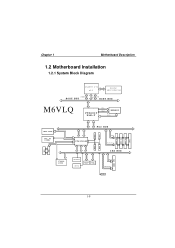
CONN. Chapter 1 Motherboard Description 1.2 Motherboard Installation 1.2.1 System Block Diagram SOCKET 370 CPU CLOCK W93194BR-39B CONTROL HOST BUS ADD DATA HOST BUS M6VLQ VT8601T PLE-T CNTL ADDR MEMORY D ATA AMR SLOT AC' 97 CODEC FLASH BIOS PCI BUS USB USB VT82C686B USB USB CNTL A D D R / D ATA ISA BUS IAS CONN KEYBOARD MOUSE FLOPPY LPT. CONN. CNTL A D D R / D ATA SER. CONN. LAN PCI CONN PCI CONN PCI CONN IDE IDE 1-8
CONN. Chapter 1 Motherboard Description 1.2 Motherboard Installation 1.2.1 System Block Diagram SOCKET 370 CPU CLOCK W93194BR-39B CONTROL HOST BUS ADD DATA HOST BUS M6VLQ VT8601T PLE-T CNTL ADDR MEMORY D ATA AMR SLOT AC' 97 CODEC FLASH BIOS PCI BUS USB USB VT82C686B USB USB CNTL A D D R / D ATA ISA BUS IAS CONN KEYBOARD MOUSE FLOPPY LPT. CONN. CNTL A D D R / D ATA SER. CONN. LAN PCI CONN PCI CONN PCI CONN IDE IDE 1-8
M6VLQ user's manual
Page 14
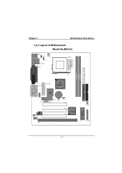
SECONDARY IDE CONN. IDE1 IDE2 JSFAN1 BIOS ROM1 21 JPANEL1 1-9 JVGA1 JSPKR1 SP-OUT JGAME1 GAME Port JLIN1 LINE-IN JMIC1 MIC-IN JAUDIO1 JWOL1 JATXPWR1 VT 8601T LAN 8100 AMR1 JWOM1 BAT1 JCMOS1 PCI1 JCDIN2 JCDIN1 JTAD1 JUSBV2 JUSB2 ISA1 PCI2 PCI3 VT 82C686B PRIMARY IDE CONN. Chapter 1 Motherboard Description 1.2.2 Layout of Motherboard Model No.M6VLQ JKBMS1 JKBV1 JC FA N1 JUSBV1 JUSBLAN1 JCOM1 JPRNT1 FDD1 CPU1 DIMM1 DIMM2 FLOPPY DISK CONN.
SECONDARY IDE CONN. IDE1 IDE2 JSFAN1 BIOS ROM1 21 JPANEL1 1-9 JVGA1 JSPKR1 SP-OUT JGAME1 GAME Port JLIN1 LINE-IN JMIC1 MIC-IN JAUDIO1 JWOL1 JATXPWR1 VT 8601T LAN 8100 AMR1 JWOM1 BAT1 JCMOS1 PCI1 JCDIN2 JCDIN1 JTAD1 JUSBV2 JUSB2 ISA1 PCI2 PCI3 VT 82C686B PRIMARY IDE CONN. Chapter 1 Motherboard Description 1.2.2 Layout of Motherboard Model No.M6VLQ JKBMS1 JKBV1 JC FA N1 JUSBV1 JUSBLAN1 JCOM1 JPRNT1 FDD1 CPU1 DIMM1 DIMM2 FLOPPY DISK CONN.
M6VLQ user's manual
Page 15
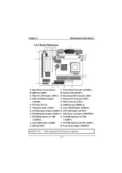
... for USB U. 5V/5VSB Selection for KB (*JKBV1) K. Front Audio Header (JAUDIO1) NOTE: The " * "mark represent the function is optional. 1-10 FDD Connector (FDD1) E. Chapter 1 Motherboard Description 1.2.3 Quick Reference I /O Connectors L. System FAN (JSFAN1) C. DIMM Sockets (DIMM1-2) F. CPU FAN Header (JCFAN1) H. Front USB Header (JUSB2) V. 5V/5VSB Selection for USB (*JUSBV2) (*JUSBV1...
... for USB U. 5V/5VSB Selection for KB (*JKBV1) K. Front Audio Header (JAUDIO1) NOTE: The " * "mark represent the function is optional. 1-10 FDD Connector (FDD1) E. Chapter 1 Motherboard Description 1.2.3 Quick Reference I /O Connectors L. System FAN (JSFAN1) C. DIMM Sockets (DIMM1-2) F. CPU FAN Header (JCFAN1) H. Front USB Header (JUSB2) V. 5V/5VSB Selection for USB (*JUSBV2) (*JUSBV1...
M6VLQ user's manual
Page 16
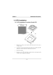
Locate Pin A in the CPU. Press the lever down. 4. Chapter 1 Motherboard Description 1.3 CPU Installation 1.3.1 CPU Installation Procedure: Socket 370 Socket 370 1. Match Pin A with the white dot/cut edge in the socket and look for the white dot or cut edge then insert the CPU. 3. Pull the lever sideways away from the socket then raise the lever up to complete the installation. 1-11 Put the fan on the CPU and buckle it and put the fan's power-port into the JCFAN1, then to a 90-degree angle. 2.
Locate Pin A in the CPU. Press the lever down. 4. Chapter 1 Motherboard Description 1.3 CPU Installation 1.3.1 CPU Installation Procedure: Socket 370 Socket 370 1. Match Pin A with the white dot/cut edge in the socket and look for the white dot or cut edge then insert the CPU. 3. Pull the lever sideways away from the socket then raise the lever up to complete the installation. 1-11 Put the fan on the CPU and buckle it and put the fan's power-port into the JCFAN1, then to a 90-degree angle. 2.
M6VLQ user's manual
Page 17
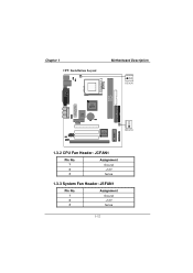
Chapter 1 CPU Installation Layout Motherboard Description 1 JCFAN1 DIMM1 DIMM2 VT 8601T LAN 8100 VT 82C686B 1 JSFAN1 BIOS 1.3.2 CPU Fan Header: JCFAN1 Pin No. 1 2 3 Assignment Ground +12V Sense 1.3.3 System Fan Header: JSFAN1 Pin No. 1 2 3 Assignment Ground +12V Sense 1-12
Chapter 1 CPU Installation Layout Motherboard Description 1 JCFAN1 DIMM1 DIMM2 VT 8601T LAN 8100 VT 82C686B 1 JSFAN1 BIOS 1.3.2 CPU Fan Header: JCFAN1 Pin No. 1 2 3 Assignment Ground +12V Sense 1.3.3 System Fan Header: JSFAN1 Pin No. 1 2 3 Assignment Ground +12V Sense 1-12
M6VLQ user's manual
Page 18
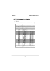
Chapter 1 Motherboard Description 1.4 RAM Module Installation 1.4.1 DIMM DRAM Access Time: 3.3V Unbuffered SDRAM PC100/133 Type required. DRAM Type: 64MB/ 128MB/ 256MB/512MB DIMM Module (168 pin) ...
Chapter 1 Motherboard Description 1.4 RAM Module Installation 1.4.1 DIMM DRAM Access Time: 3.3V Unbuffered SDRAM PC100/133 Type required. DRAM Type: 64MB/ 128MB/ 256MB/512MB DIMM Module (168 pin) ...
M6VLQ user's manual
Page 19
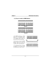
Insert the DIMM memory modules into the socket at a 90-degree angle then push down vertically so that it will fit into the slot in place. 1-14 The Mounting Holes and plastic tabs should fit over the edge and hold the DIMM memory modules in one direction. 2. Chapter 1 Motherboard Description 1.4.2 How to install a DIMM Module 1. The DIMM socket has a " Plastic Safety Tab" and the DIMM memory module has an asymmetrical notch", so the DIMM memory module can only fit into place. 3. Push the tabs out.
Insert the DIMM memory modules into the socket at a 90-degree angle then push down vertically so that it will fit into the slot in place. 1-14 The Mounting Holes and plastic tabs should fit over the edge and hold the DIMM memory modules in one direction. 2. Chapter 1 Motherboard Description 1.4.2 How to install a DIMM Module 1. The DIMM socket has a " Plastic Safety Tab" and the DIMM memory module has an asymmetrical notch", so the DIMM memory module can only fit into place. 3. Push the tabs out.
M6VLQ user's manual
Page 20
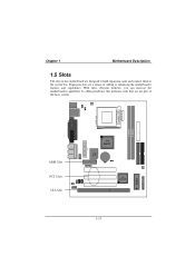
DIMM1 DIMM2 BIOS AMR Slot PCI Slots ISA Slot VT 8601T LAN 8100 VT 82C686B 1-15 Expansion slots are not part of adding or enhancing the motherboard's features and capabilities. With these efficient facilities, you can increase the motherboard's capabilities by adding hardware that performs tasks that are a means of the basic system. Chapter 1 Motherboard Description 1.5 Slots The slots in this motherboard are designed to hold expansion cards and connect them to the system bus.
DIMM1 DIMM2 BIOS AMR Slot PCI Slots ISA Slot VT 8601T LAN 8100 VT 82C686B 1-15 Expansion slots are not part of adding or enhancing the motherboard's features and capabilities. With these efficient facilities, you can increase the motherboard's capabilities by adding hardware that performs tasks that are a means of the basic system. Chapter 1 Motherboard Description 1.5 Slots The slots in this motherboard are designed to hold expansion cards and connect them to the system bus.
M6VLQ user's manual
Page 21
...and that defines a hardware scalable riser card interface, which supports audio and modem only. 1.5.2 PCI (Peripheral Component Interconnect) Slots This motherboard is equipped with one standard ISA slot. ISA stands for PC XT/AT machines. This PCI slot is designated as a bus standard...90's for Industry Standard Architecture and was designed as 32 bit. 1.5.3 ISA (Industry Standard Architecture) Slot The motherboard is equipped with 3 standard PCI slots. This motherboard retains backward compatibility with has, for expansion cards, with this order and slower bus architecture. 1-16 PCI ...
...and that defines a hardware scalable riser card interface, which supports audio and modem only. 1.5.2 PCI (Peripheral Component Interconnect) Slots This motherboard is equipped with one standard ISA slot. ISA stands for PC XT/AT machines. This PCI slot is designated as a bus standard...90's for Industry Standard Architecture and was designed as 32 bit. 1.5.3 ISA (Industry Standard Architecture) Slot The motherboard is equipped with 3 standard PCI slots. This motherboard retains backward compatibility with has, for expansion cards, with this order and slower bus architecture. 1-16 PCI ...
M6VLQ user's manual
Page 22
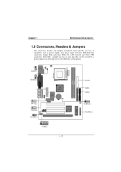
Chapter 1 Motherboard Description 1.6 Connectors, Headers & Jumpers The connectors, headers and jumpers introduced below provide you to select different system options. 1 JKBV1 1 JUSBV1 1 JWOL1 1 JWOM1 1 JUSBV2 VT 8601T LAN 8100 VT 82C686B 1 JUSB2 DIMM1 DIMM2 BIOS FDD1 IDE1 IDE2 1 JCMOS1 JPANEL1 1-17 Noticeably, a jumper has two or more pins that can be covered by a plastic jumper cap, allowing you lots of capabilities such as power supply, front panel signal revelation, IDE hard disk connection, floppy disk connection, Wake On LAN function and Front USB connection.
Chapter 1 Motherboard Description 1.6 Connectors, Headers & Jumpers The connectors, headers and jumpers introduced below provide you to select different system options. 1 JKBV1 1 JUSBV1 1 JWOL1 1 JWOM1 1 JUSBV2 VT 8601T LAN 8100 VT 82C686B 1 JUSB2 DIMM1 DIMM2 BIOS FDD1 IDE1 IDE2 1 JCMOS1 JPANEL1 1-17 Noticeably, a jumper has two or more pins that can be covered by a plastic jumper cap, allowing you lots of capabilities such as power supply, front panel signal revelation, IDE hard disk connection, floppy disk connection, Wake On LAN function and Front USB connection.
M6VLQ user's manual
Page 23
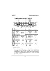
The speaker is not connected to the motherboard at the front panel connector. The speaker (onboard or offboard) provides error beep code information during the Power On Self-Test when the computer cannot ...use the video interface. An offboard speaker can be connected to the audio subsystem and does not receive output from the audio subsystem. 1-18 Chapter 1 Motherboard Description 1.6.1 Front Panel Connector: JPANEL1 K SLP NA PLED PWR E (+) (+) (-) Y IrDA 2 24 1 23 (+) (-) SPEK HDLED REST NA IrDA Pin Assignment No. 1 Speaker 3 NC 5 Ground 7 +5V 9 HDD...
The speaker is not connected to the motherboard at the front panel connector. The speaker (onboard or offboard) provides error beep code information during the Power On Self-Test when the computer cannot ...use the video interface. An offboard speaker can be connected to the audio subsystem and does not receive output from the audio subsystem. 1-18 Chapter 1 Motherboard Description 1.6.1 Front Panel Connector: JPANEL1 K SLP NA PLED PWR E (+) (+) (-) Y IrDA 2 24 1 23 (+) (-) SPEK HDLED REST NA IrDA Pin Assignment No. 1 Speaker 3 NC 5 Ground 7 +5V 9 HDD...
M6VLQ user's manual
Page 24
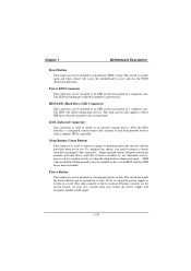
... and hard drives until the system is invoked by any keyboard activity, mouse activity, modem activity or when the sleep button is powered on. Chapter 1 Motherboard Description Reset Button This connector can be attached to an LED on the front panel of a computer case. The LED will illuminate while the computer... the monitor and the hard disk when not in the system BIOS and the APM driver must pass before the power supply will cause the motherboard to the system board.
... and hard drives until the system is invoked by any keyboard activity, mouse activity, modem activity or when the sleep button is powered on. Chapter 1 Motherboard Description Reset Button This connector can be attached to an LED on the front panel of a computer case. The LED will illuminate while the computer... the monitor and the hard disk when not in the system BIOS and the APM driver must pass before the power supply will cause the motherboard to the system board.

