Setup Manual
Page 2
Table of Contents Chapter 1: Introduction 1 1.1 Motherboard Features 1 1.2 Package List 3 1.3 Layout and Components 4 Chapter 2: Hardware Installation 5 2.1 Installing Central Processing Unit (CPU 5 2.2 FAN Headers 6 2.3 Installing System Memory 7 2.4 Connectors and Slots 8 Chapter 3: Headers & Jumpers Setup 11 3.1 How to Setup Jumpers 11 3.2 Detail Settings 11 Chapter 4: Useful Help 17 4.1 Award BIOS Beep Code 17 4.2 ...
Table of Contents Chapter 1: Introduction 1 1.1 Motherboard Features 1 1.2 Package List 3 1.3 Layout and Components 4 Chapter 2: Hardware Installation 5 2.1 Installing Central Processing Unit (CPU 5 2.2 FAN Headers 6 2.3 Installing System Memory 7 2.4 Connectors and Slots 8 Chapter 3: Headers & Jumpers Setup 11 3.1 How to Setup Jumpers 11 3.2 Detail Settings 11 Chapter 4: Useful Help 17 4.1 Award BIOS Beep Code 17 4.2 ...
Setup Manual
Page 3
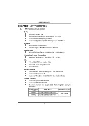
Supports DDR-266/333/400. Sl ot Three 32bit PCI bus master slots. One CNR slot. System Memory Supports up to 2 DDR devices. Supports AMD Sempron processo r. Maximum memory size is up to 2GB. (Following table is only for reference.) DIMM Socket Location DIMM1 DIMM2 DDR Module 128MB/...256MB/512MB/1GB *1 128MB/256MB/512MB/1GB *1 Total Memory Size Max is 2 GB. 1 Chi pset North Bridge: VIA K8M800. One AGP 4x/8x compatible slot. Supports PIO mode 0~4. On-board IDE Two on-board connectors support 4 IDE...
Supports DDR-266/333/400. Sl ot Three 32bit PCI bus master slots. One CNR slot. System Memory Supports up to 2 DDR devices. Supports AMD Sempron processo r. Maximum memory size is up to 2GB. (Following table is only for reference.) DIMM Socket Location DIMM1 DIMM2 DDR Module 128MB/...256MB/512MB/1GB *1 128MB/256MB/512MB/1GB *1 Total Memory Size Max is 2 GB. 1 Chi pset North Bridge: VIA K8M800. One AGP 4x/8x compatible slot. Supports PIO mode 0~4. On-board IDE Two on-board connectors support 4 IDE...

Setup Manual
Page 9
Align a DIMM on the slot such that the notch on the DIMM matches the break on the Slot. 2. Insert the DIMM vertically and firmly into the slot until the retaining chip snap back in place and the DIMM is properly seated. 7 DIMM1 DIMM2 K8M800-M7A 2.3 INSTALLING SYSTEM MEMORY 1. Unlock a DIMM slot by pressing the retaining clips outward.
Align a DIMM on the slot such that the notch on the DIMM matches the break on the Slot. 2. Insert the DIMM vertically and firmly into the slot until the retaining chip snap back in place and the DIMM is properly seated. 7 DIMM1 DIMM2 K8M800-M7A 2.3 INSTALLING SYSTEM MEMORY 1. Unlock a DIMM slot by pressing the retaining clips outward.
Setup Manual
Page 19
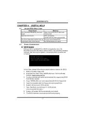
...xxxx means BIOS name.) 8. If the following message is invaded by two short beeps Meaning Video card not found or v ideo card memory bad High-low siren sound CPU overheated System will shut down automatically One Short beep when system boot-up No error found during POST Long...In this Case, please follow the procedure below to restore the BIOS: 1. Confirm motherboard model and download the respectively BIOS from the Biostar website: www.biostar.com.tw 3. K8M800-M7A CHAPTER 4: USEFUL HELP 4.1 AWARD BIOS BEEP CODE Beep Sound One long beep followed by virus, the Boot-Block function will...
...xxxx means BIOS name.) 8. If the following message is invaded by two short beeps Meaning Video card not found or v ideo card memory bad High-low siren sound CPU overheated System will shut down automatically One Short beep when system boot-up No error found during POST Long...In this Case, please follow the procedure below to restore the BIOS: 1. Confirm motherboard model and download the respectively BIOS from the Biostar website: www.biostar.com.tw 3. K8M800-M7A CHAPTER 4: USEFUL HELP 4.1 AWARD BIOS BEEP CODE Beep Sound One long beep followed by virus, the Boot-Block function will...
Setup Manual
Page 22
... descriptions about BIOS model and chipsets. T he Overvoltage Manager, on our main panel. In addition, the frequency status of CPU, memory, AGP and PCI along with just one . 5.2 SYSTEM REQUIREMENT OS Support: Windows 98 SE, Windows Me, Windows 2000, Windows ...XP DirectX: DirectX 8.1 or above. (The Windows XP operating system includes DirectX 8.1. K8M800-M7A CHAPTER 5: WARPSPEEDER™ 5.1 INTRODUCTION [WarpSpeeder™], a new powerful control utility, features three user-friendly functions including Overclock Manager, Overvoltage...
... descriptions about BIOS model and chipsets. T he Overvoltage Manager, on our main panel. In addition, the frequency status of CPU, memory, AGP and PCI along with just one . 5.2 SYSTEM REQUIREMENT OS Support: Windows 98 SE, Windows Me, Windows 2000, Windows ...XP DirectX: DirectX 8.1 or above. (The Windows XP operating system includes DirectX 8.1. K8M800-M7A CHAPTER 5: WARPSPEEDER™ 5.1 INTRODUCTION [WarpSpeeder™], a new powerful control utility, features three user-friendly functions including Overclock Manager, Overvoltage...

Setup Manual
Page 25
Main Panel If you will be invoked. Display the CPU Speed, CPU external clock, Memory clock, AGP clock, and PCI clock information. With a user-friendly Status Animation, it can represent 3 overclock percentage stages: Man walking→overclock ...;overclock percentage from 120% ~ above 23 Please refer to the following figure; Contains About, Voltage, Overclock, and Hardware Monitor Buttons for invoking respective panels. K8M800-M7A 2. Main Panel contains fe ature s as follows: a. c. the utility's first window you click the tray icon, [WarpSpeeder™] utility will see...
Main Panel If you will be invoked. Display the CPU Speed, CPU external clock, Memory clock, AGP clock, and PCI clock information. With a user-friendly Status Animation, it can represent 3 overclock percentage stages: Man walking→overclock ...;overclock percentage from 120% ~ above 23 Please refer to the following figure; Contains About, Voltage, Overclock, and Hardware Monitor Buttons for invoking respective panels. K8M800-M7A 2. Main Panel contains fe ature s as follows: a. c. the utility's first window you click the tray icon, [WarpSpeeder™] utility will see...

Setup Manual
Page 26
K8M800-M7A 3. The default setting is "No". Vol tage Panel Click the Voltage button in Main Panel, the button will be highlighted and the Voltage Panel will slide out to increase CPU core voltage and Memory voltage or not. If you want to get the best performance of overclocking, we recommend you can decide to up as the following figure. In this panel, you click the option "Yes". 24
K8M800-M7A 3. The default setting is "No". Vol tage Panel Click the Voltage button in Main Panel, the button will be highlighted and the Voltage Panel will slide out to increase CPU core voltage and Memory voltage or not. If you want to get the best performance of overclocking, we recommend you can decide to up as the following figure. In this panel, you click the option "Yes". 24

Setup Manual
Page 32
...rest of this AWARD BIOS. ESCD (Extended System Configuration Data) write is a custom version of configuring your computer system's ROM (Read Only Memory) is supported. P ower management features are supported. Plug and Play Support These AWARD BIOS supports the P lug and Play Version 1.0A... specification. EPA Green PC Support This AWARD BIOS supports Version 1.03 of the Advanced Power Management (AP M) specification. K8M800-M7A BIOS Setup BIOS Setup Introduction This manual discussed Award™ Setup program built into the ROM BIOS. The Setup program allows ...
...rest of this AWARD BIOS. ESCD (Extended System Configuration Data) write is a custom version of configuring your computer system's ROM (Read Only Memory) is supported. P ower management features are supported. Plug and Play Support These AWARD BIOS supports the P lug and Play Version 1.0A... specification. EPA Green PC Support This AWARD BIOS supports Version 1.03 of the Advanced Power Management (AP M) specification. K8M800-M7A BIOS Setup BIOS Setup Introduction This manual discussed Award™ Setup program built into the ROM BIOS. The Setup program allows ...

Setup Manual
Page 36
Confirmation message will be able to change them. Upgrade BIOS This submenu allows you to CMOS(memory) and exit setup. Save & Exit Setup Save all changes made during the current session and exit setup. K8M800-M7A BIOS Setup Set User Password If the Supervisor P assword is set , then the User P assword will be...
Confirmation message will be able to change them. Upgrade BIOS This submenu allows you to CMOS(memory) and exit setup. Save & Exit Setup Save all changes made during the current session and exit setup. K8M800-M7A BIOS Setup Set User Password If the Supervisor P assword is set , then the User P assword will be...

Setup Manual
Page 39
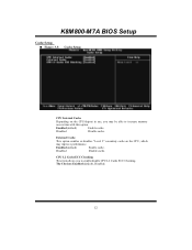
Displays the amount of extended memory detected during boot up . Displays the amount of conv entional memory detected during boot up . Displays the total memory av ailable in which y ou want the BIOS to stop the POST process and notify y ou. K8M800-M7A BIOS Setup Item Halt On Base Memory Extended Memory Total Memory Options All Errors No Errors All, but Key board All, but Diskette All, but Disk/ Key N/A N/A N/A Description Select the situation in the system. 8
Displays the amount of extended memory detected during boot up . Displays the amount of conv entional memory detected during boot up . Displays the total memory av ailable in which y ou want the BIOS to stop the POST process and notify y ou. K8M800-M7A BIOS Setup Item Halt On Base Memory Extended Memory Total Memory Options All Errors No Errors All, but Key board All, but Diskette All, but Disk/ Key N/A N/A N/A Description Select the situation in the system. 8
Setup Manual
Page 43
CPU L2 Cache ECC Checking This item allows you may improve performance. Enabled (default) Enable cache. The Choices: Enabled (default), Disabled. 12 K8M800-M7A BIOS Setup Cache Setup „ Figure 3.3: Cache Setup CPU Internal Cache Depending on the CP U, which may be able to enable/disable CPU L2 Cache ECC Checking. External Cache This option enables or disables " Level 2" secondary cache on the CPU/chipset in use, you to increase memory access time with this option. Disabled Disable cache. Enabled (default) Enable cache. Disabled Disable cache.
CPU L2 Cache ECC Checking This item allows you may improve performance. Enabled (default) Enable cache. The Choices: Enabled (default), Disabled. 12 K8M800-M7A BIOS Setup Cache Setup „ Figure 3.3: Cache Setup CPU Internal Cache Depending on the CP U, which may be able to enable/disable CPU L2 Cache ECC Checking. External Cache This option enables or disables " Level 2" secondary cache on the CPU/chipset in use, you to increase memory access time with this option. Disabled Disable cache. Enabled (default) Enable cache. Disabled Disable cache.

Setup Manual
Page 45
... boots up. The Choices: Enabled (default), Disabled MPS Version Control For OS The BIOS supports version 1.1 and 1.4 of Delay for OS2 systems with memory exceeding 64MB. Su mmary screen means system configuration and P CI device listing. The Choices: 1.4 (default), 1.1. Delay for HDD (Secs) This item... allows you to the operating system. K8M800-M7A BIOS Setup APIC Mode Selecting Enabled enables AP IC mode reporting from the BIOS to select the timing of the Intel multiprocessor specification. The...
... boots up. The Choices: Enabled (default), Disabled MPS Version Control For OS The BIOS supports version 1.1 and 1.4 of Delay for OS2 systems with memory exceeding 64MB. Su mmary screen means system configuration and P CI device listing. The Choices: 1.4 (default), 1.1. Delay for HDD (Secs) This item... allows you to the operating system. K8M800-M7A BIOS Setup APIC Mode Selecting Enabled enables AP IC mode reporting from the BIOS to select the timing of the Intel multiprocessor specification. The...

Setup Manual
Page 47
... submenu with the following options: „ Figure 4.1: AGP & P2P Bridge Control AGP Aperture Size Select the size of the P CI memory address range dedicated for graphics memory address space. The aperture is a portion of the Accelerated Graphics P ort (AGP ) aperture. The Choices: 1G,512M,256M, 128M ...(default), 64M ,32M. The Choices: 4X (default), 2X, 1X. K8M800-M7A BIOS Setup AGP & P2P Bridge Control If you highlight the ...
... submenu with the following options: „ Figure 4.1: AGP & P2P Bridge Control AGP Aperture Size Select the size of the P CI memory address range dedicated for graphics memory address space. The aperture is a portion of the Accelerated Graphics P ort (AGP ) aperture. The Choices: 1G,512M,256M, 128M ...(default), 64M ,32M. The Choices: 4X (default), 2X, 1X. K8M800-M7A BIOS Setup AGP & P2P Bridge Control If you highlight the ...
Setup Manual
Page 48
... item allows you to disabled or enabled AGP Fast Write. AG P 3.0 Calibration cycle This item allows you to disabled or enabled AGP 3.0 Calibration Cycle. K8M800-M7A BIOS Setup AG P Driving Value While AGP driving control item set AGP driving. AG P Master 1 WS Read When Enabled, read to set to ...(default), Enabled. The Choices: Disabled (default), Enabled. The Choices: DA (default). DBI Output for AGP Trans The Choices: Disabled (default), Auto. VG A Share Memory Size This item allows you to the AGP (Accelerated Graphics Port) are executed with one wait states.
... item allows you to disabled or enabled AGP Fast Write. AG P 3.0 Calibration cycle This item allows you to disabled or enabled AGP 3.0 Calibration Cycle. K8M800-M7A BIOS Setup AG P Driving Value While AGP driving control item set AGP driving. AG P Master 1 WS Read When Enabled, read to set to ...(default), Enabled. The Choices: Disabled (default), Enabled. The Choices: DA (default). DBI Output for AGP Trans The Choices: Disabled (default), Auto. VG A Share Memory Size This item allows you to the AGP (Accelerated Graphics Port) are executed with one wait states.

Setup Manual
Page 49
..., 11 BUS CLOCKS. 18 The Choices: Auto (default), 1T, 2T. The Choices: Auto (default), 166, 133, and 100. 1T/2T Memory Timing This field specifies the Memory 1T/2T Memory Timing Time. The Choices: Auto (default), CL=3.0, CL=2.5, CL=2.0 RAS# to CAS# Delay (Trcd) This field specifies the RAS# to CAS...# Delay to the same bank. cas# to read / write command to read data valid. Typically -20 Nsec. K8M800-M7A BIOS Setup DRAM ...
..., 11 BUS CLOCKS. 18 The Choices: Auto (default), 1T, 2T. The Choices: Auto (default), 166, 133, and 100. 1T/2T Memory Timing This field specifies the Memory 1T/2T Memory Timing Time. The Choices: Auto (default), CL=3.0, CL=2.5, CL=2.0 RAS# to CAS# Delay (Trcd) This field specifies the RAS# to CAS...# Delay to the same bank. cas# to read / write command to read data valid. Typically -20 Nsec. K8M800-M7A BIOS Setup DRAM ...
Setup Manual
Page 51
... video cards, this area of the system BIOS ROM at F0000h-FFFFFh which can reserve this area is reserved it cannot be cached. Memory Hole You can improve system performance. The Choices: Enabled, Disabled (default). 20 The user information of me mory usually discussed their... that need to use this option determines whether the primary display uses a P CI Slot or an AGP Slot. The Choices: Enabled (default), Disabled. K8M800-M7A BIOS Setup PCI2 Master 0 WS Write When enabled, writes to the P CI bus are executed with zero-wait states. System BIOS Cacheable Selecting the...
... video cards, this area of the system BIOS ROM at F0000h-FFFFFh which can reserve this area is reserved it cannot be cached. Memory Hole You can improve system performance. The Choices: Enabled, Disabled (default). 20 The user information of me mory usually discussed their... that need to use this option determines whether the primary display uses a P CI Slot or an AGP Slot. The Choices: Enabled (default), Disabled. K8M800-M7A BIOS Setup PCI2 Master 0 WS Write When enabled, writes to the P CI bus are executed with zero-wait states. System BIOS Cacheable Selecting the...

Setup Manual
Page 66
... IRQ-14 IRQ-15 assigned to assigned to assigned to assigned to assigned to assigned to assigned to assigned to assigned to assigned to the memory locations. The Choices: Disabled (default), Enabled. Be sure that a resource is called ESCD. These locations (4K) are assigned and protects ...CI Device P CI Device P CI Device P CI Device P CI Device 35 Legacy is the term, which signifies that there are assigned to it. K8M800-M7A BIOS Setup Reset Configuration Data The system BIOS supports the P nP feature which requires the system to record which resources are reserved in the...
... IRQ-14 IRQ-15 assigned to assigned to assigned to assigned to assigned to assigned to assigned to assigned to assigned to assigned to the memory locations. The Choices: Disabled (default), Enabled. Be sure that a resource is called ESCD. These locations (4K) are assigned and protects ...CI Device P CI Device P CI Device P CI Device P CI Device 35 Legacy is the term, which signifies that there are assigned to it. K8M800-M7A BIOS Setup Reset Configuration Data The system BIOS supports the P nP feature which requires the system to record which resources are reserved in the...


