Setup Manual
Page 2
Table of Contents Chapter 1: Introduction 1 1.1 Before You Start 1 1.2 Package Checklist 1 1.3 Motherboard Features 2 1.4 Rear Panel Connectors 3 1.5 Motherboard Layout 4 Chapter 2: Hardware Installation 5 2.1 Installing Central Processing Unit (CPU 5 2.2 FAN Headers 7 2.3 Installing System Memory 8... Chapter 6: WarpSpeeder 23 6.1 Introductio n 23 6.2 System Requirement 23 6.3 Installation 24 6.4 WarpSpee de r 25 Appendencies: SPEC In Other Language 32 Ge rman 32 France 34 Italian 36 Spanish 38 Po rtuguese 40 Polish 42 Russian 44 Arabic 46 Japanese...
Table of Contents Chapter 1: Introduction 1 1.1 Before You Start 1 1.2 Package Checklist 1 1.3 Motherboard Features 2 1.4 Rear Panel Connectors 3 1.5 Motherboard Layout 4 Chapter 2: Hardware Installation 5 2.1 Installing Central Processing Unit (CPU 5 2.2 FAN Headers 7 2.3 Installing System Memory 8... Chapter 6: WarpSpeeder 23 6.1 Introductio n 23 6.2 System Requirement 23 6.3 Installation 24 6.4 WarpSpee de r 25 Appendencies: SPEC In Other Language 32 Ge rman 32 France 34 Italian 36 Spanish 38 Po rtuguese 40 Polish 42 Russian 44 Arabic 46 Japanese...

Setup Manual
Page 4
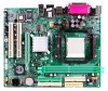
... / 66 / 100 / 133Bus Master supports PIO Mode 0~4, Mode SATA IntegratedSerial ATA Controller Data transfer rates up to 1.5 Gb/s. SATA Version 1.0specificationcompliant. Motherboard Manual 1.3 MOT HERBOARD FEAT URES SPEC CPU Socket AM2 AMDSempron processors Supports Hyper Transport andCool=n=Quiet FSB Chipset Support HyperTransport K8M80 0 VT823 7R+ ITE IT8705 Supports up to 800MHz Bandwidth Environment...
... / 66 / 100 / 133Bus Master supports PIO Mode 0~4, Mode SATA IntegratedSerial ATA Controller Data transfer rates up to 1.5 Gb/s. SATA Version 1.0specificationcompliant. Motherboard Manual 1.3 MOT HERBOARD FEAT URES SPEC CPU Socket AM2 AMDSempron processors Supports Hyper Transport andCool=n=Quiet FSB Chipset Support HyperTransport K8M80 0 VT823 7R+ ITE IT8705 Supports up to 800MHz Bandwidth Environment...

Setup Manual
Page 18
Motherboard Manual JSATA1~JSATA2: Se rial ATA C onne ctors The motherboard has a PCI to connect the PCI bracket SPDIF output header. 13 Pin Assignment 1 +5V 2 SPDIF_OUT 1 3 Ground 16 JSATA1 JSATA2 741 Pin Assignment 1 Ground 2 TX+ 3 TX4 Ground 5 RX6 RX+ 7 Ground JSPDIF_O UT1: Digital Audio out Conne ctors This connector allows user to SATA Controller with 2 channels SATA interface, it satisfies the SATA 1.0 spec and with transfer rate of 1.5Gb/s.
Motherboard Manual JSATA1~JSATA2: Se rial ATA C onne ctors The motherboard has a PCI to connect the PCI bracket SPDIF output header. 13 Pin Assignment 1 +5V 2 SPDIF_OUT 1 3 Ground 16 JSATA1 JSATA2 741 Pin Assignment 1 Ground 2 TX+ 3 TX4 Ground 5 RX6 RX+ 7 Ground JSPDIF_O UT1: Digital Audio out Conne ctors This connector allows user to SATA Controller with 2 channels SATA interface, it satisfies the SATA 1.0 spec and with transfer rate of 1.5Gb/s.

