Bios Setup
Page 3
...Rate Synchronous DRAM) is supported. Quit and not save changes into CMOS Status Page Setup Menu and Option Page Setup Menu - GF7050V-M7 ACPI Support Phoenix-Award ACPI BIOS support Version 1.0b of the Intel PCI (Peripheral Component Interconnect) local bus specification. Supported CPUs ...This PHOENIX-AWARD BIOS supports the Intel CPU. PCI Bus Support This PHOENIX-AWARD BIOS also supports Version 2.3 of Advanced Configuration and Power interface specification (ACPI). Keystroke Up ...
...Rate Synchronous DRAM) is supported. Quit and not save changes into CMOS Status Page Setup Menu and Option Page Setup Menu - GF7050V-M7 ACPI Support Phoenix-Award ACPI BIOS support Version 1.0b of the Intel PCI (Peripheral Component Interconnect) local bus specification. Supported CPUs ...This PHOENIX-AWARD BIOS supports the Intel CPU. PCI Bus Support This PHOENIX-AWARD BIOS also supports Version 2.3 of Advanced Configuration and Power interface specification (ACPI). Keystroke Up ...
Bios Setup
Page 5
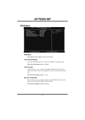
GF7050V-M7 Advanced BIOS Features This submenu allows you to configure advanced features of your system. Changing the voltage and clock improperly may damage the CPU or M/B!) Load Optimized Defaults This selection allows you to configure special chipset features. A confirmation message will be displayed before... allows you to configure certain "Plug and Play" and PCI options. Performance Booster Zone This submenu allows you to change CPU Vcore Voltage and CPU/PCI clock. (However, we suggest you to monitor the hardware of the BIOS. Power Management Setup This submenu allows you...
GF7050V-M7 Advanced BIOS Features This submenu allows you to configure advanced features of your system. Changing the voltage and clock improperly may damage the CPU or M/B!) Load Optimized Defaults This selection allows you to configure special chipset features. A confirmation message will be displayed before... allows you to configure certain "Plug and Play" and PCI options. Performance Booster Zone This submenu allows you to change CPU Vcore Voltage and CPU/PCI clock. (However, we suggest you to monitor the hardware of the BIOS. Power Management Setup This submenu allows you...
Bios Setup
Page 11
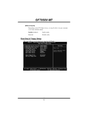
Disab led Disable cache. Boot Seq & Floppy Setup This item allows you may be able to setup boot sequence & Floppy. 10 Enabled (default) Enable cache. GF7050V-M7 CPU L3 Cache Depending on the CPU/chipset in use, you to increase memory access time with this option.
Disab led Disable cache. Boot Seq & Floppy Setup This item allows you may be able to setup boot sequence & Floppy. 10 Enabled (default) Enable cache. GF7050V-M7 CPU L3 Cache Depending on the CPU/chipset in use, you to increase memory access time with this option.
Bios Setup
Page 14
...: Disabled (default),Auto. The Choices: Enabled (default), Disabled. 13 Execute Disable Bit This item allows you to 3, it should be "Disabled" for Windows XP. GF7050V-M7 CPU Feature PPM Mode The Choices: Native Mode (default), SMM Mode. The Choices: Disabled (default), Enabled.
...: Disabled (default),Auto. The Choices: Enabled (default), Disabled. 13 Execute Disable Bit This item allows you to 3, it should be "Disabled" for Windows XP. GF7050V-M7 CPU Feature PPM Mode The Choices: Native Mode (default), SMM Mode. The Choices: Disabled (default), Enabled.

Bios Setup
Page 19
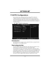
... select the SATA Spread Spectrum function. The Choices: Enable IF No Ext GPU (default). 18 PCIE Spread Spectrum This item allows you to select the CPU Spread Spectrum function. The Choices: Disabled (default), Linear Down. GF7050V-M7 Spread Spectrum Control CPU Spread Spectrum This item allows you to select the PCIE Spread Spectrum function.
... select the SATA Spread Spectrum function. The Choices: Enable IF No Ext GPU (default). 18 PCIE Spread Spectrum This item allows you to select the CPU Spread Spectrum function. The Choices: Disabled (default), Linear Down. GF7050V-M7 Spread Spectrum Control CPU Spread Spectrum This item allows you to select the PCIE Spread Spectrum function.

Bios Setup
Page 28
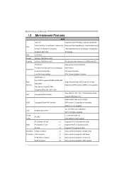
GF7050V-M7 Power Management This category allows you to select the power saving method and is directly related to 1 hr. Suspend Mode = 1 hr. The Choices: Disabled (default), 1 ... Mode = 1 min. HDD Power Down. 2. There are three options of Power Management, three of system inactivity. HDD Power Down = 15 min Max. except for sl CPU's. All other devices remain active. Video Off Method This option determines the manner when the monitor goes blank. HDD Power Down = 1 min. Suspend Mode. to...
GF7050V-M7 Power Management This category allows you to select the power saving method and is directly related to 1 hr. Suspend Mode = 1 hr. The Choices: Disabled (default), 1 ... Mode = 1 min. HDD Power Down. 2. There are three options of Power Management, three of system inactivity. HDD Power Down = 15 min Max. except for sl CPU's. All other devices remain active. Video Off Method This option determines the manner when the monitor goes blank. HDD Power Down = 1 min. Suspend Mode. to...
Bios Setup
Page 30
... the speed of the CPU itself uses when communicating with its own special components. PCI, or Personal Computer Interconnect, is called ESCD. Every peripheral device has a node, which is a system which resources are reserved in the system BIOS. This section covers some very technical items and it . GF7050V-M7 7 PnP/PCI Configurations This...
... the speed of the CPU itself uses when communicating with its own special components. PCI, or Personal Computer Interconnect, is called ESCD. Every peripheral device has a node, which is a system which resources are reserved in the system BIOS. This section covers some very technical items and it . GF7050V-M7 7 PnP/PCI Configurations This...
Bios Setup
Page 34
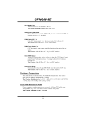
The Choices: Min=0,.Max=127, Key in a DEC number. Show H/W Monitor in POST If you computer contains a monitoring system, it will raise the speed of CPU fan. The Choices: Min=0,.Max=127, Key in a DEC number. The Choices: Min=1,.Max=127, Key in a DEC number. The item offers several different delay ...;, 90℃/ 167℉. Smart Fan Calibration Choose this item and then the BIOS will work under smart fan function when arrive this set value. GF7050V-M7 CPU Smart Fan This item allows you to work under Smart Fan Function mode. PWM Duty Start...
The Choices: Min=0,.Max=127, Key in a DEC number. Show H/W Monitor in POST If you computer contains a monitoring system, it will raise the speed of CPU fan. The Choices: Min=0,.Max=127, Key in a DEC number. The Choices: Min=1,.Max=127, Key in a DEC number. The item offers several different delay ...;, 90℃/ 167℉. Smart Fan Calibration Choose this item and then the BIOS will work under smart fan function when arrive this set value. GF7050V-M7 CPU Smart Fan This item allows you to work under Smart Fan Function mode. PWM Duty Start...

Bios Setup
Page 35
SYS FAN Speed This field displays the current speed SYSTEM fan. 34 CPU FAN Speed This field displays the current speed of CPU. CPU Temperature This field displays the current temperature of CPU fan. GF7050V-M7 CPU Vcore, NB Voltage, +3.3V, +5.0V, +12.0V, DDR Voltage, VTT Voltage, 5V(SB), Voltage Battery Detect the system's voltage status automatically.
SYS FAN Speed This field displays the current speed SYSTEM fan. 34 CPU FAN Speed This field displays the current speed of CPU. CPU Temperature This field displays the current temperature of CPU fan. GF7050V-M7 CPU Vcore, NB Voltage, +3.3V, +5.0V, +12.0V, DDR Voltage, VTT Voltage, 5V(SB), Voltage Battery Detect the system's voltage status automatically.

Setup Manual
Page 2
Table of Contents Chapter 1: Introduction 1 1.1 Before You Start 1 1.2 Package Checklist 1 1.3 Motherboard Features 2 1.4 Rear Panel Connectors 3 1.5 Motherboard Layout 4 Chapter 2: Hardware Installation 5 2.1 Installing Central Processing Unit (CPU 5 2.2 FAN Headers 7 2.3 Installing System Memory 8 2.4 Connectors and Slots 10 Chapter 3: Headers & Jumpers Setup 12 3.1 How to Setup Jumpers 12 3.2 Detail Settings 12 Chapter 4: RAID Functions ...
Table of Contents Chapter 1: Introduction 1 1.1 Before You Start 1 1.2 Package Checklist 1 1.3 Motherboard Features 2 1.4 Rear Panel Connectors 3 1.5 Motherboard Layout 4 Chapter 2: Hardware Installation 5 2.1 Installing Central Processing Unit (CPU 5 2.2 FAN Headers 7 2.3 Installing System Memory 8 2.4 Connectors and Slots 10 Chapter 3: Headers & Jumpers Setup 12 3.1 How to Setup Jumpers 12 3.2 Detail Settings 12 Chapter 4: RAID Functions ...
Setup Manual
Page 4
... / Execute Disable Bit / Intel Core2Duo / Core2Quad / Celeron 4xx / Enhanced Intel SpeedStep® / Intel Architecture-64 Pentium D / Pentium 4 processor / Extended Memory 64 Technology / Virtualization Supports 45nm CPU Technology 1333 MHz Chipset Graphics GeForce 7050/nForce 610i GeForce 7050/nForce 610i Max SharedVideo Memory is not supported Supports DDR2 533 / 667 / 800 IDE...
... / Execute Disable Bit / Intel Core2Duo / Core2Quad / Celeron 4xx / Enhanced Intel SpeedStep® / Intel Architecture-64 Pentium D / Pentium 4 processor / Extended Memory 64 Technology / Virtualization Supports 45nm CPU Technology 1333 MHz Chipset Graphics GeForce 7050/nForce 610i GeForce 7050/nForce 610i Max SharedVideo Memory is not supported Supports DDR2 533 / 667 / 800 IDE...
Setup Manual
Page 5
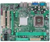
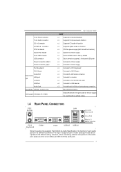
...Audio Jack BoardSize 185 (W) x 244 (L) mm OS Support Windows XP / VISTA GF7050V-M7 SPEC x1 Supports front panel facilities x1 Supports front panel audio function x1 Supports CD audio-in function x1 Supports digital audio out function x1 CPU Fan power supply (with or without notice. 1.4 REAR PANEL CONNECT ORS P S/...Connects to RJ-45 ethernet cable x4 Connects to USB devices x3 Provide Audio-In/Out and microphone connection Micro ATX form Factor Biostar Reserves the right to add or remove support for any OS with Smart Fan function) x1 System Fan Power supply x1 Restore ...
...Audio Jack BoardSize 185 (W) x 244 (L) mm OS Support Windows XP / VISTA GF7050V-M7 SPEC x1 Supports front panel facilities x1 Supports front panel audio function x1 Supports CD audio-in function x1 Supports digital audio out function x1 CPU Fan power supply (with or without notice. 1.4 REAR PANEL CONNECT ORS P S/...Connects to RJ-45 ethernet cable x4 Connects to USB devices x3 Provide Audio-In/Out and microphone connection Micro ATX form Factor Biostar Reserves the right to add or remove support for any OS with Smart Fan function) x1 System Fan Power supply x1 Restore ...

Setup Manual
Page 7
GF7050V-M7 CHAPTER 2: HARDWARE INSTALLATION 2.1 INST ALLING CENT RAL PROCESSING UNIT (CPU) Special Notice: Remove Pin Cap before installation, and make good preservation for future use. Pin-Cap Step 1: Pull the socket locking lever out from the socket and then raise the lever up to ensure pin legs won't be damaged. When the CPU is removed, cover the Pin Cap on the empty socket to a 90-degree angle. 5
GF7050V-M7 CHAPTER 2: HARDWARE INSTALLATION 2.1 INST ALLING CENT RAL PROCESSING UNIT (CPU) Special Notice: Remove Pin Cap before installation, and make good preservation for future use. Pin-Cap Step 1: Pull the socket locking lever out from the socket and then raise the lever up to ensure pin legs won't be damaged. When the CPU is removed, cover the Pin Cap on the empty socket to a 90-degree angle. 5

Setup Manual
Page 8
Step 4: Put the CPU Fan and heatsink assembly on the CPU and buckle it on CPU should point forwards this triangular cut edge on socket, and the golden dot on the retention frame. Connect the CPU FAN power cable into the JCFAN1. Step 2-1: Step 2-2: Step 3: Hold the CPU down firmly, and then lower the lever to locked position to complete the installation. The CPU will fit only in the correct orientation. This completes the installation. 6 Motherboard Manual Step 2: Look for the triangular cut edge.
Step 4: Put the CPU Fan and heatsink assembly on the CPU and buckle it on CPU should point forwards this triangular cut edge on socket, and the golden dot on the retention frame. Connect the CPU FAN power cable into the JCFAN1. Step 2-1: Step 2-2: Step 3: Hold the CPU down firmly, and then lower the lever to locked position to complete the installation. The CPU will fit only in the correct orientation. This completes the installation. 6 Motherboard Manual Step 2: Look for the triangular cut edge.

Setup Manual
Page 15
GF7050V-M7 JATXPWR1: ATX Powe r Source C onne ctor This connector allows user to CPU power circuit. 32 4 1 Pin Assignment 1 +12V 2 +12V 3 Ground 4 Ground Note: Befor e power on the ATX power supply. Pin Assignment 1 +3.3V 2 +3.3V 3 Ground 4 +5V 12 24 5 ...
GF7050V-M7 JATXPWR1: ATX Powe r Source C onne ctor This connector allows user to CPU power circuit. 32 4 1 Pin Assignment 1 +12V 2 +12V 3 Ground 4 Ground Note: Befor e power on the ATX power supply. Pin Assignment 1 +3.3V 2 +3.3V 3 Ground 4 +5V 12 24 5 ...
Setup Manual
Page 25
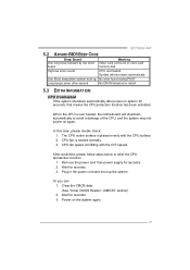
... system boot-up the system. Clear the CMOS data. (See "Close CMOS Header: JCMOS1" section) 2. When the CPU is fulfilling with the CPU surface. 2. Wait for seconds, that means the CPU protection function has been activated. GF7050V-M7 5.2 AWARD BIOS BEEP CODE Beep Sound One long beep followed by two short beeps Meaning Video card...
... system boot-up the system. Clear the CMOS data. (See "Close CMOS Header: JCMOS1" section) 2. When the CPU is fulfilling with the CPU surface. 2. Wait for seconds, that means the CPU protection function has been activated. GF7050V-M7 5.2 AWARD BIOS BEEP CODE Beep Sound One long beep followed by two short beeps Meaning Video card...


