Bios Setup
Page 2
...that it retains the Setup information when the power is to describe the settings in the Phoenix-Award™ BIOS Setup program on this motherboard. Plug and Play Support This PHOENIX-AWARD BIOS supports the Plug and Play Version 1.0A spec ification. APM Support This PHOENIX-AWARD ...without accessing programs from a disk. The Setup program allows users to modify the basic system configuration and save these settings to CMOS RAM. GF7050V-M7 BIOS Setup Introduction The purpose of this manual will to guide you through the options and settings in BIOS Setup. Some additional features, ...
...that it retains the Setup information when the power is to describe the settings in the Phoenix-Award™ BIOS Setup program on this motherboard. Plug and Play Support This PHOENIX-AWARD BIOS supports the Plug and Play Version 1.0A spec ification. APM Support This PHOENIX-AWARD ...without accessing programs from a disk. The Setup program allows users to modify the basic system configuration and save these settings to CMOS RAM. GF7050V-M7 BIOS Setup Introduction The purpose of this manual will to guide you through the options and settings in BIOS Setup. Some additional features, ...
Bios Setup
Page 22
... a DMA driver (Windows 95 or OSR2may need a third party IDE bus master driver). The Choices: Auto (default), Mode0, Mode1, Mode2, Mode3, Mode4. GF7050V-M7 On-chip IDE Channel 0 The motherboard chipset contains a PCI IDE interface with support for faster drive access. Select "Enabled" to activate the first and/or second IDE interface. The...
... a DMA driver (Windows 95 or OSR2may need a third party IDE bus master driver). The Choices: Auto (default), Mode0, Mode1, Mode2, Mode3, Mode4. GF7050V-M7 On-chip IDE Channel 0 The motherboard chipset contains a PCI IDE interface with support for faster drive access. Select "Enabled" to activate the first and/or second IDE interface. The...

Setup Manual
Page 2
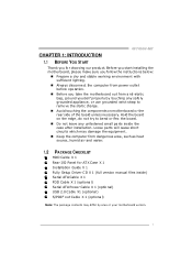
Table of Contents Chapter 1: Introduction 1 1.1 Before You Start 1 1.2 Package Checklist 1 1.3 Motherboard Features 2 1.4 Rear Panel Connectors 3 1.5 Motherboard Layout 4 Chapter 2: Hardware Installation 5 2.1 Installing Central Processing Unit (CPU 5 2.2 FAN Headers 7 2.3 Installing System Memory 8 2.4 Connectors and Slots 10 Chapter 3: Headers & Jumpers Setup 12 3.1 How to ...
Table of Contents Chapter 1: Introduction 1 1.1 Before You Start 1 1.2 Package Checklist 1 1.3 Motherboard Features 2 1.4 Rear Panel Connectors 3 1.5 Motherboard Layout 4 Chapter 2: Hardware Installation 5 2.1 Installing Central Processing Unit (CPU 5 2.2 FAN Headers 7 2.3 Installing System Memory 8 2.4 Connectors and Slots 10 Chapter 3: Headers & Jumpers Setup 12 3.1 How to ...
Setup Manual
Page 3
... compute r from dange rous a rea, such as hea t source , humid air and wate r. 1.2 PACKAGE CHECKLIST HDD Cable X 1 Rear I/O Panel for choosing our product. GF7050V-M7 CHAPTER 1: INTRODUCTION 1.1 BEFORE YOU START Thank you for ATX Case X 1 Installation Guide X 1 Fully Se tup Drive r C D X 1 (full ve rsion manual files inside...with sufficie nt lighting. „ Always disconne ct the compute r from anti-static bag, ground yourse lf prope rly by area or your motherboard version. 1 Be fore you start installing the mo the rboa rd, plea se make sure you take the mothe rboard out from powe r...
... compute r from dange rous a rea, such as hea t source , humid air and wate r. 1.2 PACKAGE CHECKLIST HDD Cable X 1 Rear I/O Panel for choosing our product. GF7050V-M7 CHAPTER 1: INTRODUCTION 1.1 BEFORE YOU START Thank you for ATX Case X 1 Installation Guide X 1 Fully Se tup Drive r C D X 1 (full ve rsion manual files inside...with sufficie nt lighting. „ Always disconne ct the compute r from anti-static bag, ground yourse lf prope rly by area or your motherboard version. 1 Be fore you start installing the mo the rboa rd, plea se make sure you take the mothe rboard out from powe r...
Setup Manual
Page 4
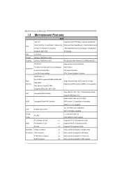
... Mode DDR2memory module Registered DIMM and ECC DIMM is 512MB(under OS) ITE 8718F Environment Control initiatives, Provides the most commonly usedlegacy Super I/O Super I/O functionality. Motherboard Manual 1.3 MOT HERBOARD FEAT URES SPEC CPU FSB LGA 775 Supports Hyper-Threading / Execute Disable Bit / Intel Core2Duo / Core2Quad / Celeron 4xx / Enhanced Intel SpeedStep®...
... Mode DDR2memory module Registered DIMM and ECC DIMM is 512MB(under OS) ITE 8718F Environment Control initiatives, Provides the most commonly usedlegacy Super I/O Super I/O functionality. Motherboard Manual 1.3 MOT HERBOARD FEAT URES SPEC CPU FSB LGA 775 Supports Hyper-Threading / Execute Disable Bit / Intel Core2Duo / Core2Quad / Celeron 4xx / Enhanced Intel SpeedStep®...
Setup Manual
Page 6
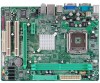
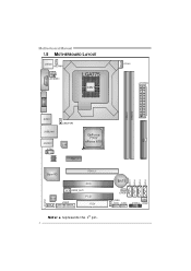
Motherboard Manual 1.5 MOT HERBOARD LAYOUT COMJC1OM1 JKB MS1 JKB_PWR1 JATXPWR3 LGA775 CPU1 JCFAN1 JATXPWR2 JV GA1 DIMMA1 DIMMA2 IDE1 JUSB1 JUSBLAN1 JUSB_PWR1 JAUDIO1 LAN JCDIN1 GeForce 7050/ nForce 610i PEX1_1 BIOS Super I/O PEX16_1 Co d ec PCI1 JSPDIF_OUT1 PCI2 JPRNT1 FDD1 SATA1 SATA2 SATA3 SATA4 BAT1 JCMOS1 JUSB_PWR2 JUSB2 JUSB3 JPANEL1 JSFAN1 JAUDIOF1 Not e: ■ repre sents the 1st pin. 4
Motherboard Manual 1.5 MOT HERBOARD LAYOUT COMJC1OM1 JKB MS1 JKB_PWR1 JATXPWR3 LGA775 CPU1 JCFAN1 JATXPWR2 JV GA1 DIMMA1 DIMMA2 IDE1 JUSB1 JUSBLAN1 JUSB_PWR1 JAUDIO1 LAN JCDIN1 GeForce 7050/ nForce 610i PEX1_1 BIOS Super I/O PEX16_1 Co d ec PCI1 JSPDIF_OUT1 PCI2 JPRNT1 FDD1 SATA1 SATA2 SATA3 SATA4 BAT1 JCMOS1 JUSB_PWR2 JUSB2 JUSB3 JPANEL1 JSFAN1 JAUDIOF1 Not e: ■ repre sents the 1st pin. 4

Setup Manual
Page 8
Connect the CPU FAN power cable into the JCFAN1. The CPU will fit only in the correct orientation. Step 2-1: Step 2-2: Step 3: Hold the CPU down firmly, and then lower the lever to locked position to complete the installation. Motherboard Manual Step 2: Look for the triangular cut edge. This completes the installation. 6 Step 4: Put the CPU Fan and heatsink assembly on the CPU and buckle it on CPU should point forwards this triangular cut edge on socket, and the golden dot on the retention frame.
Connect the CPU FAN power cable into the JCFAN1. The CPU will fit only in the correct orientation. Step 2-1: Step 2-2: Step 3: Hold the CPU down firmly, and then lower the lever to locked position to complete the installation. Motherboard Manual Step 2: Look for the triangular cut edge. This completes the installation. 6 Step 4: Put the CPU Fan and heatsink assembly on the CPU and buckle it on CPU should point forwards this triangular cut edge on socket, and the golden dot on the retention frame.

Setup Manual
Page 10
D IMMA1 D IMMA2 Motherboard Manual 2.3 INST ALLING SYST EM MEMORY A. Unlock a DIMM slot by pressing the retaining clips outward. Align a DIMM on the slot such that the notch on the DIMM matches the break on the Slot. 8 Memory Modules 1.
D IMMA1 D IMMA2 Motherboard Manual 2.3 INST ALLING SYST EM MEMORY A. Unlock a DIMM slot by pressing the retaining clips outward. Align a DIMM on the slot such that the notch on the DIMM matches the break on the Slot. 8 Memory Modules 1.

Setup Manual
Page 12
Motherboard Manual 2.4 CONNECT ORS AND SLOT S FDD1: Floppy Disk Conne ctor The motherboard prov ides a standard floppy disk connector that prov ides PIO Mode 0~4, Bus Master, and Ultra DMA 33/66/100/133 f unctionality. The IDE connector can connect a master and a slave drive, so y ou can connect up to two hard disk driv es. 40 39 2 1 10 This connector supports the prov ided f loppy drive ribbon cables. 2 34 1 33 IDE1: Hard Disk Conne ctor The motherboard has a 32-bit Enhanced PCI IDE Controller that supports 360K, 720K, 1.2M, 1.44M and 2.88M floppy disk ty pes.
Motherboard Manual 2.4 CONNECT ORS AND SLOT S FDD1: Floppy Disk Conne ctor The motherboard prov ides a standard floppy disk connector that prov ides PIO Mode 0~4, Bus Master, and Ultra DMA 33/66/100/133 f unctionality. The IDE connector can connect a master and a slave drive, so y ou can connect up to two hard disk driv es. 40 39 2 1 10 This connector supports the prov ided f loppy drive ribbon cables. 2 34 1 33 IDE1: Hard Disk Conne ctor The motherboard has a 32-bit Enhanced PCI IDE Controller that supports 360K, 720K, 1.2M, 1.44M and 2.88M floppy disk ty pes.
Setup Manual
Page 13
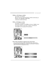
... the traditional PCI architecture. PCI1 PCI2 11 PCI stands for expansion cards. GF7050V-M7 PEX16_1: PCI-Express x16 Slot - PEX1_1: PCI-Expre ss x1 Slot - PCI-Express 1.0a compliant. - PEX1 _1 PEX16_1 PCI1~PCI2: Pe riphe ral Component Interconne ct Slots The motherboard is equipped with 2 standard PCI slots. PCI-Express 1.0a compliant. -
... the traditional PCI architecture. PCI1 PCI2 11 PCI stands for expansion cards. GF7050V-M7 PEX16_1: PCI-Express x16 Slot - PEX1_1: PCI-Expre ss x1 Slot - PCI-Express 1.0a compliant. - PEX1 _1 PEX16_1 PCI1~PCI2: Pe riphe ral Component Interconne ct Slots The motherboard is equipped with 2 standard PCI slots. PCI-Express 1.0a compliant. -
Setup Manual
Page 14
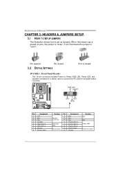
Motherboard Manual CHAPTER 3: HEADERS & JUMPERS SETUP 3.1 HOW T O SET UP JUMPERS The illustration shows how to connect the PC case's f ront panel switch f unctions. When the jumper ...
Motherboard Manual CHAPTER 3: HEADERS & JUMPERS SETUP 3.1 HOW T O SET UP JUMPERS The illustration shows how to connect the PC case's f ront panel switch f unctions. When the jumper ...

Setup Manual
Page 16
... SATA 2 SATA3 S ATA4 1 4 7 Pin Assignment 1 Ground 2 TX+ 3 TX4 Ground 5 RX6 RX+ 7 Ground 14 Motherboard Manual JUSB2/JUSB3: Heade rs for USB 2.0 Ports at Front Panel This motherboard prov ides 2 USB 2.0 headers, which allows user to SATA Controller with 4 channels SATA interf ace, it satisfies the SATA 2.0 spec...1 9 Pin Assignment 1 +5V (fused) 2 +5V (fused) 3 USB4 USB5 USB+ 6 USB+ 7 Ground 8 Ground 9 Key 10 NC SATA1~SATA4: Se rial ATA Connectors The motherboard has a PCI to connect additional USB cable on the PC front panel, and also can be connected with transfer rate of 3Gb/s.
... SATA 2 SATA3 S ATA4 1 4 7 Pin Assignment 1 Ground 2 TX+ 3 TX4 Ground 5 RX6 RX+ 7 Ground 14 Motherboard Manual JUSB2/JUSB3: Heade rs for USB 2.0 Ports at Front Panel This motherboard prov ides 2 USB 2.0 headers, which allows user to SATA Controller with 4 channels SATA interf ace, it satisfies the SATA 2.0 spec...1 9 Pin Assignment 1 +5V (fused) 2 +5V (fused) 3 USB4 USB5 USB+ 6 USB+ 7 Ground 8 Ground 9 Key 10 NC SATA1~SATA4: Se rial ATA Connectors The motherboard has a PCI to connect additional USB cable on the PC front panel, and also can be connected with transfer rate of 3Gb/s.

Setup Manual
Page 18
... Pin 1-2 Close: Normal Operation (Default). 13 13 Pin 2-3 Close: Clear CMOS data. ※ Clear CMOS Proce dures: 1. Motherboard Manual JCDIN1: CD-RO M Audio-in Connector This connector allows user to connect the audio source f rom the variaty dev ices, like CD-ROM, DVD-...
... Pin 1-2 Close: Normal Operation (Default). 13 13 Pin 2-3 Close: Clear CMOS data. ※ Clear CMOS Proce dures: 1. Motherboard Manual JCDIN1: CD-RO M Audio-in Connector This connector allows user to connect the audio source f rom the variaty dev ices, like CD-ROM, DVD-...

Setup Manual
Page 20
Pin Assignment 1 -Strobe 2 -ALF 3 Data 0 4 -Error 5 Data 1 6 -Init 7 Data 2 8 -Scltin 9 Data 3 10 Ground 11 Data 4 12 Ground 13 Data 5 2 1 25 Pin Assignment 14 Ground 15 Data 6 16 Ground 17 Data 7 18 Ground 19 -ACK 20 Ground 21 Busy 22 Ground 23 PE 24 Ground 25 SCLT 26 Key 18 Motherboard Manual JPRNT1: Printe r Port Connector This header allows you to connector printer on the PC.
Pin Assignment 1 -Strobe 2 -ALF 3 Data 0 4 -Error 5 Data 1 6 -Init 7 Data 2 8 -Scltin 9 Data 3 10 Ground 11 Data 4 12 Ground 13 Data 5 2 1 25 Pin Assignment 14 Ground 15 Data 6 16 Ground 17 Data 7 18 Ground 19 -ACK 20 Ground 21 Busy 22 Ground 23 PE 24 Ground 25 SCLT 26 Key 18 Motherboard Manual JPRNT1: Printe r Port Connector This header allows you to connector printer on the PC.

Setup Manual
Page 22
... any other drive. Drawbacks: Requires 2 driv es for high-availability solutions, or as a form of a hardware failure. Block 1 Block 2 Block 3 20 Block 1 Block 2 Block 3 Motherboard Manual RAID 1: Every read and write is actually carried out in parallel across 2 disk drives in the array. Should one driv e f ail, the controller switches...
... any other drive. Drawbacks: Requires 2 driv es for high-availability solutions, or as a form of a hardware failure. Block 1 Block 2 Block 3 20 Block 1 Block 2 Block 3 Motherboard Manual RAID 1: Every read and write is actually carried out in parallel across 2 disk drives in the array. Should one driv e f ail, the controller switches...

Setup Manual
Page 24
...Driver CD, please use file brows er to launch the installation program. A. Manual Aside from http://www.adobe.com/products/acrobat/readstep 2.html 22 Motherboard Manual CHAPTER 5: USEFUL HELP 5.1 DRIVER INST ALLAT ION NOT E After you installed your operating system, please insert the Fully Setup Driver CD into... your optical drive and install the driver for available manual. Note: You will list the compatible driver for your motherboard and operating system. Note: If this window didn't show up after you insert the CD T he setup guide will list the software ...
...Driver CD, please use file brows er to launch the installation program. A. Manual Aside from http://www.adobe.com/products/acrobat/readstep 2.html 22 Motherboard Manual CHAPTER 5: USEFUL HELP 5.1 DRIVER INST ALLAT ION NOT E After you installed your operating system, please insert the Fully Setup Driver CD into... your optical drive and install the driver for available manual. Note: You will list the compatible driver for your motherboard and operating system. Note: If this window didn't show up after you insert the CD T he setup guide will list the software ...
Setup Manual
Page 25
... fulfilling with the CPU surface. 2. After confirmed, please follow steps below to avoid a damage of the CPU, and the system may not power on again. GF7050V-M7 5.2 AWARD BIOS BEEP CODE Beep Sound One long beep followed by two short beeps Meaning Video card not found during POST Long beeps every other... the CPU protection function has been activated. In this case, please double check: 1. Power on system for seconds. 3. CPU fan speed is over heated, the motherboard will shut down automatically One Short beep when system boot-up the system.
... fulfilling with the CPU surface. 2. After confirmed, please follow steps below to avoid a damage of the CPU, and the system may not power on again. GF7050V-M7 5.2 AWARD BIOS BEEP CODE Beep Sound One long beep followed by two short beeps Meaning Video card not found during POST Long beeps every other... the CPU protection function has been activated. In this case, please double check: 1. Power on system for seconds. 3. CPU fan speed is over heated, the motherboard will shut down automatically One Short beep when system boot-up the system.

Setup Manual
Page 26
... hard disks are lit, and hard driv e is impossible. Keyboard lights are on . 3. Rev iew system's equipment. Cannot boot system after installing second hard driv e. 1. Motherboard Manual 5.4 TROUBLESHOOT ING Probable Solution 1. driv e, can be booted f rom optical driv e. 2. check the driv e type in . Set master/slave jumpers correctly. 2. Call the drive...
... hard disks are lit, and hard driv e is impossible. Keyboard lights are on . 3. Rev iew system's equipment. Cannot boot system after installing second hard driv e. 1. Motherboard Manual 5.4 TROUBLESHOOT ING Probable Solution 1. driv e, can be booted f rom optical driv e. 2. check the driv e type in . Set master/slave jumpers correctly. 2. Call the drive...

