Bios Setup
Page 1
G31-M7/P31-A7 BIOS Manual Table of Contents BIOS Setup ...1 1 Main Menu ...3 2 Standard CMOS Features...6 3 Advanced BIOS Features ...8 4 Advanced Chipset Features...14 5 Integrated Peripherals...17 6 Power Management Setup...23 7 PnP/PCI Configurations...29 8 PC Health Status ...32 9 Performance Booster Zone...35
G31-M7/P31-A7 BIOS Manual Table of Contents BIOS Setup ...1 1 Main Menu ...3 2 Standard CMOS Features...6 3 Advanced BIOS Features ...8 4 Advanced Chipset Features...14 5 Integrated Peripherals...17 6 Power Management Setup...23 7 PnP/PCI Configurations...29 8 PC Health Status ...32 9 Performance Booster Zone...35
Bios Setup
Page 2
... executing the operating system. Plug and Play Support This PHOENIX-AWARD BIOS supports the Plug and Play Version 1.0A specification. G31-M7/P31-A7 BIOS Setup Introduction The purpose of this manual is to describe the settings in BIOS Setup. The rest of the Advanced Power Management (APM) specification.... Power to CMOS RAM. BIOS activates at the first stage of the input...
... executing the operating system. Plug and Play Support This PHOENIX-AWARD BIOS supports the Plug and Play Version 1.0A specification. G31-M7/P31-A7 BIOS Setup Introduction The purpose of this manual is to describe the settings in BIOS Setup. The rest of the Advanced Power Management (APM) specification.... Power to CMOS RAM. BIOS activates at the first stage of the input...
Bios Setup
Page 3
...item on the left (menu bar) Move to highlight items in the ACPI specification, developed by using the keyboard. G31-M7/P31-A7 ACPI Support Phoenix-Award ACPI BIOS support Version 1.0b of the Intel PCI (Peripheral Component Interconnect) local bus specification. The following table provides more detail... help and press to navigate in the Setup program by Microsoft, Intel and Toshiba. Supported CPUs This PHOENIX-AWARD BIOS supports the Intel CPU. PCI Bus Support This PHOENIX-AWARD BIOS also supports Version 2.3 of Advanced Configuration and Power interface specification (ACPI).
...item on the left (menu bar) Move to highlight items in the ACPI specification, developed by using the keyboard. G31-M7/P31-A7 ACPI Support Phoenix-Award ACPI BIOS support Version 1.0b of the Intel PCI (Peripheral Component Interconnect) local bus specification. The following table provides more detail... help and press to navigate in the Setup program by Microsoft, Intel and Toshiba. Supported CPUs This PHOENIX-AWARD BIOS supports the Intel CPU. PCI Bus Support This PHOENIX-AWARD BIOS also supports Version 2.3 of Advanced Configuration and Power interface specification (ACPI).
Bios Setup
Page 4
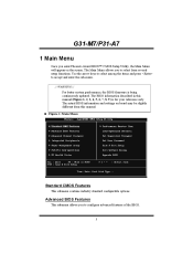
...board may be slightly different from several setup functions. The BIOS information described in this manual. „ Figure 1: Main Menu Standard CMOS Features This submenu contains industry standard configurable options. G31-M7/P31-A7 1 Main Menu Once you to configure advanced ...features of the BIOS. 3 Use the arrow keys to select among the items and press to select from this manual (Figure 1, ...
...board may be slightly different from several setup functions. The BIOS information described in this manual. „ Figure 1: Main Menu Standard CMOS Features This submenu contains industry standard configurable options. G31-M7/P31-A7 1 Main Menu Once you to configure advanced ...features of the BIOS. 3 Use the arrow keys to select among the items and press to select from this manual (Figure 1, ...
Bios Setup
Page 5
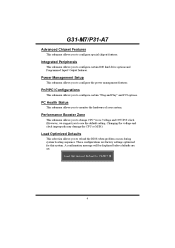
... Peripherals This submenu allows you to reload the BIOS when problem occurs during system booting sequence. Power Management Setup This submenu allows you to configure special chipset features. A confirmation message will be displayed before defaults are factory settings optimized for this system. G31-M7/P31-A7 Advanced Chipset Features This submenu allows you...
... Peripherals This submenu allows you to reload the BIOS when problem occurs during system booting sequence. Power Management Setup This submenu allows you to configure special chipset features. A confirmation message will be displayed before defaults are factory settings optimized for this system. G31-M7/P31-A7 Advanced Chipset Features This submenu allows you...
Bios Setup
Page 6
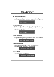
... password. Save & Exit Setup Save all changes made during the current session and exit setup. G31-M7/P31-A7 Set Supervisor Password Setting the supervisor password will be able to change them. Upgrade BIOS This submenu allows you to CMOS (memory) and exit setup. If the Supervisor Password is set... will be displayed before proceeding. Confirmation message will be displayed before proceeding. Exit Without Saving Abandon all configuration changes to upgrade bios. 5 You will prohibit everyone except the supervisor from making changes using the CMOS Setup Utility.
... password. Save & Exit Setup Save all changes made during the current session and exit setup. G31-M7/P31-A7 Set Supervisor Password Setting the supervisor password will be able to change them. Upgrade BIOS This submenu allows you to CMOS (memory) and exit setup. If the Supervisor Password is set... will be displayed before proceeding. Confirmation message will be displayed before proceeding. Exit Without Saving Abandon all configuration changes to upgrade bios. 5 You will prohibit everyone except the supervisor from making changes using the CMOS Setup Utility.

Bios Setup
Page 8
... drive installed in which you want the BIOS to stop the POST process and notify you. Description Extended Memory Total Memory N/A N/A 7 Displays the amount of extended memory detected during boot up . Select the situation in your system. Displays the total memory available in the system. G31-M7/P31-A7 Item Options None 360K...
... drive installed in which you want the BIOS to stop the POST process and notify you. Description Extended Memory Total Memory N/A N/A 7 Displays the amount of extended memory detected during boot up . Select the situation in your system. Displays the total memory available in the system. G31-M7/P31-A7 Item Options None 360K...

Bios Setup
Page 9
... for Hyper-Threading Technology). "Enabled" for Windows XP and Linux 2.4.x (OS optimized for Hyper-Threading Technology). The Choices: Enabled (default), Disabled. 8 G31-M7/P31-A7 3 Advanced BIOS Features „ Figure 3: Advanced BIOS Setup Virus Warning This option allows you to protect the IDE Hard Disk boot sector. Disabled (default) Virus protection is activated. Enabled...
... for Hyper-Threading Technology). "Enabled" for Windows XP and Linux 2.4.x (OS optimized for Hyper-Threading Technology). The Choices: Enabled (default), Disabled. 8 G31-M7/P31-A7 3 Advanced BIOS Features „ Figure 3: Advanced BIOS Setup Virus Warning This option allows you to protect the IDE Hard Disk boot sector. Disabled (default) Virus protection is activated. Enabled...

Bios Setup
Page 11
... enable/disable the summary screen. Summary Screen Show This item allows you to select whether the "Small Logo" shows. MPS Version Control For OS The BIOS supports version 1.1 and 1.4 of the Intel multiprocessor specification. Summary screen means system configuration and PCI device listing. System: A password is required for the ... the operation system running on this computer. The Choices: Non-OS2 (default), OS2. Setup (default): A password is required to access the Setup Utility only. G31-M7/P31-A7 Security Option This option will only apply if passwords are set from the...
... enable/disable the summary screen. Summary Screen Show This item allows you to select whether the "Small Logo" shows. MPS Version Control For OS The BIOS supports version 1.1 and 1.4 of the Intel multiprocessor specification. Summary screen means system configuration and PCI device listing. System: A password is required for the ... the operation system running on this computer. The Choices: Non-OS2 (default), OS2. Setup (default): A password is required to access the Setup Utility only. G31-M7/P31-A7 Security Option This option will only apply if passwords are set from the...

Bios Setup
Page 13
G31-M7/P31-A7 Boot Seq & Floppy Setup This item allows you to arrange the Hard Disk boot sequence automatically.You can change the Hard Disk booting sequence here. Master, Pri. Master, Sec. Slave, USB HDD0, USB HDD1, USB HDD2 and Bootable Add-in Cards. 12 Slave, Sec. The Choices: Pri. Hard Disk Boot Priority The BIOS will attempt to setup boot sequence & Floppy.
G31-M7/P31-A7 Boot Seq & Floppy Setup This item allows you to arrange the Hard Disk boot sequence automatically.You can change the Hard Disk booting sequence here. Master, Pri. Master, Sec. Slave, USB HDD0, USB HDD1, USB HDD2 and Bootable Add-in Cards. 12 Slave, Sec. The Choices: Pri. Hard Disk Boot Priority The BIOS will attempt to setup boot sequence & Floppy.

Bios Setup
Page 14
... the operating system from other device when it takes to load from the three devices above. The Choices: Enabled (default), Disabled. G31-M7/P31-A7 First/Second/Third Boot Device The BIOS will attempt to swap logical drive assignments. The Choices: Enabled (default), Disabled Swap Floppy Drive For systems with two floppy drives...
... the operating system from other device when it takes to load from the three devices above. The Choices: Enabled (default), Disabled. G31-M7/P31-A7 First/Second/Third Boot Device The BIOS will attempt to swap logical drive assignments. The Choices: Enabled (default), Disabled Swap Floppy Drive For systems with two floppy drives...

Bios Setup
Page 15
... Selecting the "Enabled" option allows caching of the system BIOS ROM at F0000h-FFFFFh, which is able to improve the system performance. The Choices: Disabled (default), Enabled. 14 However, any programs that attempts to write to system memory resources, such as DRAM. G31-M7/P31-A7 4 Advanced Chipset Features This submenu allows you...
... Selecting the "Enabled" option allows caching of the system BIOS ROM at F0000h-FFFFFh, which is able to improve the system performance. The Choices: Disabled (default), Enabled. 14 However, any programs that attempts to write to system memory resources, such as DRAM. G31-M7/P31-A7 4 Advanced Chipset Features This submenu allows you...
Bios Setup
Page 19
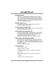
...PATA max of 6 IDE drivers are combined max of 2 IDE drivers in each device. The Choices: Enabled (default), Disabled. Modes 0 to enable BIOS support. The Choices: Enabled (default), Disabled. IDE Primary/Secondary Master/Slave PIO The IDE PIO (Programmed Input / Output) fields let you to ...enable or disable the IDE DMA transfer access. Enhanced Mode: enabled both support Ultra DMA, select Auto to 4 will increase performance progressively. G31-M7/P31-A7 IDE HDD Block Mode Block mode is operating in legacy mode. 18 The Choices: Auto (default), Disabled. As well, your ...
...PATA max of 6 IDE drivers are combined max of 2 IDE drivers in each device. The Choices: Enabled (default), Disabled. Modes 0 to enable BIOS support. The Choices: Enabled (default), Disabled. IDE Primary/Secondary Master/Slave PIO The IDE PIO (Programmed Input / Output) fields let you to ...enable or disable the IDE DMA transfer access. Enhanced Mode: enabled both support Ultra DMA, select Auto to 4 will increase performance progressively. G31-M7/P31-A7 IDE HDD Block Mode Block mode is operating in legacy mode. 18 The Choices: Auto (default), Disabled. As well, your ...

Bios Setup
Page 22
...1.0/2.0 Controller This entry is SPP. G31-M7/P31-A7 Parallel Port Mode This item allows you to enabled/ disabled EHCI controller only. EPP Using Parallel Port as ECP & EPP mode. ECP Mode Use DMA Select a DMA Channel for the port. If the Bios has high speed USB support built ...Using Parallel port as Enhanced Parallel Port. The Choices: SPP (default) Using Parallel port as Extended Capabilities Port. The Choices: 3 (default), 1. This Bios itself may/may not have high speed USB support. ECP Using Parallel port as Standard Printer Port. The default value is to determine how the...
...1.0/2.0 Controller This entry is SPP. G31-M7/P31-A7 Parallel Port Mode This item allows you to enabled/ disabled EHCI controller only. EPP Using Parallel Port as ECP & EPP mode. ECP Mode Use DMA Select a DMA Channel for the port. If the Bios has high speed USB support built ...Using Parallel port as Enhanced Parallel Port. The Choices: SPP (default) Using Parallel port as Extended Capabilities Port. The Choices: 3 (default), 1. This Bios itself may/may not have high speed USB support. ECP Using Parallel port as Standard Printer Port. The default value is to determine how the...
Bios Setup
Page 25
... after S3. Suspend Mode. HDD Power Down = 15 min Max. When you choose user define, you disable the function, but system will make BIOS run VGA BIOS to initialize the VGA card when system wakes up from 1 min. The Choices: Auto (default), Yes, No. There are three options of Power... modes: 1. Power Saving (default) Maximum power management only available for HDD Power Down which have fixed mode settings Min. to 15 min. 24 G31-M7/P31-A7 Run VGABIOS if S3 Resume Choosing Enabled will need AGP driver to initialize the card. to 1 hr. Power Saving Minimum power management.
... after S3. Suspend Mode. HDD Power Down = 15 min Max. When you choose user define, you disable the function, but system will make BIOS run VGA BIOS to initialize the VGA card when system wakes up from 1 min. The Choices: Auto (default), Yes, No. There are three options of Power... modes: 1. Power Saving (default) Maximum power management only available for HDD Power Down which have fixed mode settings Min. to 15 min. 24 G31-M7/P31-A7 Run VGABIOS if S3 Resume Choosing Enabled will need AGP driver to initialize the card. to 1 hr. Power Saving Minimum power management.
Bios Setup
Page 31
... update only when the new configuration varies from conflict. Be sure that there are reserved in the system BIOS. Every peripheral device has a node, which resources are assigned and protects resources from the last one. If the Disabled (default) option is chosen, the system's ... need to assign IRQ & DMA for add-on the screen only if "Manual" is chosen for ISA PnP add-on cards. G31-M7/P31-A7 Reset Configuration Data The system BIOS supports the PnP feature which requires the system to record which signifies that a resource is assigned to the ISA Bus and provides...
... update only when the new configuration varies from conflict. Be sure that there are reserved in the system BIOS. Every peripheral device has a node, which resources are assigned and protects resources from the last one. If the Disabled (default) option is chosen, the system's ... need to assign IRQ & DMA for add-on the screen only if "Manual" is chosen for ISA PnP add-on cards. G31-M7/P31-A7 Reset Configuration Data The system BIOS supports the PnP feature which requires the system to record which signifies that a resource is assigned to the ISA Bus and provides...

Bios Setup
Page 34
..., +5.0V, +12.0V, DDR Voltage, FSB Voltage, Voltage Battery Detect the system's voltage status automatically. 33 The Choices: Min=0,.Max=127, Key in a DEC number. G31-M7/P31-A7 CPU Smart Fan This item allows you to set up the CPU shutdown Temperature. Smart Fan Calibration PWM Duty Off PWM Duty Start... of CPU fan. Smart Fan Slope Shutdown Temperature This item allows you to work under smart fan function when arrive this item and then the BIOS will auto test and detect the CPU fan functions and show PC health status during POST stage. The Choices: Min=1,.Max=127, Key in ...
..., +5.0V, +12.0V, DDR Voltage, FSB Voltage, Voltage Battery Detect the system's voltage status automatically. 33 The Choices: Min=0,.Max=127, Key in a DEC number. G31-M7/P31-A7 CPU Smart Fan This item allows you to set up the CPU shutdown Temperature. Smart Fan Calibration PWM Duty Off PWM Duty Start... of CPU fan. Smart Fan Slope Shutdown Temperature This item allows you to work under smart fan function when arrive this item and then the BIOS will auto test and detect the CPU fan functions and show PC health status during POST stage. The Choices: Min=1,.Max=127, Key in ...
Setup Manual
Page 2
... & Jumpers Setup 12 3.1 How to Setup Jumpers 12 3.2 Detail Settings 12 Chapter 4: Useful Help 18 4.1 Driver Installation Note 18 4.2 Software 19 4.3 Extra Information 24 4.4 AMI BIOS Beep Code 26 4.5 Troubleshooting 27 Appendix: SPEC In Other Language 28 German...28 France ...30 Italian...32 Spanish ...34 Portuguese ...36 Polish...38 Russian ...40...
... & Jumpers Setup 12 3.1 How to Setup Jumpers 12 3.2 Detail Settings 12 Chapter 4: Useful Help 18 4.1 Driver Installation Note 18 4.2 Software 19 4.3 Extra Information 24 4.4 AMI BIOS Beep Code 26 4.5 Troubleshooting 27 Appendix: SPEC In Other Language 28 German...28 France ...30 Italian...32 Spanish ...34 Portuguese ...36 Polish...38 Russian ...40...

Setup Manual
Page 6
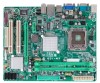
Motherboard Manual 1.5 MOTHERBOARD LAYOUT JKBMS1 JATXPWR2 LGA775 CPU1 JCFAN1 JATXPWR1 DDR2_A1 DDR2_B1 JVGA1 JUSBV1 JUSB2 JRJ45USB1 I nt el G31 IDE1 JAUDIO1 BIOS JAUDIOF1 LAN BATTERY PEX16_1 Super I/O Codec PCI1 JPRNT1 PCI2 JCOM2 Intel ICH7 JUSB3 FDD1 JSFAN1 JUSB4 JPANEL1 JCMOS1 SATA1 SATA2 Note: ■ represents the 1st pin. SATA4 SATA3 4
Motherboard Manual 1.5 MOTHERBOARD LAYOUT JKBMS1 JATXPWR2 LGA775 CPU1 JCFAN1 JATXPWR1 DDR2_A1 DDR2_B1 JVGA1 JUSBV1 JUSB2 JRJ45USB1 I nt el G31 IDE1 JAUDIO1 BIOS JAUDIOF1 LAN BATTERY PEX16_1 Super I/O Codec PCI1 JPRNT1 PCI2 JCOM2 Intel ICH7 JUSB3 FDD1 JSFAN1 JUSB4 JPANEL1 JCMOS1 SATA1 SATA2 Note: ■ represents the 1st pin. SATA4 SATA3 4

Setup Manual
Page 17
.../s. SATA1~SATA4: Serial ATA Connectors The motherboard has a PCI to SATA Controller with 4channels SATA interface, it allows user to restore the BIOS safe setting and the CMOS data, please carefully follow the procedures to "Pin 2-3 close ". 5. Wait for five seconds. 4. Set...: Normal Operation (Default). 3 1 3 1 Pin 2-3 Close: Clear CMOS data. ※ Clear CMOS Procedures: 1. Reset your desired password or clear the CMOS data. G31-M7 OC JCMOS1: Clear CMOS Header By placing the jumper on the AC. 6. SATA4 SATA3 SATA1 SATA2 Pin Assignment 1 Ground 2 TX+ 3 TX4 Ground 5 RX6 RX+ ...
.../s. SATA1~SATA4: Serial ATA Connectors The motherboard has a PCI to SATA Controller with 4channels SATA interface, it allows user to restore the BIOS safe setting and the CMOS data, please carefully follow the procedures to "Pin 2-3 close ". 5. Wait for five seconds. 4. Set...: Normal Operation (Default). 3 1 3 1 Pin 2-3 Close: Clear CMOS data. ※ Clear CMOS Procedures: 1. Reset your desired password or clear the CMOS data. G31-M7 OC JCMOS1: Clear CMOS Header By placing the jumper on the AC. 6. SATA4 SATA3 SATA1 SATA2 Pin Assignment 1 Ground 2 TX+ 3 TX4 Ground 5 RX6 RX+ ...

