
Setup Manual
Page 2
... 3 1.1 Before You Start 3 1.2 Package Checklist 3 1.3 Motherboard Features 4 1.4 Rear Panel Connectors 6 1.5 Motherboard Layout 7 Chapter 2: Hardware Installation 8 2.1 Installing Central Processing Unit (CPU 8 2.2 FAN Headers 10 2.3 Installing System Memory 11 2.4 Connectors and Slots 13 Chapter 3: Headers & Jumpers Setup 15 3.1 How to Setup Jumpers 15 3.2 Detail Settings 15 Chapter 4: RAID Functions 22 4.1 Operation System 22...
... 3 1.1 Before You Start 3 1.2 Package Checklist 3 1.3 Motherboard Features 4 1.4 Rear Panel Connectors 6 1.5 Motherboard Layout 7 Chapter 2: Hardware Installation 8 2.1 Installing Central Processing Unit (CPU 8 2.2 FAN Headers 10 2.3 Installing System Memory 11 2.4 Connectors and Slots 13 Chapter 3: Headers & Jumpers Setup 15 3.1 How to Setup Jumpers 15 3.2 Detail Settings 15 Chapter 4: RAID Functions 22 4.1 Operation System 22...
Setup Manual
Page 4
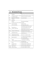
... used legacy H/W Monitor Super I/O Super I/O functionality. Fan Speed Controller Low Pin Count Interface ITE's "Smart Guardian" function Main Memory DDR2 DIMM Slots x 4 Max Memory Capacity 4GB Graphics Integrated in AMD 690G (for HDMI Audio) Integrated in AMD 690G Chipset Each DIMM supports 256/512MB & 1GB DDR2... Dual Channel Mode DDR2 memory module Supports DDR2 400/ 533 / 667 / 800 Registered DIMM and ECC DIMM is not supported Max Shared Video Memory is 512MB IDE Integrated IDE Controller Ultra DMA 33 / 66 / 100 / 133...
... used legacy H/W Monitor Super I/O Super I/O functionality. Fan Speed Controller Low Pin Count Interface ITE's "Smart Guardian" function Main Memory DDR2 DIMM Slots x 4 Max Memory Capacity 4GB Graphics Integrated in AMD 690G (for HDMI Audio) Integrated in AMD 690G Chipset Each DIMM supports 256/512MB & 1GB DDR2... Dual Channel Mode DDR2 memory module Supports DDR2 400/ 533 / 667 / 800 Registered DIMM and ECC DIMM is not supported Max Shared Video Memory is 512MB IDE Integrated IDE Controller Ultra DMA 33 / 66 / 100 / 133...
Setup Manual
Page 11
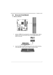
Memory Modules TA690G AM2 DIMMA1 DIMMB1 DIMMA2 DIMMB2 1. Unlock a DIMM slot by pressing the retaining clips outward. Insert the DIMM vertically and firmly into the slot until the retaining chip snap back in place and the DIMM is properly seated. 11 2.3 INSTALLING SYSTEM MEMORY A. Align a DIMM on the slot such that the notch on the DIMM matches the break on the Slot. 2.
Memory Modules TA690G AM2 DIMMA1 DIMMB1 DIMMA2 DIMMB2 1. Unlock a DIMM slot by pressing the retaining clips outward. Insert the DIMM vertically and firmly into the slot until the retaining chip snap back in place and the DIMM is properly seated. 11 2.3 INSTALLING SYSTEM MEMORY A. Align a DIMM on the slot such that the notch on the DIMM matches the break on the Slot. 2.

Setup Manual
Page 12
... DIMMA1 DIMMB1 DIMMA2 DIMMB2 Enabled O O X X Enabled X X O O Enabled O O O O (O means memory installed, X means memory not installed.) The DRAM bus width of the memory module must meet the following requirements: Install memory module of the motherboard, the memory module must be the same (x8 or x16) 12 C. Dual Channel Memory installation To trigger the Dual Channel function of the...
... DIMMA1 DIMMB1 DIMMA2 DIMMB2 Enabled O O X X Enabled X X O O Enabled O O O O (O means memory installed, X means memory not installed.) The DRAM bus width of the memory module must meet the following requirements: Install memory module of the motherboard, the memory module must be the same (x8 or x16) 12 C. Dual Channel Memory installation To trigger the Dual Channel function of the...
Setup Manual
Page 21
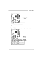
TA690G AM2 RSTSW1 PWRSW1 PWRSW1: This is an on-board Reset button. On-Board LED Indicators There are 2 on-board buttons. Please refer to show system status. RSTSW1: This is an on-board Power Switch button. On-Board Buttons There are 2 LED indicators on the motherboard to the table below for different messages: LED_D1 ON ON OFF OFF LED_D2 ON OFF ON OFF Message Normal Memory Error VGA Error Abnormal: CPU / Chipset error. 21 LED_D1 LED_D2 LED_D1 and LED_D2: These 2 LED indicate system power on diagnostics.
TA690G AM2 RSTSW1 PWRSW1 PWRSW1: This is an on-board Reset button. On-Board LED Indicators There are 2 on-board buttons. Please refer to show system status. RSTSW1: This is an on-board Power Switch button. On-Board Buttons There are 2 LED indicators on the motherboard to the table below for different messages: LED_D1 ON ON OFF OFF LED_D2 ON OFF ON OFF Message Normal Memory Error VGA Error Abnormal: CPU / Chipset error. 21 LED_D1 LED_D2 LED_D1 and LED_D2: These 2 LED indicate system power on diagnostics.
Setup Manual
Page 25
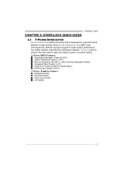
Based on many precise tests, Biostar Engineering Team (BET) has developed this ultimate overclock engine to users' overclock setting. T-Power BIOS Features: Overclocking Navigator Engine (O.N.E.) CMOS Reloading Program (C.R.P.) Memory Integration Test (M.I.T., under Overclock Navigator Engine) Integrated Flash Program (I.F.P.) Smart Fan Function (under ... Engine Smart Fan Function Life Update 25 TA690G AM2 CHAPTER 5: OVERCLOCK QUICK GUIDE 5.1 T-POWER INTRODUCTION Biostar T-Power is a whole new utility that is able to present the best system state according to raise system performance.
Based on many precise tests, Biostar Engineering Team (BET) has developed this ultimate overclock engine to users' overclock setting. T-Power BIOS Features: Overclocking Navigator Engine (O.N.E.) CMOS Reloading Program (C.R.P.) Memory Integration Test (M.I.T., under Overclock Navigator Engine) Integrated Flash Program (I.F.P.) Smart Fan Function (under ... Engine Smart Fan Function Life Update 25 TA690G AM2 CHAPTER 5: OVERCLOCK QUICK GUIDE 5.1 T-POWER INTRODUCTION Biostar T-Power is a whole new utility that is able to present the best system state according to raise system performance.
Setup Manual
Page 27
With an x1 (200MHz) interval. Memclock Frequency: To get better system performance, sometimes downgrading the memory frequency is necessary when CPU frequency is decided by different CPU type. Chipset Overclock Setting: NB/SB Voltage Regulator: This function will ...overclocking. Choices: This range is from 200 to 1.725V, with an interval of 1MHz. The upper limit is adjusted over the upper limit. Memory Overclock Setting: Memory Voltage: This function will increase CPU stability when overclocking. Choices: The range is from 1.85V to 2.0V, with an interval of 1MHz. Choices...
With an x1 (200MHz) interval. Memclock Frequency: To get better system performance, sometimes downgrading the memory frequency is necessary when CPU frequency is decided by different CPU type. Chipset Overclock Setting: NB/SB Voltage Regulator: This function will ...overclocking. Choices: This range is from 200 to 1.725V, with an interval of 1MHz. The upper limit is adjusted over the upper limit. Memory Overclock Setting: Memory Voltage: This function will increase CPU stability when overclocking. Choices: The range is from 1.85V to 2.0V, with an interval of 1MHz. Choices...

Setup Manual
Page 30
... this item is under this test. MIT allows users to ensure the memory stability. Step 1: The default setting under "Overclocking Navigator Engine" item. Motherboard Manual C. Memory Integration Test (M.I.T.): This function is "Disabled"; Run this test for 5 minutes (minimum) to test memory compatibilities, and no extra devices or software are needed. Step 3: When the...
... this item is under this test. MIT allows users to ensure the memory stability. Step 1: The default setting under "Overclocking Navigator Engine" item. Motherboard Manual C. Memory Integration Test (M.I.T.): This function is "Disabled"; Run this test for 5 minutes (minimum) to test memory compatibilities, and no extra devices or software are needed. Step 3: When the...

Setup Manual
Page 38
... two items for CPU overclocking. AGP/PCI-Express Overclocking Setting: By adjusting can configure VGA card overclocking. Interval: 1MHz. 38 A. Memory Clock Frequency Choices: 100, 133, 200, 266, 333, 400, 533, 667, 800. Interval: 0.1V. And this function helps... to increase VGA card performance. CPU Voltage Range: 0.8V~2.0V. Interval: 1MHz. Interval: 1. B. Memory Voltage Range: 1.8V~2.8V. Range: 100MHz~150MHz. A. CPU Frequency Range: 200MHz~450MHz. Interval: 0.0125V. Motherboard Manual CPU Overclocking Settings: By adjusting...
... two items for CPU overclocking. AGP/PCI-Express Overclocking Setting: By adjusting can configure VGA card overclocking. Interval: 1MHz. 38 A. Memory Clock Frequency Choices: 100, 133, 200, 266, 333, 400, 533, 667, 800. Interval: 0.1V. And this function helps... to increase VGA card performance. CPU Voltage Range: 0.8V~2.0V. Interval: 1MHz. Interval: 1. B. Memory Voltage Range: 1.8V~2.8V. Range: 100MHz~150MHz. A. CPU Frequency Range: 200MHz~450MHz. Interval: 0.0125V. Motherboard Manual CPU Overclocking Settings: By adjusting...

Setup Manual
Page 44
...is invaded by two short Video card not found or video card beeps memory bad High-low siren sound CPU overheated System will work properly. 44 Confirm motherboard model and download the respectively BIOS from the Biostar website: www.biostar.com.tw 3. Type "Awdflash xxxx.bf/sn/py/r" in DOS ... error found during POST Long beeps every other second No DRAM detected or install 6.3 EXTRA INFORMATION A. Download the Flash Utility "AWDFLASH.exe" from Biostar website. 4. BIOS Update After you fail to update BIOS or BIOS is shown after boot-up to restore the BIOS: 1. In this Case,...
...is invaded by two short Video card not found or video card beeps memory bad High-low siren sound CPU overheated System will work properly. 44 Confirm motherboard model and download the respectively BIOS from the Biostar website: www.biostar.com.tw 3. Type "Awdflash xxxx.bf/sn/py/r" in DOS ... error found during POST Long beeps every other second No DRAM detected or install 6.3 EXTRA INFORMATION A. Download the Flash Utility "AWDFLASH.exe" from Biostar website. 4. BIOS Update After you fail to update BIOS or BIOS is shown after boot-up to restore the BIOS: 1. In this Case,...

User Manual
Page 2
... 1: Introduction 1 1.1 Before You Start 1 1.2 Package Checklist 1 1.3 Motherboard Features 2 1.4 Rear Panel Connectors 4 1.5 Motherboard Layout 5 Chapter 2: Hardware Installation 6 2.1 Installing Central Processing Unit (CPU 6 2.2 FAN Headers 8 2.3 Installing System Memory 9 2.4 Connectors and Slots 11 Chapter 3: Headers & Jumpers Setup 13 3.1 How to Setup Jumpers 13 3.2 Detail Settings 13 Chapter 4: RAID Functions 19 4.1 Operation System 19 4.2 Raid...
... 1: Introduction 1 1.1 Before You Start 1 1.2 Package Checklist 1 1.3 Motherboard Features 2 1.4 Rear Panel Connectors 4 1.5 Motherboard Layout 5 Chapter 2: Hardware Installation 6 2.1 Installing Central Processing Unit (CPU 6 2.2 FAN Headers 8 2.3 Installing System Memory 9 2.4 Connectors and Slots 11 Chapter 3: Headers & Jumpers Setup 13 3.1 How to Setup Jumpers 13 3.2 Detail Settings 13 Chapter 4: RAID Functions 19 4.1 Operation System 19 4.2 Raid...

User Manual
Page 4
...initiatives H/W Monitor H/W Monitor ITE's "Smart Guardian" function ITE's "Smart Guardian" function DDR2 DIMM Slots x 4 DDR2 DIMM Slots x 4 Max Memory Capacity 4GB Max Memory Capacity 4GB Main Memory Each DIMM supports 256/512MB & 1GB DDR2 Each DIMM supports 256/512MB & 1GB DDR2 Dual Channel Mode DDR2...Registered DIMM and ECC DIMM is not supported supported Graphics Integrated in AMD 690G Chipset Max Shared Video Memory is 512MB Integrated in AMD 690G Chipset Max Shared Video Memory is 512MB Integrated IDE Controller Integrated IDE Controller IDE Ultra DMA 33 / 66 / 100 / 133...
...initiatives H/W Monitor H/W Monitor ITE's "Smart Guardian" function ITE's "Smart Guardian" function DDR2 DIMM Slots x 4 DDR2 DIMM Slots x 4 Max Memory Capacity 4GB Max Memory Capacity 4GB Main Memory Each DIMM supports 256/512MB & 1GB DDR2 Each DIMM supports 256/512MB & 1GB DDR2 Dual Channel Mode DDR2...Registered DIMM and ECC DIMM is not supported supported Graphics Integrated in AMD 690G Chipset Max Shared Video Memory is 512MB Integrated in AMD 690G Chipset Max Shared Video Memory is 512MB Integrated IDE Controller Integrated IDE Controller IDE Ultra DMA 33 / 66 / 100 / 133...

User Manual
Page 11
Memory Modules A690G-M2 DIMMA1 DIMMB1 DIMMA2 DIMMB2 1. Unlock a DIMM slot by pressing the retaining clips outward. 2.3 INSTALLING SYSTEM MEMORY A. Align a DIMM on the slot such that the notch on the DIMM matches the break on the Slot. 2. Insert the DIMM vertically and firmly into the slot until the retaining chip snap back in place and the DIMM is properly seated. 9
Memory Modules A690G-M2 DIMMA1 DIMMB1 DIMMA2 DIMMB2 1. Unlock a DIMM slot by pressing the retaining clips outward. 2.3 INSTALLING SYSTEM MEMORY A. Align a DIMM on the slot such that the notch on the DIMM matches the break on the Slot. 2. Insert the DIMM vertically and firmly into the slot until the retaining chip snap back in place and the DIMM is properly seated. 9

User Manual
Page 12
...To trigger the Dual Channel function of the motherboard, the memory module must meet the following requirements: Install memory module of the memory module must be the same (x8 or x16) 10 Memory Capacity DIMM Socket Location DDR2 Module DIMMA1 256MB/512MB/1024MB ...256MB/512MB/1024MB DIMMA2 256MB/512MB/1024MB DIMMB2 256MB/512MB/1024MB Total Memory Size Max is 4GB. Dual Channel Status DIMMA1 DIMMB1 DIMMA2 DIMMB2 Enabled O O X X Enabled X X O O Enabled O O O O (O means memory installed, X means memory not installed.) The DRAM bus width of the same density in ...
...To trigger the Dual Channel function of the motherboard, the memory module must meet the following requirements: Install memory module of the memory module must be the same (x8 or x16) 10 Memory Capacity DIMM Socket Location DDR2 Module DIMMA1 256MB/512MB/1024MB ...256MB/512MB/1024MB DIMMA2 256MB/512MB/1024MB DIMMB2 256MB/512MB/1024MB Total Memory Size Max is 4GB. Dual Channel Status DIMMA1 DIMMB1 DIMMA2 DIMMB2 Enabled O O X X Enabled X X O O Enabled O O O O (O means memory installed, X means memory not installed.) The DRAM bus width of the same density in ...

User Manual
Page 25
... motherboard model and download the respectively BIOS from the Biostar website: www.biostar.com.tw 3. Type "Awdflash xxxx.bf/sn/py/r" in DOS prompt. (xxxx means BIOS name.) 8. The BIOS has been recovered and will update BIOS automatically and restart. 9. A690G-M2 5.2 AWARD BIOS BEEP CODE Beep Sound Meaning One long... beep followed by virus, the Boot-Block function will help to restore BIOS. BIOS Update After you fail to update BIOS or BIOS is shown after boot-up No error found or video card beeps memory bad High...
... motherboard model and download the respectively BIOS from the Biostar website: www.biostar.com.tw 3. Type "Awdflash xxxx.bf/sn/py/r" in DOS prompt. (xxxx means BIOS name.) 8. The BIOS has been recovered and will update BIOS automatically and restart. 9. A690G-M2 5.2 AWARD BIOS BEEP CODE Beep Sound Meaning One long... beep followed by virus, the Boot-Block function will help to restore BIOS. BIOS Update After you fail to update BIOS or BIOS is shown after boot-up No error found or video card beeps memory bad High...

User Manual
Page 28
... with the CPU speed are synchronically shown on the other hand, helps to install DirectX 8.1.) 26 In addition, the frequency status of CPU, memory, VGA and PCI along with just one . 6.2 SYSTEM REQUIREMENT OS Support: Windows 98 SE, Windows Me, Windows 2000, Windows XP, Windows...a speed that is not appropriate when testing and results in the About panel, you do not need to power up CPU core voltage and Memory voltage. Motherboard Manual CHAPTER 6: WARPSPEEDER™ III 6.1 INTRODUCTION [WarpSpeeder™ III], a new powerful control utility, features three user-friendly ...
... with the CPU speed are synchronically shown on the other hand, helps to install DirectX 8.1.) 26 In addition, the frequency status of CPU, memory, VGA and PCI along with just one . 6.2 SYSTEM REQUIREMENT OS Support: Windows 98 SE, Windows Me, Windows 2000, Windows XP, Windows...a speed that is not appropriate when testing and results in the About panel, you do not need to power up CPU core voltage and Memory voltage. Motherboard Manual CHAPTER 6: WARPSPEEDER™ III 6.1 INTRODUCTION [WarpSpeeder™ III], a new powerful control utility, features three user-friendly ...

User Manual
Page 30
...; III] will appear on the desktop, just like the icon shown below. b. Main Panel contains features as follows: a. Display the CPU Speed, CPU external clock, Memory clock, VGA clock, and PCI clock information. Motherboard Manual 6.4 WARPSPEEDER™ III 1. the utility's first window you can launch the [WarpSpeeder™ III] utility simply...
...; III] will appear on the desktop, just like the icon shown below. b. Main Panel contains features as follows: a. Display the CPU Speed, CPU external clock, Memory clock, VGA clock, and PCI clock information. Motherboard Manual 6.4 WARPSPEEDER™ III 1. the utility's first window you can launch the [WarpSpeeder™ III] utility simply...

User Manual
Page 33
..."+" to increase or "-" to decrease the CPU voltage. A690G-M2 Overvoltage Panel contains these features: a. In this panel, you can get the real-time status information of your system. b. Click on "+" to increase or "-" to decrease the Memory voltage. 4. The information will show up as the following ...figure. "CPU Voltage": This function allows user to adjust Memory voltage. Hardware Monitor Panel Click the Hardware Monitor button in Main Panel, the...
..."+" to increase or "-" to decrease the CPU voltage. A690G-M2 Overvoltage Panel contains these features: a. In this panel, you can get the real-time status information of your system. b. Click on "+" to increase or "-" to decrease the Memory voltage. 4. The information will show up as the following ...figure. "CPU Voltage": This function allows user to adjust Memory voltage. Hardware Monitor Panel Click the Hardware Monitor button in Main Panel, the...


