
User Guide
Page 1
Motherboard Z97-K/USB 3.1
Motherboard Z97-K/USB 3.1

User Guide
Page 3
Contents Safety information iv About this guide iv Package contents vi Z97-K/USB 3.1 specifications summary vi Chapter 1: Product introduction 1.1 Before you proceed 1-1 1.2 Motherboard overview 1-2 1.3 Central Processing Unit (CPU 1-4 1.4 System memory 1-7 1.5 Expansion slots 1-10 1.6 Jumpers 1-12 1.7 Connectors 1-13 1.8 Software ... 2.4 Main menu 2-17 2.5 Ai Tweaker menu 2-19 2.6 Advanced menu 2-31 2.7 Monitor menu 2-41 2.8 Boot menu 2-45 2.9 Tool menu 2-51 2.10 Exit menu 2-52 Appendices Notices...A-1 ASUS contact information A-4 iii
Contents Safety information iv About this guide iv Package contents vi Z97-K/USB 3.1 specifications summary vi Chapter 1: Product introduction 1.1 Before you proceed 1-1 1.2 Motherboard overview 1-2 1.3 Central Processing Unit (CPU 1-4 1.4 System memory 1-7 1.5 Expansion slots 1-10 1.6 Jumpers 1-12 1.7 Connectors 1-13 1.8 Software ... 2.4 Main menu 2-17 2.5 Ai Tweaker menu 2-19 2.6 Advanced menu 2-31 2.7 Monitor menu 2-41 2.8 Boot menu 2-45 2.9 Tool menu 2-51 2.10 Exit menu 2-52 Appendices Notices...A-1 ASUS contact information A-4 iii

User Guide
Page 6
Please refer to Memory QVL (Qualified Vendors List) for details. ** Refer to www.asus.com for Intel® CPU support list. Package contents Check your retailer. Z97-K/USB 3.1 specifications summary CPU Chipset Memory Expansion slots LGA1150 socket for the 4th Generation, ...characteristics of the above items is damaged or missing, contact your motherboard package for the following items. Motherboard Cables Accessories Application DVD Documentation ASUS Z97-K/USB 3.1 motherboard 2 x Serial ATA 6.0 Gb/s cables 1 x I/O Shield Support DVD User Guide If any of individual CPUs. C.)*/2200...
Please refer to Memory QVL (Qualified Vendors List) for details. ** Refer to www.asus.com for Intel® CPU support list. Package contents Check your retailer. Z97-K/USB 3.1 specifications summary CPU Chipset Memory Expansion slots LGA1150 socket for the 4th Generation, ...characteristics of the above items is damaged or missing, contact your motherboard package for the following items. Motherboard Cables Accessories Application DVD Documentation ASUS Z97-K/USB 3.1 motherboard 2 x Serial ATA 6.0 Gb/s cables 1 x I/O Shield Support DVD User Guide If any of individual CPUs. C.)*/2200...

User Guide
Page 7
...-up to three displays simultaneously Maximum shared memory 512MB Intel® Z97 Express Chipset with HD audio module in the front panel to support an 8-channel audio output Intel® Z97 Express Chipset - Intel® HD Graphics support Multi-VGA output... ASUS USB 3.1 Boost - 2 x USB 3.1/3.0/2.0 ports (2 ports at the back panel, teal blue) - 4 x USB 3.0/2.0 ports (2 ports at midboard, 2 ports at the back panel, blue) - 7 x USB 2.0/1.1 ports (6 ports at midboard, 1 port at the back panel) (continued on the CPU installed. Z97-K/USB 3.1 specifications summary Graphics Storage LAN Audio USB ...
...-up to three displays simultaneously Maximum shared memory 512MB Intel® Z97 Express Chipset with HD audio module in the front panel to support an 8-channel audio output Intel® Z97 Express Chipset - Intel® HD Graphics support Multi-VGA output... ASUS USB 3.1 Boost - 2 x USB 3.1/3.0/2.0 ports (2 ports at the back panel, teal blue) - 4 x USB 3.0/2.0 ports (2 ports at midboard, 2 ports at the back panel, blue) - 7 x USB 2.0/1.1 ports (6 ports at midboard, 1 port at the back panel) (continued on the CPU installed. Z97-K/USB 3.1 specifications summary Graphics Storage LAN Audio USB ...

User Guide
Page 8
... protection - Pipe music or movies from your PC status with fast response time M.2 onboard - Ai Charger+ - ASUS Q-Slot (continued on the next page) viii Z97-K/USB 3.1 specifications summary ASUS special features High Performance ASUS 5X PROTECTION - ASUS ESD Guards - ASUS Stainless Steel Back I/O - 3x more durable corrosion-resistant coatin UEFI BIOS - GPU Boost - Disk Unlocker EZ DIY...
... protection - Pipe music or movies from your PC status with fast response time M.2 onboard - Ai Charger+ - ASUS Q-Slot (continued on the next page) viii Z97-K/USB 3.1 specifications summary ASUS special features High Performance ASUS 5X PROTECTION - ASUS ESD Guards - ASUS Stainless Steel Back I/O - 3x more durable corrosion-resistant coatin UEFI BIOS - GPU Boost - Disk Unlocker EZ DIY...

User Guide
Page 9
vCore: Adjustable CPU Core voltage at 0.1MHz increment Overclocking Protection - Z97-K/USB 3.1 specifications summary ASUS quiet thermal solution ASUS exclusive overclocking features Rear panel I /O ports 1 x 19-pin USB 3.0/2.0 connector supports additional 2 USB ports 3 x USB 2.0/1.1 connectors support additional 6 USB ports 1 x M.2 Socket 3 (for M Key, type 2242/2260/2280 devices) 6 x SATA 6.0 Gb/s connectors (gray) 1 x 4-pin CPU Fan connector (PWM mode) 2 x 4-pin Chassis...
vCore: Adjustable CPU Core voltage at 0.1MHz increment Overclocking Protection - Z97-K/USB 3.1 specifications summary ASUS quiet thermal solution ASUS exclusive overclocking features Rear panel I /O ports 1 x 19-pin USB 3.0/2.0 connector supports additional 2 USB ports 3 x USB 2.0/1.1 connectors support additional 6 USB ports 1 x M.2 Socket 3 (for M Key, type 2242/2260/2280 devices) 6 x SATA 6.0 Gb/s connectors (gray) 1 x 4-pin CPU Fan connector (PWM mode) 2 x 4-pin Chassis...

User Guide
Page 10
x 8.6 in . Z97-K/USB 3.1 specifications summary BIOS features Manageability Support DVD OS support Form factor 64 Mb Flash ROM, UEFI AMI BIOS, PnP, DMI 2.7, WfM 2.0, SM BIOS 2.8.0, ACPI 5.0, Multi-language BIOS, ASUS EZ Flash 2, CrashFree BIOS 3, F11 EZ Tuning Wizard, F6 Qfan Control, F3 My ...Favorites, Quick Note, Last Modified Log, F12 PrintScreen function, F3 Shortcut function, and ASUS DRAM SPD (Serial Presence Detect) memory information WfM 2.0, DMI 2.7, WOR by PME, PXE Drivers ASUS utilities EZ Update Anti-virus software (OEM version) Windows® 8.1 Windows® 8 Windows...
x 8.6 in . Z97-K/USB 3.1 specifications summary BIOS features Manageability Support DVD OS support Form factor 64 Mb Flash ROM, UEFI AMI BIOS, PnP, DMI 2.7, WfM 2.0, SM BIOS 2.8.0, ACPI 5.0, Multi-language BIOS, ASUS EZ Flash 2, CrashFree BIOS 3, F11 EZ Tuning Wizard, F6 Qfan Control, F3 My ...Favorites, Quick Note, Last Modified Log, F12 PrintScreen function, F3 Shortcut function, and ASUS DRAM SPD (Serial Presence Detect) memory information WfM 2.0, DMI 2.7, WOR by PME, PXE Drivers ASUS utilities EZ Update Anti-virus software (OEM version) Windows® 8.1 Windows® 8 Windows...

User Guide
Page 11
... you install or remove any component, ensure that the ATX power supply is switched off or the power cord is detached from the power supply. ASUS Z97-K/USB 3.1 1-1
... you install or remove any component, ensure that the ATX power supply is switched off or the power cord is detached from the power supply. ASUS Z97-K/USB 3.1 1-1

User Guide
Page 12
... the chassis in the correct orientation. Unplug the power cord before installing or removing the motherboard. Place this side towards the rear of the chassis Z97-K/USB 3.1 1-2 Chapter 1: Product introduction Do not overtighten the screws! Failure to do so can damage the motherboard.
... the chassis in the correct orientation. Unplug the power cord before installing or removing the motherboard. Place this side towards the rear of the chassis Z97-K/USB 3.1 1-2 Chapter 1: Product introduction Do not overtighten the screws! Failure to do so can damage the motherboard.

User Guide
Page 14
...-6) 7. System panel connector (10-1 pin PANEL) 10. CPU and chassis fan connectors (4-pin CPU_FAN, 4-pin CHA_FAN1/2) 2. USB 3.0 connector (20-1 pin USB3_12) 6. 1.2.4 Layout contents Connectors/Jumpers/Slots/LED 1. USB 2.0 connectors (10-1 pin USB910, USB1112, USB1314) 12. Z97-K/USB 3.1 Z97-K/USB 3.1 CPU socket LGA1150 Unplug all power cables before installing the CPU. 1-4 Chapter 1: Product introduction LGA1150 CPU socket 4.
...-6) 7. System panel connector (10-1 pin PANEL) 10. CPU and chassis fan connectors (4-pin CPU_FAN, 4-pin CHA_FAN1/2) 2. USB 3.0 connector (20-1 pin USB3_12) 6. 1.2.4 Layout contents Connectors/Jumpers/Slots/LED 1. USB 2.0 connectors (10-1 pin USB910, USB1112, USB1314) 12. Z97-K/USB 3.1 Z97-K/USB 3.1 CPU socket LGA1150 Unplug all power cables before installing the CPU. 1-4 Chapter 1: Product introduction LGA1150 CPU socket 4.

User Guide
Page 15
...purchase of the PnP cap. 1.3.1 Installing the CPU 1 A B 2 3 ASUS Z97-K/USB 3.1 1-5 Contact your retailer immediately if the PnP cap is missing, or if...ensure that the PnP cap is shipment/ transit-related. • Keep the cap after installing the motherboard. ASUS will shoulder the cost of repair only if the damage is on the LGA1150 socket. • The ...product warranty does not cover damage to the PnP cap/socket contacts/motherboard components. ASUS will process Return Merchandise Authorization (RMA) requests only if the motherboard comes with the cap on the ...
...purchase of the PnP cap. 1.3.1 Installing the CPU 1 A B 2 3 ASUS Z97-K/USB 3.1 1-5 Contact your retailer immediately if the PnP cap is missing, or if...ensure that the PnP cap is shipment/ transit-related. • Keep the cap after installing the motherboard. ASUS will shoulder the cost of repair only if the damage is on the LGA1150 socket. • The ...product warranty does not cover damage to the PnP cap/socket contacts/motherboard components. ASUS will process Return Merchandise Authorization (RMA) requests only if the motherboard comes with the cap on the ...

User Guide
Page 17
The figure illustrates the location of the DDR3 DIMM sockets: DIMM_A1 DIMM_A2 DIMM_B1 DIMM_B2 Z97-K/USB 3.1 Channel Channel A Channel B Sockets DIMM_A1 and DIMM_A2 DIMM_B1 and DIMM_B2 Z97-K/USB 3.1 240-pin DDR3 DIMM sockets ASUS Z97-K/USB 3.1 1-7 3 4 To uninstall the CPU heatsink and fan assembly 1 2 A B B A 1.4 System memory 1.4.1 Overview This motherboard comes with four Double Data Rate 3 (DDR3) Dual Inline Memory Module (DIMM) sockets.
The figure illustrates the location of the DDR3 DIMM sockets: DIMM_A1 DIMM_A2 DIMM_B1 DIMM_B2 Z97-K/USB 3.1 Channel Channel A Channel B Sockets DIMM_A1 and DIMM_A2 DIMM_B1 and DIMM_B2 Z97-K/USB 3.1 240-pin DDR3 DIMM sockets ASUS Z97-K/USB 3.1 1-7 3 4 To uninstall the CPU heatsink and fan assembly 1 2 A B B A 1.4 System memory 1.4.1 Overview This motherboard comes with four Double Data Rate 3 (DDR3) Dual Inline Memory Module (DIMM) sockets.

User Guide
Page 19
1.4.3 Installing a DIMM To install a DIMM 1 2 3 To remove a DIMM B A A ASUS Z97-K/USB 3.1 1-9
1.4.3 Installing a DIMM To install a DIMM 1 2 3 To remove a DIMM B A A ASUS Z97-K/USB 3.1 1-9
User Guide
Page 21
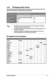
... Express 3.0/2.0 x16 slot that you provide sufficient power when using multiple graphics cards for better thermal environment. shared - - - - - - shared - - - - - - - - See page 1-19 for this motherboard I.G.D. ASUS Z97-K/USB 3.1 1-11
... Express 3.0/2.0 x16 slot that you provide sufficient power when using multiple graphics cards for better thermal environment. shared - - - - - - shared - - - - - - - - See page 1-19 for this motherboard I.G.D. ASUS Z97-K/USB 3.1 1-11

User Guide
Page 22
... (3-pin CLRTC) This jumper allows you to clear the Real Time Clock (RTC) RAM in CMOS, which include system setup information such as system passwords. Z97-K/USB 3.1 CLRTC 12 23 Normal (Default) Clear RTC Z97-K/USB 3.1 Clear RTC RAM To erase the RTC RAM: 1. Keep the cap on CLRTC jumper default position.
... (3-pin CLRTC) This jumper allows you to clear the Real Time Clock (RTC) RAM in CMOS, which include system setup information such as system passwords. Z97-K/USB 3.1 CLRTC 12 23 Normal (Default) Clear RTC Z97-K/USB 3.1 Clear RTC RAM To erase the RTC RAM: 1. Keep the cap on CLRTC jumper default position.

User Guide
Page 23
... the tape, CD, DVD player, or other VGA-compatible devices. 3. In the 4.1, 5.1, and 7.1-channel configurations, the function of the audio ports in 2.1, 4.1, 5.1, or 7.1-channel configuration. ASUS Z97-K/USB 3.1 1-13 LAN (RJ-45) port. This port connects to the audio configuration table on the next page for a PS/2 mouse. 2. 1.7 1.7.1 1 Connectors Rear panel connectors 2 3 45...
... the tape, CD, DVD player, or other VGA-compatible devices. 3. In the 4.1, 5.1, and 7.1-channel configurations, the function of the audio ports in 2.1, 4.1, 5.1, or 7.1-channel configuration. ASUS Z97-K/USB 3.1 1-13 LAN (RJ-45) port. This port connects to the audio configuration table on the next page for a PS/2 mouse. 2. 1.7 1.7.1 1 Connectors Rear panel connectors 2 3 45...

User Guide
Page 25
... CHA_FAN2 A CPU FAN PWM CPU FAN IN CPU FAN PWR GND +5V CHA FAN IN CHA FAN PWR GND Z97-K/USB 3.1 B C C CHA_FAN1 +5V CHA FAN IN CHA FAN PWR GND Z97-K/USB 3.1 Fan connectors • DO NOT forget to connect the fan cables to the CPU fan connector. Insufficient air flow... system may damage the motherboard components. COM PIN 1 RXD DTR DSR CTS DCD TXD GND RTS RI Z97-K/USB 3.1 Z97-K/USB 3.1 Serial port (COM) connector The COM module is for a serial (COM) port. ASUS Z97-K/USB 3.1 1-15 These are not jumpers! Connect the serial port module cable to this connector, then install...
... CHA_FAN2 A CPU FAN PWM CPU FAN IN CPU FAN PWR GND +5V CHA FAN IN CHA FAN PWR GND Z97-K/USB 3.1 B C C CHA_FAN1 +5V CHA FAN IN CHA FAN PWR GND Z97-K/USB 3.1 Fan connectors • DO NOT forget to connect the fan cables to the CPU fan connector. Insufficient air flow... system may damage the motherboard components. COM PIN 1 RXD DTR DSR CTS DCD TXD GND RTS RI Z97-K/USB 3.1 Z97-K/USB 3.1 Serial port (COM) connector The COM module is for a serial (COM) port. ASUS Z97-K/USB 3.1 1-15 These are not jumpers! Connect the serial port module cable to this connector, then install...

User Guide
Page 26
... 1 PIN 1 MIC2 MICPWR Line out_R NC Line out_L PORT1 L PORT1 R PORT2 R SENSE_SEND PORT2 L Z97-K/USB 3.1 HD-audio-compliant Legacy AC'97 pin definition compliant definition Z97-K/USB 3.1 Front panel audio connector • We recommend that you connect a high-definition front panel audio module... to this connector to avail of maximum 1A (12 W) fan power. • The CPU_FAN and CHA_FAN connectors support the ASUS FAN Xpert 2+ ...
... 1 PIN 1 MIC2 MICPWR Line out_R NC Line out_L PORT1 L PORT1 R PORT2 R SENSE_SEND PORT2 L Z97-K/USB 3.1 HD-audio-compliant Legacy AC'97 pin definition compliant definition Z97-K/USB 3.1 Front panel audio connector • We recommend that you connect a high-definition front panel audio module... to this connector to avail of maximum 1A (12 W) fan power. • The CPU_FAN and CHA_FAN connectors support the ASUS FAN Xpert 2+ ...

User Guide
Page 27
...]. See section 2.6.3 PCH Storage Configuration for more details. M.2 Socket 3 shares the bandwidth with the Intel® Rapid Storage Technology through the onboard Intel® Z97 chipset. ASUS Z97-K/USB 3.1 1-17 SATA6G_1 GND RSATA_TXP1 RSATA_TXN1 GND RSATA_RXP1 RSATA_RXN1 GND SATA6G_2 GND RSATA_TXP2 RSATA_TXN2 GND RSATA_RXP2 RSATA_RXN2 GND SATA6G_6 SATA6G_5 GND RSATA_TXP6 RSATA_TXN6 GND RSATA_RXN6 RSATA_RXP6...
...]. See section 2.6.3 PCH Storage Configuration for more details. M.2 Socket 3 shares the bandwidth with the Intel® Rapid Storage Technology through the onboard Intel® Z97 chipset. ASUS Z97-K/USB 3.1 1-17 SATA6G_1 GND RSATA_TXP1 RSATA_TXN1 GND RSATA_RXP1 RSATA_RXN1 GND SATA6G_2 GND RSATA_TXP2 RSATA_TXN2 GND RSATA_RXP2 RSATA_RXN2 GND SATA6G_6 SATA6G_5 GND RSATA_TXP6 RSATA_TXN6 GND RSATA_RXN6 RSATA_RXP6...

User Guide
Page 28
... connector is purchased separately. 1-18 Chapter 1: Product introduction LPCPD# GND +3VSB NC LAD0 +3V LAD3 PCIRST# LFRAME# LCLK Z97-K/USB 3.1 TPM PIN 1 NC CLKRUN# SERIRQ NC GND LAD1 LAD2 NC GND Z97-K/USB 3.1 TPM connector The TPM module is for an additional Sony/Philips Digital Interface (S/PDIF) port. TPM connector (20-1 pin TPM...PDIF Out module cable to this connector, then install the module to a slot opening at the back of the system chassis. +5V SPDIFOUT GND Z97-K/USB 3.1 PIN 1 SPDIF_OUT Z97-K/USB 3.1 Digital audio connector The S/PDIF module is purchased separately. 6.
... connector is purchased separately. 1-18 Chapter 1: Product introduction LPCPD# GND +3VSB NC LAD0 +3V LAD3 PCIRST# LFRAME# LCLK Z97-K/USB 3.1 TPM PIN 1 NC CLKRUN# SERIRQ NC GND LAD1 LAD2 NC GND Z97-K/USB 3.1 TPM connector The TPM module is for an additional Sony/Philips Digital Interface (S/PDIF) port. TPM connector (20-1 pin TPM...PDIF Out module cable to this connector, then install the module to a slot opening at the back of the system chassis. +5V SPDIFOUT GND Z97-K/USB 3.1 PIN 1 SPDIF_OUT Z97-K/USB 3.1 Digital audio connector The S/PDIF module is purchased separately. 6.


