User Guide
Page 10
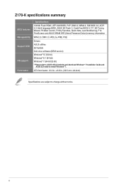
x x 8.8 in . ATX form factor: 12.0 in . (30.5 cm x 22.4cm) Specifications are subject to install Windows® 7. Z170-K specifications summary BIOS features Manageability Support DVD OS support Form factor Specifications 128 Mb Flash ROM, UEFI AMI BIOS, PnP, DMI3.0, WfM2.0, SM BIOS 3.0, ACPI 5.0, Multi-language BIOS, ASUS EZ Flash 3, CrashFree BIOS 3, F11 EZ Tuning...
x x 8.8 in . ATX form factor: 12.0 in . (30.5 cm x 22.4cm) Specifications are subject to install Windows® 7. Z170-K specifications summary BIOS features Manageability Support DVD OS support Form factor Specifications 128 Mb Flash ROM, UEFI AMI BIOS, PnP, DMI3.0, WfM2.0, SM BIOS 3.0, ACPI 5.0, Multi-language BIOS, ASUS EZ Flash 3, CrashFree BIOS 3, F11 EZ Tuning...

User Guide
Page 11
...touching the ICs on them. • Whenever you uninstall any component, place it on a grounded antistatic pad or in the bag that the ATX power supply is switched off or the power cord is detached from the wall socket before installing or removing the motherboard. Failure to do so... the chassis as the power supply case, to avoid damaging them due to static electricity. • Hold components by the edges to the chassis. ASUS Z170-K 1-1 Doing so can cause you install or remove any motherboard settings. • Unplug the power cord from the power supply. Do not overtighten ...
...touching the ICs on them. • Whenever you uninstall any component, place it on a grounded antistatic pad or in the bag that the ATX power supply is switched off or the power cord is detached from the wall socket before installing or removing the motherboard. Failure to do so... the chassis as the power supply case, to avoid damaging them due to static electricity. • Hold components by the edges to the chassis. ASUS Z170-K 1-1 Doing so can cause you install or remove any motherboard settings. • Unplug the power cord from the power supply. Do not overtighten ...

User Guide
Page 13
USB 3.0 connector (20-1 pin USB3_12, USB3_34) 6. Intel® Z170 Serial ATA 6.0 Gb/s connector (7-pin SATA6G_3~6) 10. Clear RTC RAM (2-pin CLRTC) 12. Serial port connectors (10-1 pin COM) 14... CPU socket 4. ATX power connectors (24-pin EATXPWR, 8-pin ATX12V) 2. Standby power LED (SB_PWR) 8. CPU, chassis fan connectors (4-pin CPU_FAN, 4-pin CHA_FAN1~2) 3. DDR4 DIMM slots 5. Intel® Z170 SATAEXPRESS (7-pin SATA 6G_12) 9. Digital audio connector (4-1 pin SPDIF_OUT) 15. System panel connector (20-5 pin PANEL) 11. Z170-K Z170-K CPU socket LGA1151 ASUS Z170-K 1-3 M.2 Socket...
USB 3.0 connector (20-1 pin USB3_12, USB3_34) 6. Intel® Z170 Serial ATA 6.0 Gb/s connector (7-pin SATA6G_3~6) 10. Clear RTC RAM (2-pin CLRTC) 12. Serial port connectors (10-1 pin COM) 14... CPU socket 4. ATX power connectors (24-pin EATXPWR, 8-pin ATX12V) 2. Standby power LED (SB_PWR) 8. CPU, chassis fan connectors (4-pin CPU_FAN, 4-pin CHA_FAN1~2) 3. DDR4 DIMM slots 5. Intel® Z170 SATAEXPRESS (7-pin SATA 6G_12) 9. Digital audio connector (4-1 pin SPDIF_OUT) 15. System panel connector (20-5 pin PANEL) 11. Z170-K Z170-K CPU socket LGA1151 ASUS Z170-K 1-3 M.2 Socket...

User Guide
Page 27
...Power OK -5 Volts GND PIN 1 +5 Volts GND GND GND GND GND GND GND GND +5 Volts PSON# GND GND Z170-K +3 Volts -12 Volts +3 Volts +3 Volts PIN 1 Z170-K ATX power connectors • For a fully configured system, we recommend that you use a PSU with higher power output when configuring ...a system with ATX 12 V Specification 2.0 (or later version) and provides a minimum power of 350 W. • DO NOT forget to the Recommended Power Supply Wattage Calculator at http://support.asus. ASUS Z170-K 1-17 Find the proper orientation and push ...
...Power OK -5 Volts GND PIN 1 +5 Volts GND GND GND GND GND GND GND GND +5 Volts PSON# GND GND Z170-K +3 Volts -12 Volts +3 Volts +3 Volts PIN 1 Z170-K ATX power connectors • For a fully configured system, we recommend that you use a PSU with higher power output when configuring ...a system with ATX 12 V Specification 2.0 (or later version) and provides a minimum power of 350 W. • DO NOT forget to the Recommended Power Supply Wattage Calculator at http://support.asus. ASUS Z170-K 1-17 Find the proper orientation and push ...
User Guide
Page 32
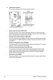
...the chassis-mounted system warning speaker. PWR_SW SPEAKER PLED+ PLEDPWR GND +5V GND GND Speaker HDD_LED+ HDD_LED- RESET +PWR_LED* Requires an ATX power supply Z170-K System panel connector • System power LED (4-pin +PWR_LED-) This 2-pin connector is for system reboot without turning off mode ...or soft-off the system power. 1-22 Chapter 1: Product introduction The HDD LED lights up when you to this connector. PANEL +PWR_LED- Z170-K PIN 1 +HDD_LED- Pressing the power switch for more than four seconds while the system is ON turns the system OFF. • Reset...
...the chassis-mounted system warning speaker. PWR_SW SPEAKER PLED+ PLEDPWR GND +5V GND GND Speaker HDD_LED+ HDD_LED- RESET +PWR_LED* Requires an ATX power supply Z170-K System panel connector • System power LED (4-pin +PWR_LED-) This 2-pin connector is for system reboot without turning off mode ...or soft-off the system power. 1-22 Chapter 1: Product introduction The HDD LED lights up when you to this connector. PANEL +PWR_LED- Z170-K PIN 1 +HDD_LED- Pressing the power switch for more than four seconds while the system is ON turns the system OFF. • Reset...

