
User Guide
Page 3
Contents Safety information...vii About this guide...viii X99-E WS specifications summary x Package contents...xv Installation tools and components xvi Chapter 1: Product Introduction 1.1 Special features... fan assembly installation 2-5 2.1.4 DIMM installation 2-6 2.1.5 ATX Power connection 2-7 2.1.6 SATA device connection 2-8 2.1.7 Front I/O Connector 2-9 2.1.8 Expansion Card installation 2-10 2.2 BIOS update utility 2-11 2.3 Q-Code Logger utility 2-12 2.3.1 Using the Q-Code Logger 2-12 2.4 Motherboard rear and audio connections 2-13 2.4.1 Rear I/O connection 2-13 ...
Contents Safety information...vii About this guide...viii X99-E WS specifications summary x Package contents...xv Installation tools and components xvi Chapter 1: Product Introduction 1.1 Special features... fan assembly installation 2-5 2.1.4 DIMM installation 2-6 2.1.5 ATX Power connection 2-7 2.1.6 SATA device connection 2-8 2.1.7 Front I/O Connector 2-9 2.1.8 Expansion Card installation 2-10 2.2 BIOS update utility 2-11 2.3 Q-Code Logger utility 2-12 2.3.1 Using the Q-Code Logger 2-12 2.4 Motherboard rear and audio connections 2-13 2.4.1 Rear I/O connection 2-13 ...
User Guide
Page 5
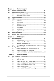
... the support DVD 4-1 4.2.2 Obtaining the software manuals 4-3 4.3 Software information 4-4 4.4 AI Suite 3...4-4 4.4.1 Ai Charger 4-7 4.4.2 USB 3.0 Boost 4-8 4.4.3 EZ Update 4-9 4.4.4 USB BIOS Flashback 4-11 4.4.5 USB Charger 4-13 4.4.6 Push Notice 4-14 4.4.7 System Information 4-17 4.5 Audio configurations 4-18 4.6 ASUS Dr. Power Utility 4-20 Chapter 5: RAID support 5.1 RAID configurations 5-1 5.1.1 RAID definitions 5-1 5.1.2 Installing Serial ATA hard disks 5-2 5.1.3 Setting the...
... the support DVD 4-1 4.2.2 Obtaining the software manuals 4-3 4.3 Software information 4-4 4.4 AI Suite 3...4-4 4.4.1 Ai Charger 4-7 4.4.2 USB 3.0 Boost 4-8 4.4.3 EZ Update 4-9 4.4.4 USB BIOS Flashback 4-11 4.4.5 USB Charger 4-13 4.4.6 Push Notice 4-14 4.4.7 System Information 4-17 4.5 Audio configurations 4-18 4.6 ASUS Dr. Power Utility 4-20 Chapter 5: RAID support 5.1 RAID configurations 5-1 5.1.1 RAID definitions 5-1 5.1.2 Installing Serial ATA hard disks 5-2 5.1.3 Setting the...

User Guide
Page 8
... it supports. Chapter 1: Product introduction This chapter describes the features of the switches, jumpers, and connectors on ASUS hardware and software products. 2. Detailed descriptions of the BIOS parameters are not part of the support DVD that may include optional documentation, such as warranty flyers, that comes...support This chapter describes the contents of the standard package. Where to find more information Refer to change system settings through the BIOS Setup menus. How this guide This user guide contains the information you have been added by your dealer. Chapter...
... it supports. Chapter 1: Product introduction This chapter describes the features of the switches, jumpers, and connectors on ASUS hardware and software products. 2. Detailed descriptions of the BIOS parameters are not part of the support DVD that may include optional documentation, such as warranty flyers, that comes...support This chapter describes the contents of the standard package. Where to find more information Refer to change system settings through the BIOS Setup menus. How this guide This user guide contains the information you have been added by your dealer. Chapter...

User Guide
Page 12
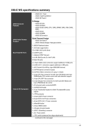
... options with smart devices in real time USB BIOS Flashback - Compatible with lower pings and less lags Crystal Sound 2 - X99-E WS specifications summary ASUS Exclusive Features EPU - EPU, EPU switch ASUS Fan Xpert3 - Featuring Fan Auto Tuning function and multiple thermistors selection for EZ BIOS download scheduling UEFI BIOS EZ Mode - Experience smooth online gaming with the...
... options with smart devices in real time USB BIOS Flashback - Compatible with lower pings and less lags Crystal Sound 2 - X99-E WS specifications summary ASUS Exclusive Features EPU - EPU, EPU switch ASUS Fan Xpert3 - Featuring Fan Auto Tuning function and multiple thermistors selection for EZ BIOS download scheduling UEFI BIOS EZ Mode - Experience smooth online gaming with the...
User Guide
Page 13
...x eSATA ports 1 x Optical S/PDIF Out port 2 x LAN (RJ45) ports (2 x Intel® LAN) 8 Audio I /O Connectors - ASUS Q-Code - ASUS CrashFree BIOS 3 - X99-E WS specifications summary ASUS Exclusive Features ASUS Quiet Thermal Solution Rear Panel I/O Ports Internal I /O jacks 2 x 19-pin USB 3.0/2.0 connectors support additional 4 USB ports 2 x USB 2.0/1.1... 1 x Front panel audio connector(AAFP) 1 x S/PDIF Out header 1 x 5-pin Thunderbolt header for ASUS ThunderboltEX series support 1 x TPM connector 1 x 24-pin EATX Power connector 2 x 8-pin EATX 12V Power connectors 1 x 6-pin EATX ...
...x eSATA ports 1 x Optical S/PDIF Out port 2 x LAN (RJ45) ports (2 x Intel® LAN) 8 Audio I /O Connectors - ASUS Q-Code - ASUS CrashFree BIOS 3 - X99-E WS specifications summary ASUS Exclusive Features ASUS Quiet Thermal Solution Rear Panel I/O Ports Internal I /O jacks 2 x 19-pin USB 3.0/2.0 connectors support additional 4 USB ports 2 x USB 2.0/1.1... 1 x Front panel audio connector(AAFP) 1 x S/PDIF Out header 1 x 5-pin Thunderbolt header for ASUS ThunderboltEX series support 1 x TPM connector 1 x 24-pin EATX Power connector 2 x 8-pin EATX 12V Power connectors 1 x 6-pin EATX ...

User Guide
Page 14
x 10.5 in . xiv X99-E WS specifications summary Internal I/O Connectors BIOS features Manageability Support DVD Operating system Form Factors 1 x EPU switch 1 x EZ XMP switch 1 x Power-on button 1 x Reset button 1 x 3-pin Chassis intrusion (CHASSIS) connector System Panel (Q-Connector) 128 Mb Flash ROM, UEFI AMI BIOS, PnP, DMI 2.7, WfM 2.0, SM BIOS 2.7, ACPI 5.0, Multi-language BIOS, ASUS EZ Flash 2, CrashFree BIOS 3, F11 EZ...
x 10.5 in . xiv X99-E WS specifications summary Internal I/O Connectors BIOS features Manageability Support DVD Operating system Form Factors 1 x EPU switch 1 x EZ XMP switch 1 x Power-on button 1 x Reset button 1 x 3-pin Chassis intrusion (CHASSIS) connector System Panel (Q-Connector) 128 Mb Flash ROM, UEFI AMI BIOS, PnP, DMI 2.7, WfM 2.0, SM BIOS 2.7, ACPI 5.0, Multi-language BIOS, ASUS EZ Flash 2, CrashFree BIOS 3, F11 EZ...
User Guide
Page 24
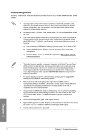
...motherboard. The stability and compatibility of the lower-sized channel for overclocking may install varying memory sizes in the BIOS for the hyper DIMM support. • Visit the ASUS website for the latest QVL. or D.O.C.P. Any excess memory from the higher-sized channel is then mapped ...for single-channel operation. • According to get the correct memory modules. • ASUS exclusively provides hyper DIMM support function. • Hyper DIMM support is the standard way of individual CPUs. com/kb/929605/en-us. •...
...motherboard. The stability and compatibility of the lower-sized channel for overclocking may install varying memory sizes in the BIOS for the hyper DIMM support. • Visit the ASUS website for the latest QVL. or D.O.C.P. Any excess memory from the higher-sized channel is then mapped ...for single-channel operation. • According to get the correct memory modules. • ASUS exclusively provides hyper DIMM support function. • Hyper DIMM support is the standard way of individual CPUs. com/kb/929605/en-us. •...
User Guide
Page 29
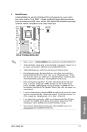
... and update to its default settings. • We recommend that the BIOS has been restored to the latest BIOS version from www.asus.com after using the MemOK! Press and hold the MemOK! function. ASUS X99-E WS 1-13 Chapter 1 button lights continuously. If the test fails, the system... reboots and test the next set is not properly installed. If the installed DIMMs still fail to boot and load the BIOS default settings. function. • The...
... and update to its default settings. • We recommend that the BIOS has been restored to the latest BIOS version from www.asus.com after using the MemOK! Press and hold the MemOK! function. ASUS X99-E WS 1-13 Chapter 1 button lights continuously. If the test fails, the system... reboots and test the next set is not properly installed. If the installed DIMMs still fail to boot and load the BIOS default settings. function. • The...

User Guide
Page 30
... will be activated after the next system bootup. • You may use the 5-Way Optimization and TPU feature in the AI Suite 3 application, adjust the BIOS setup program or enable the TPU switch at the same time. 4. Chapter 1 • The TPU LEDs (TPU_LED) near the TPU switch light up when you...
... will be activated after the next system bootup. • You may use the 5-Way Optimization and TPU feature in the AI Suite 3 application, adjust the BIOS setup program or enable the TPU switch at the same time. 4. Chapter 1 • The TPU LEDs (TPU_LED) near the TPU switch light up when you...

User Guide
Page 31
... is powered off. • The EPU LED (O2LED3) near the EPU switch lights up when you enable the EPU switch. 5. Chapter 1 ASUS X99-E WS 1-15 Refer to automatically detect the current PC loadings and intelligently moderate the power consumption. However, the system will use the last setting you enable... the EPU function will be activated after the next system bootup. • You may change the EPU settings in the software application or BIOS setup program and enable the EPU function at the same time. Enable this switch to section 1.2.8 Onboard LEDs for the exact location of the...
... is powered off. • The EPU LED (O2LED3) near the EPU switch lights up when you enable the EPU switch. 5. Chapter 1 ASUS X99-E WS 1-15 Refer to automatically detect the current PC loadings and intelligently moderate the power consumption. However, the system will use the last setting you enable... the EPU function will be activated after the next system bootup. • You may change the EPU settings in the software application or BIOS setup program and enable the EPU function at the same time. Enable this switch to section 1.2.8 Onboard LEDs for the exact location of the...

User Guide
Page 32
.... Power Utility then enable this button to clear the BIOS setup information only when the systems hangs due to display notification messages in your Windows screen if a problem is detected with your Power Supply Unit (PSU). Refer to enable or disable the ASUS Dr. Power feature. Dr. Power switch (DR_POWER) This switch...
.... Power Utility then enable this button to clear the BIOS setup information only when the systems hangs due to display notification messages in your Windows screen if a problem is detected with your Power Supply Unit (PSU). Refer to enable or disable the ASUS Dr. Power feature. Dr. Power switch (DR_POWER) This switch...

User Guide
Page 34
... of the chassis fans. Set pins 2-3 to switch fan pin selection. Chassis Fan control setting jumper (3-pin CHAFAN_SEL) These jumpers allow you to let the BIOS control the settings of the 4-pin PWM fans.
... of the chassis fans. Set pins 2-3 to switch fan pin selection. Chassis Fan control setting jumper (3-pin CHAFAN_SEL) These jumpers allow you to let the BIOS control the settings of the 4-pin PWM fans.

User Guide
Page 43
...; X99 Serial ATA 6 Gb/s connectors (7-pin SATA6G_12, SATA6G_34, SATA6G_56/SATAEXPRESS_1, SATA6G_78, SATA6G_910) These connectors connect to [AHCI Mode] by default. Refer to section 3.6.3 PCH Storage Configuration for details. • Before creating a RAID set, refer to the manual bundled in the BIOS to...configuration with the Intel® Rapid Storage Technology through the onboard Intel® X99 chipset. If you can support one SATA Express device or two SATA devices. • Due to [RAID Mode]. ASUS X99-E WS 1-27 If you installed Serial ATA hard disk drives, you intend to ...
...; X99 Serial ATA 6 Gb/s connectors (7-pin SATA6G_12, SATA6G_34, SATA6G_56/SATAEXPRESS_1, SATA6G_78, SATA6G_910) These connectors connect to [AHCI Mode] by default. Refer to section 3.6.3 PCH Storage Configuration for details. • Before creating a RAID set, refer to the manual bundled in the BIOS to...configuration with the Intel® Rapid Storage Technology through the onboard Intel® X99 chipset. If you can support one SATA Express device or two SATA devices. • Due to [RAID Mode]. ASUS X99-E WS 1-27 If you installed Serial ATA hard disk drives, you intend to ...

User Guide
Page 44
... you want to connect a high-definition or an AC'97 front panel audio module to this connector, set the Front Panel Type item in the BIOS setup to this connector. Chapter 1 • We recommend that supports either HD Audio or legacy AC`97 audio standard. 4. Connect one end of the front...
... you want to connect a high-definition or an AC'97 front panel audio module to this connector, set the Front Panel Type item in the BIOS setup to this connector. Chapter 1 • We recommend that supports either HD Audio or legacy AC`97 audio standard. 4. Connect one end of the front...

User Guide
Page 47
..., CPU optional, and chassis fan connectors (4-pin CPU_FAN; 4-pin CPU_OPT; 4-pin CHA_FAN1-4) Connect the fan cables to the fan connectors on X99 platform. • The CPU fan connector detects the type of CPU fan installed and automatically switches the control modes. Chapter 1 •... the motherboard, ensuring that the CPU fan cable is securely installed to the fan connectors. ASUS X99-E WS 1-31 To configure the CPU fan's control mode, go to Advanced Mode > Monitor > CPU Q-Fan Control item in BIOS. To set these fans to DC or PWM, go to Advanced Mode > Monitor > ...
..., CPU optional, and chassis fan connectors (4-pin CPU_FAN; 4-pin CPU_OPT; 4-pin CHA_FAN1-4) Connect the fan cables to the fan connectors on X99 platform. • The CPU fan connector detects the type of CPU fan installed and automatically switches the control modes. Chapter 1 •... the motherboard, ensuring that the CPU fan cable is securely installed to the fan connectors. ASUS X99-E WS 1-31 To configure the CPU fan's control mode, go to Advanced Mode > Monitor > CPU Q-Fan Control item in BIOS. To set these fans to DC or PWM, go to Advanced Mode > Monitor > ...

User Guide
Page 52
... labeled "Chassis Signal" and "Ground" are shorted with a jumper cap. Chapter 1 1-36 Chapter 1: Product introduction Remove the jumper caps and enable the related options in BIOS if you reconnect the sensor or switch to this connector when a chassis component is removed or replaced. 15. The chassis intrusion sensor or switch sends...
... labeled "Chassis Signal" and "Ground" are shorted with a jumper cap. Chapter 1 1-36 Chapter 1: Product introduction Remove the jumper caps and enable the related options in BIOS if you reconnect the sensor or switch to this connector when a chassis component is removed or replaced. 15. The chassis intrusion sensor or switch sends...

User Guide
Page 65
... until the light goes out, indicating that supports USB BIOS Flashback. 3. If this means that the BIOS Flashback function is completed. ASUS X99-E WS 2-11 Shut down your local ASUS Service Center. In case of the USB port that the BIOS updating process is enabled. Launch the USB BIOS Flashback Wizard to the optical drive and install the...
... until the light goes out, indicating that supports USB BIOS Flashback. 3. If this means that the BIOS Flashback function is completed. ASUS X99-E WS 2-11 Shut down your local ASUS Service Center. In case of the USB port that the BIOS updating process is enabled. Launch the USB BIOS Flashback Wizard to the optical drive and install the...

User Guide
Page 67
USB 3.0 ports 12 (Supports USB 3.0 Boost) 5. ASUS X99-E WS 2-13 2.4 Motherboard rear and audio connections 2.4.1 Rear I /O ports*** * and **: Refer to the tables on the next page for the LAN port LEDs... 34 (Support USB 3.0 Boost) 4. Q-Code Logger button 7. USB 3.0 ports E12 (Supports USB 3.0 3.0 Boost, upper port supports Boost) Q-Code Logger, lower port supports USB BIOS Flashback) 3. USB BIOS Flashback 11. eSATA ports 12 12. Audio I /O connection Chapter 2 Rear panel connectors 1. Intel® LAN port (LAN1)* 10. USB 3.0 ports E34 (Supports USB 3.0 Boost...
USB 3.0 ports 12 (Supports USB 3.0 Boost) 5. ASUS X99-E WS 2-13 2.4 Motherboard rear and audio connections 2.4.1 Rear I /O ports*** * and **: Refer to the tables on the next page for the LAN port LEDs... 34 (Support USB 3.0 Boost) 4. Q-Code Logger button 7. USB 3.0 ports E12 (Supports USB 3.0 3.0 Boost, upper port supports Boost) Q-Code Logger, lower port supports USB BIOS Flashback) 3. USB BIOS Flashback 11. eSATA ports 12 12. Audio I /O connection Chapter 2 Rear panel connectors 1. Intel® LAN port (LAN1)* 10. USB 3.0 ports E34 (Supports USB 3.0 Boost...

User Guide
Page 68
...2 2-14 Chapter 2: Basic installation Some legacy USB devices must update their firmware for your USB 3.0 devices. • Due to the design of the Intel® X99 series chipset, all USB devices connected to wake up then steady) from S5 mode ACT/LINK SPEED LED LED LAN port You can disable the... LAN controllers in BIOS. Due to hardware design, the LAN1 port's LEDs may run on xHCI mode or EHCI mode, depending on the operating system's setting. • USB 3.0 ...
...2 2-14 Chapter 2: Basic installation Some legacy USB devices must update their firmware for your USB 3.0 devices. • Due to the design of the Intel® X99 series chipset, all USB devices connected to wake up then steady) from S5 mode ACT/LINK SPEED LED LED LAN port You can disable the... LAN controllers in BIOS. Due to hardware design, the LAN1 port's LEDs may run on xHCI mode or EHCI mode, depending on the operating system's setting. • USB 3.0 ...

User Guide
Page 71
...you do not see anything within 30 seconds from orange to green after the system LED turns on test. Connect the power cord to the BIOS beep codes table) or additional messages appear on the screen. If your retailer for the first time 1. The system then runs the power...are running, the BIOS beeps (refer to the power connector at the back of the system chassis. 4. Connect the power cord to a power outlet that all the connections, replace the system case cover. 2. After applying power, the system power LED on the devices in the following order: a. ASUS X99-E WS 2-17 Chapter 2...
...you do not see anything within 30 seconds from orange to green after the system LED turns on test. Connect the power cord to the BIOS beep codes table) or additional messages appear on the screen. If your retailer for the first time 1. The system then runs the power...are running, the BIOS beeps (refer to the power connector at the back of the system chassis. 4. Connect the power cord to a power outlet that all the connections, replace the system case cover. 2. After applying power, the system power LED on the devices in the following order: a. ASUS X99-E WS 2-17 Chapter 2...
