
Terminator P4-533 English user''''s manual
Page 3
Features Table of contents Disclaimer/Copyrights 2 FCC/CDC statements 5 Safety information 6 About this guide 7 ASUS contact information 9 System package contents 10 Chapter 1: System Introduction 11 1.1 Front Panel Features 12 1.2 Rear Panel Features 13 1.3 ...connect cables 29 2.9.1 Front panel 29 2.9.2 UAEX and card reader modules 30 2.10 Replace the cover 31 2.11 Connect External Devices 33 2.12 Power Supply Specifications 34 2.12.1 Input Characteristics 34 2.12.2 Output Characteristics 34 2.12.3 Over-Voltage Protection (OVP 34 Chapter 3: Motherboard Information 35 3.1 ...
Features Table of contents Disclaimer/Copyrights 2 FCC/CDC statements 5 Safety information 6 About this guide 7 ASUS contact information 9 System package contents 10 Chapter 1: System Introduction 11 1.1 Front Panel Features 12 1.2 Rear Panel Features 13 1.3 ...connect cables 29 2.9.1 Front panel 29 2.9.2 UAEX and card reader modules 30 2.10 Replace the cover 31 2.11 Connect External Devices 33 2.12 Power Supply Specifications 34 2.12.1 Input Characteristics 34 2.12.2 Output Characteristics 34 2.12.3 Over-Voltage Protection (OVP 34 Chapter 3: Motherboard Information 35 3.1 ...

Terminator P4-533 English user''''s manual
Page 6
.... • Seek professional assistance before relocating the system. • When adding or removing devices to the correct voltage in any damage, contact your power supply is broken, do not try to fix it may become wet. • Place the product on a stable surface. • If you are not... damaged. Contact a qualified service technician or your local power company. • If the power supply is set to or from connectors, slots, sockets and circuitry. • Avoid dust, humidity, and temperature extremes.
.... • Seek professional assistance before relocating the system. • When adding or removing devices to the correct voltage in any damage, contact your power supply is broken, do not try to fix it may become wet. • Place the product on a stable surface. • If you are not... damaged. Contact a qualified service technician or your local power company. • If the power supply is set to or from connectors, slots, sockets and circuitry. • Avoid dust, humidity, and temperature extremes.

Terminator P4-533 English user''''s manual
Page 10
... the above items is damaged or missing, contact your dealer immediately. System package contents Check your package. Motherboard 3. IMPORTANT If you need them. 10 Switching power supply 4. 1.44MB floppy disk drive 5. Barebone system 2. CD-ROM Drive (optional) 6. 56K PCI modem card (optional) 7. If any of time not having to hunt down components... system by yourself, make sure to prepare all the components before starting. Support CD 8. User's guide NOTE Optional items may not be present in your ASUS Terminator P4 533 pacakge for the following items: 1.
... the above items is damaged or missing, contact your dealer immediately. System package contents Check your package. Motherboard 3. IMPORTANT If you need them. 10 Switching power supply 4. 1.44MB floppy disk drive 5. Barebone system 2. CD-ROM Drive (optional) 6. 56K PCI modem card (optional) 7. If any of time not having to hunt down components... system by yourself, make sure to prepare all the components before starting. Support CD 8. User's guide NOTE Optional items may not be present in your ASUS Terminator P4 533 pacakge for the following items: 1.

Terminator P4-533 English user''''s manual
Page 12
...NOTE The CD-ROM drive and modem card are optional items. Chassis 1 Chassis 2 CD-ROM Drive (optional) Floppy Drive Power Button Power LED HDD LED Headphone Jack Card reader Microphone Jack USB 2.0 Ports Card reader Headphone Jack USB 2.0 Ports Microphone Jack Front Panel... The ASUS Terminator P4 533 barebone system is a door that covers accessible I/O features including a CF card reader (or a 4-in-1 card reader), two USB 2.0 ports (Ports 2 and 3), a headphone jack, and a microphone jack. The chassis front bezel may be bundled instead of the ASUS P4SC-E motherboard, a power supply, and...
...NOTE The CD-ROM drive and modem card are optional items. Chassis 1 Chassis 2 CD-ROM Drive (optional) Floppy Drive Power Button Power LED HDD LED Headphone Jack Card reader Microphone Jack USB 2.0 Ports Card reader Headphone Jack USB 2.0 Ports Microphone Jack Front Panel... The ASUS Terminator P4 533 barebone system is a door that covers accessible I/O features including a CF card reader (or a 4-in-1 card reader), two USB 2.0 ports (Ports 2 and 3), a headphone jack, and a microphone jack. The chassis front bezel may be bundled instead of the ASUS P4SC-E motherboard, a power supply, and...
Terminator P4-533 English user''''s manual
Page 13
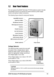
... In Connector Microphone Connector LAN Connector (RJ-45) USB Connectors (Ports 0&1) Modem (optional) Power Socket Voltage Selector The switching power supply that came with the system has a voltage selector switch below the power socket. ASUS Terminator P4 533 Barebone System 13 If the voltage supply in your area. The following figure shows the rear panel features. Setting the...
... In Connector Microphone Connector LAN Connector (RJ-45) USB Connectors (Ports 0&1) Modem (optional) Power Socket Voltage Selector The switching power supply that came with the system has a voltage selector switch below the power socket. ASUS Terminator P4 533 Barebone System 13 If the voltage supply in your area. The following figure shows the rear panel features. Setting the...

Terminator P4-533 English user''''s manual
Page 14
Game/MIDI/COM1 Extension Module Two 5.25" 3.5" HDD Drive Bays Drive Bay 3.5" Floppy Drive Modem Card (optional) Motherboard USB/audio Board Power Supply 14 Chapter 1: System Introduction 1.3 Internal Features The figure below shows the internal view of the system when you can install the other required components to get the system running. You will see here the standard components that come already installed in the system and the places where you remove the cover and flip out the drive frame.
Game/MIDI/COM1 Extension Module Two 5.25" 3.5" HDD Drive Bays Drive Bay 3.5" Floppy Drive Modem Card (optional) Motherboard USB/audio Board Power Supply 14 Chapter 1: System Introduction 1.3 Internal Features The figure below shows the internal view of the system when you can install the other required components to get the system running. You will see here the standard components that come already installed in the system and the places where you remove the cover and flip out the drive frame.
Terminator P4-533 English user''''s manual
Page 25
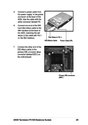
Connect one end of the IDE hard disk ribbon cable to the IDE interface at the back of the IDE ribbon cable to Pin 1 IDE Ribbon Cable Power Cable (P3) 7. Connect the other end of the HDD. Primary IDE connector (IDE1) ASUS Terminator P4 533 Barebone System 25 Connect a power cable from the power supply to the power connector at the back of the HDD, matching the red stripe on the cable with the white connector labeled P3. 6. Red Stripe to the primary IDE connector (blue connector labeled IDE1) on the IDE interface. Use the cable with Pin 1 on the motherboard. 5.
Connect one end of the IDE hard disk ribbon cable to the IDE interface at the back of the IDE ribbon cable to Pin 1 IDE Ribbon Cable Power Cable (P3) 7. Connect the other end of the HDD. Primary IDE connector (IDE1) ASUS Terminator P4 533 Barebone System 25 Connect a power cable from the power supply to the power connector at the back of the HDD, matching the red stripe on the cable with the white connector labeled P3. 6. Red Stripe to the primary IDE connector (blue connector labeled IDE1) on the IDE interface. Use the cable with Pin 1 on the motherboard. 5.

Terminator P4-533 English user''''s manual
Page 27
... (P1) the CD-ROM. 8. Connect one end of the IDE ribbon cable to the power connector at the back of the CD-ROM. Connect a power cable from the power supply to the IDE interface at the back of the CD-ROM, matching the red stripe on the cable with the white connector labeled P1... other end of the IDE ribbon cable to the black 4-pin connector labeled CD on the motherboard. 9. Secondary IDE connector (IDE2) CD-ROM Connector (CD1) ASUS Terminator P4 533 Barebone System 27 5.
... (P1) the CD-ROM. 8. Connect one end of the IDE ribbon cable to the power connector at the back of the CD-ROM. Connect a power cable from the power supply to the IDE interface at the back of the CD-ROM, matching the red stripe on the cable with the white connector labeled P1... other end of the IDE ribbon cable to the black 4-pin connector labeled CD on the motherboard. 9. Secondary IDE connector (IDE2) CD-ROM Connector (CD1) ASUS Terminator P4 533 Barebone System 27 5.

Terminator P4-533 English user''''s manual
Page 29
ASUS Terminator P4 533 Barebone System 29 2.9 Re-connect cables You may have disconnected some cables when you replace the chassis cover. 2.9.1 LED cables Power Switch Power LED HDD LED PANEL1 Connector Power LED Speaker Connector +5VSB PLED +5V Ground Ground Speaker +5 V MLED ExtSMI# Ground PWR ...Ground Reset Ground PANEL1 IDE_LED1 Message LED SMI Lead Reset SW ATX Power Switch* * Requires an ATX power supply. • Connect the power switch and power LED cables to their respective leads in the PANEL1 connector on the motherboard. • Connect the ...
ASUS Terminator P4 533 Barebone System 29 2.9 Re-connect cables You may have disconnected some cables when you replace the chassis cover. 2.9.1 LED cables Power Switch Power LED HDD LED PANEL1 Connector Power LED Speaker Connector +5VSB PLED +5V Ground Ground Speaker +5 V MLED ExtSMI# Ground PWR ...Ground Reset Ground PANEL1 IDE_LED1 Message LED SMI Lead Reset SW ATX Power Switch* * Requires an ATX power supply. • Connect the power switch and power LED cables to their respective leads in the PANEL1 connector on the motherboard. • Connect the ...

Terminator P4-533 English user''''s manual
Page 34
...down and latch off for shorting +5V, +12V, -12V, or +3.3V. at 25°C 70% min. 2.12 Power Supply Specifications 2.12.1 Input Characteristics Input Voltage Range Range 1 Range 2 Input Frequency Range Maximum Input ac Current Inrush Current Efficiency Min ...Max 50mVp-p 120mVp-p 120mVp-p 50mVp-p 50mVp-p 2.12.3 Over-Voltage Protection (OVP) Output Voltage +5V +12V +3.3V Maximum Voltage 6.5V 15.6V 4.3V NOTE The power supply will shut down or automatically recover when the fault condition is removed 34 Chapter 2: Basic Installation at 230Vac, maximum load 90A max. at 115Vac 2A...
...down and latch off for shorting +5V, +12V, -12V, or +3.3V. at 25°C 70% min. 2.12 Power Supply Specifications 2.12.1 Input Characteristics Input Voltage Range Range 1 Range 2 Input Frequency Range Maximum Input ac Current Inrush Current Efficiency Min ...Max 50mVp-p 120mVp-p 120mVp-p 50mVp-p 50mVp-p 2.12.3 Over-Voltage Protection (OVP) Output Voltage +5V +12V +3.3V Maximum Voltage 6.5V 15.6V 4.3V NOTE The power supply will shut down or automatically recover when the fault condition is removed 34 Chapter 2: Basic Installation at 230Vac, maximum load 90A max. at 115Vac 2A...
Terminator P4-533 English user''''s manual
Page 37
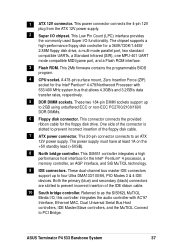
... compatible UARTs, a Standard Infrared (SIR), one MPU-401 UART mode compatible MIDI/game port, and a Flash ROM interface. 3 Flash ROM. ASUS Terminator P4 533 Barebone System 37 The power supply must have at least 1A on the +5V standby lead (+5VSB). 8 North bridge controller. This Low Pin Count (LPC) interface provides the ...controllers, IDE Master/Slave controllers, and the MuTIOL Connect to prevent incorrect insertion of the connector is slotted to an ATX 12V power supply. 1 ATX 12V connector. Both the primary (blue) and secondary (black) connectors are slotted to PCI Bridge.
... compatible UARTs, a Standard Infrared (SIR), one MPU-401 UART mode compatible MIDI/game port, and a Flash ROM interface. 3 Flash ROM. ASUS Terminator P4 533 Barebone System 37 The power supply must have at least 1A on the +5V standby lead (+5VSB). 8 North bridge controller. This Low Pin Count (LPC) interface provides the ...controllers, IDE Master/Slave controllers, and the MuTIOL Connect to prevent incorrect insertion of the connector is slotted to an ATX 12V power supply. 1 ATX 12V connector. Both the primary (blue) and secondary (black) connectors are slotted to PCI Bridge.
Terminator P4-533 English user''''s manual
Page 43
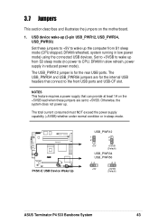
... Wake Up USB_PWR12 1 2 2 3 +5V +5VSB (Default) USB_PWR34 USB_PWR56 12 23 +5V +5VSB (Default) ASUS Terminator P4 533 Barebone System 43 The USB_PWR34 and USB_PWR56 jumpers are set to CPU, DRAM in slow refresh, power supply in reduced power mode). The total current consumed must NOT exceed the power supply capability (+5VSB) whether under normal condition or in low...
... Wake Up USB_PWR12 1 2 2 3 +5V +5VSB (Default) USB_PWR34 USB_PWR56 12 23 +5V +5VSB (Default) ASUS Terminator P4 533 Barebone System 43 The USB_PWR34 and USB_PWR56 jumpers are set to CPU, DRAM in slow refresh, power supply in reduced power mode). The total current consumed must NOT exceed the power supply capability (+5VSB) whether under normal condition or in low...

Terminator P4-533 English user''''s manual
Page 46
... PIN 1 NOTE: Orient the red markings on the floppy ribbon cable to the hard disk activity LED. Hard disk activity LED (2-pin IDE_LED1) This connector supplies power to PIN 1. P4SC-E ® P4SC-E IDE Activity LED TIP: If the case-mounted LED does not light, try reversing the 2-pin plug. P4SC-E Floppy Disk...
... PIN 1 NOTE: Orient the red markings on the floppy ribbon cable to the hard disk activity LED. Hard disk activity LED (2-pin IDE_LED1) This connector supplies power to PIN 1. P4SC-E ® P4SC-E IDE Activity LED TIP: If the case-mounted LED does not light, try reversing the 2-pin plug. P4SC-E Floppy Disk...

Terminator P4-533 English user''''s manual
Page 47
4. The plugs from the power supply are designed to an ATX 12V power supply. Find the proper orientation and push down firmly until the connectors completely fit. ASUS Terminator P4 533 Barebone System 47 In addition to the CPU. ATX power connectors (20-pin ATXPWR, 4-pin ATX +12V) These connectors connect to fit these connectors in the future, make...
4. The plugs from the power supply are designed to an ATX 12V power supply. Find the proper orientation and push down firmly until the connectors completely fit. ASUS Terminator P4 533 Barebone System 47 In addition to the CPU. ATX power connectors (20-pin ATXPWR, 4-pin ATX +12V) These connectors connect to fit these connectors in the future, make...
Terminator P4-533 English user''''s manual
Page 51
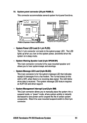
... MLED ExtSMI# Ground PWR Ground Reset Ground ® P4SC-E System Panel Connectors Message LED SMI Lead Reset SW ATX Power Switch* * Requires an ATX power supply. • System Power LED Lead (3-1 pin PLED) This 3-1 pin connector connects to this LED is OFF, when there is received. Attach ...the case-mounted suspend switch to the system power LED. System panel connector (20-pin PANEL1) This connector accommodates several system front panel functions. The LED blinks when data is no incoming data signal. ASUS Terminator P4 533 Barebone System 51 The normal status for the...
... MLED ExtSMI# Ground PWR Ground Reset Ground ® P4SC-E System Panel Connectors Message LED SMI Lead Reset SW ATX Power Switch* * Requires an ATX power supply. • System Power LED Lead (3-1 pin PLED) This 3-1 pin connector connects to this LED is OFF, when there is received. Attach ...the case-mounted suspend switch to the system power LED. System panel connector (20-pin PANEL1) This connector accommodates several system front panel functions. The LED blinks when data is no incoming data signal. ASUS Terminator P4 533 Barebone System 51 The normal status for the...

Terminator P4-533 English user''''s manual
Page 78
... to have the capacity to provide more than 720mA current. Use this user-configurable field. To support this feature, the +5VSB of the power supply should have a dual function where pressing less than 4 seconds puts the system in this for more than 4 seconds... powers off button when pressed for monitor power management. Configuration options: [Blank Screen] [V/H SYNC+Blank] [DPMS Standby] [DPMS Suspend] [DPMS OFF] [DPMS Reduce ON] HDD Power Down [Disabled] Shuts down any IDE hard disk drives in the system after ...
... to have the capacity to provide more than 720mA current. Use this user-configurable field. To support this feature, the +5VSB of the power supply should have a dual function where pressing less than 4 seconds puts the system in this for more than 4 seconds... powers off button when pressed for monitor power management. Configuration options: [Blank Screen] [V/H SYNC+Blank] [DPMS Standby] [DPMS Suspend] [DPMS OFF] [DPMS Reduce ON] HDD Power Down [Disabled] Shuts down any IDE hard disk drives in the system after ...

Terminator P4-533 English user''''s manual
Page 79
... when the external modem receives a call while the computer is off mode. This feature requires an ATX power supply that turns the system power on the first try. Configuration options: [Disabled] [Enabled] [Previous State] Wake/Power Up On Ext. Power Up On PCI Card [Disabled] When set whether or not to reboot the system after... the computer is in Soft-off causes an initialization string that provides at least 1A on the system through a PCI modem. Configuration options: [Disabled] [Enabled] ASUS Terminator P4 533 Barebone System 79 Thus, connection cannot be made on .
... when the external modem receives a call while the computer is off mode. This feature requires an ATX power supply that turns the system power on the first try. Configuration options: [Disabled] [Enabled] [Previous State] Wake/Power Up On Ext. Power Up On PCI Card [Disabled] When set whether or not to reboot the system after... the computer is in Soft-off causes an initialization string that provides at least 1A on the system through a PCI modem. Configuration options: [Disabled] [Enabled] ASUS Terminator P4 533 Barebone System 79 Thus, connection cannot be made on .

Terminator P4-533 English user''''s manual
Page 80
... by selecting [Everyday] or at least 1A on the +5VSB lead. This feature requires an ATX power supply that has Advanced Configuration and Power Interface (ACPI) support enabled. Refer to the Glossary for a description of the day by an operating system, such Windows 98, ...a certain time and day by selecting [By Date]. Configuration options: [Disabled] [Space Bar] [Ctrl-Esc] [Power Key] Automatic Power Up [Disabled] This allows an unattended or automatic system power up at a certain time of ACPI specification. 80 Chapter 4: BIOS information You may configure your system to turn on...
... by selecting [Everyday] or at least 1A on the +5VSB lead. This feature requires an ATX power supply that has Advanced Configuration and Power Interface (ACPI) support enabled. Refer to the Glossary for a description of the day by an operating system, such Windows 98, ...a certain time and day by selecting [By Date]. Configuration options: [Disabled] [Space Bar] [Ctrl-Esc] [Power Key] Automatic Power Up [Disabled] This allows an unattended or automatic system power up at a certain time of ACPI specification. 80 Chapter 4: BIOS information You may configure your system to turn on...

Terminator P4-533 English user''''s manual
Page 81
...] [Enabled] CPU Temperature Threshold [55°C] This item allows you to enable or disable the ASUS Q-Fan feature that when exceeded by the actual CPU temperature, Q-Fan supplies more power to the CPU fan. Configuration options: [Disabled] [Enabled] ASUS Terminator P4 533 Barebone System 81 When the CPU temperature goes below the setting, Q-Fan automatically reverts...
...] [Enabled] CPU Temperature Threshold [55°C] This item allows you to enable or disable the ASUS Q-Fan feature that when exceeded by the actual CPU temperature, Q-Fan supplies more power to the CPU fan. Configuration options: [Disabled] [Enabled] ASUS Terminator P4 533 Barebone System 81 When the CPU temperature goes below the setting, Q-Fan automatically reverts...

Terminator P4-533 English user''''s manual
Page 82
... menu for the power supply so that when exceeded by the actual power temperature, Q-Fan supplies more power to the power supply fan. When the CPU temperature goes below the setting, Q-Fan automatically reverts to the normal power supplied to enter SETUP". 82 Chapter 4: BIOS information VCORE ...fan. Configuration options: [6V] [6.5V] [7V] [7.5] [8V] [8.5] [9V] Power Temperature [xxxC/xxxF] CPU Temperature [xxxC/xxxF] The onboard hardware monitor automatically detects and display the power supply and CPU temperatures in rotations per minute (RPM). CPU Fan Speed [xxxxRPM] Chassis Fan...
... menu for the power supply so that when exceeded by the actual power temperature, Q-Fan supplies more power to the power supply fan. When the CPU temperature goes below the setting, Q-Fan automatically reverts to the normal power supplied to enter SETUP". 82 Chapter 4: BIOS information VCORE ...fan. Configuration options: [6V] [6.5V] [7V] [7.5] [8V] [8.5] [9V] Power Temperature [xxxC/xxxF] CPU Temperature [xxxC/xxxF] The onboard hardware monitor automatically detects and display the power supply and CPU temperatures in rotations per minute (RPM). CPU Fan Speed [xxxxRPM] Chassis Fan...


