User Manual
Page 1
TW300-E5/PI4 Intel® LGA775 Core™ 2 Extreme / Core™ 2 Quad / Core™ 2 Duo Series Workstation User's Manaual
TW300-E5/PI4 Intel® LGA775 Core™ 2 Extreme / Core™ 2 Quad / Core™ 2 Duo Series Workstation User's Manaual
User Manual
Page 2
... by the purchaser for backup purposes, without warranty of any language in this manual, including the products and software described in writing by ASUS; ASUS provides this manual, including the products and software described in it . E3822 First Edition May 2008 Copyright © 2008 ASUSTeK COMPUTER INC... only for loss of profits, loss of business, loss of use or data, interruption of business and the like), even if ASUS has been advised of the possibility of their respective companies, and are subject to infringe. ii Specifications and information contained in this ...
... by the purchaser for backup purposes, without warranty of any language in this manual, including the products and software described in writing by ASUS; ASUS provides this manual, including the products and software described in it . E3822 First Edition May 2008 Copyright © 2008 ASUSTeK COMPUTER INC... only for loss of profits, loss of business, loss of use or data, interruption of business and the like), even if ASUS has been advised of the possibility of their respective companies, and are subject to infringe. ii Specifications and information contained in this ...
User Manual
Page 3
Contents Contents...iii Notices...viii Safety information ix About this guide x Chapter 1: Product introduction 1.1 System package contents 1-2 1.2 Serial number label 1-2 1.3 System specifications 1-3 1.4 Front panel features 1-5 1.5 Rear panel features 1-6 1.6 Internal features 1-7 1.7 LED information 1-8 1.7.1 Front panel LEDs 1-8 1.7.2 LAN (RJ-45) LEDs 1-8 Chapter 2: Hardware setup 2.1 Chassis cover 2-2 2.1.1 Removing the left side cover 2-2 2.1.2 Removing the right side cover 2-3 2.2 Motherboard overview 2-4 2.3 Central Processing Unit (CPU 2-5 2.3.1 Installing the CPU ...
Contents Contents...iii Notices...viii Safety information ix About this guide x Chapter 1: Product introduction 1.1 System package contents 1-2 1.2 Serial number label 1-2 1.3 System specifications 1-3 1.4 Front panel features 1-5 1.5 Rear panel features 1-6 1.6 Internal features 1-7 1.7 LED information 1-8 1.7.1 Front panel LEDs 1-8 1.7.2 LAN (RJ-45) LEDs 1-8 Chapter 2: Hardware setup 2.1 Chassis cover 2-2 2.1.1 Removing the left side cover 2-2 2.1.2 Removing the right side cover 2-3 2.2 Motherboard overview 2-4 2.3 Central Processing Unit (CPU 2-5 2.3.1 Installing the CPU ...
User Manual
Page 4
... info 3.1 Motherboard layouts 3-2 3.2 Jumpers 3-6 3.3 Connectors 3-8 3.3.1 Rear panel connectors 3-8 3.3.2 Internal connectors 3-11 Chapter 4: BIOS infomation 4.1 Managing and updating your BIOS 4-2 4.1.1 ASUS Update utility 4-2 4.1.2 Creating a bootable floppy disk 4-5 4.1.3 ASUS EZ Flash 2 utility 4-6 4.1.4 AFUDOS utility 4-7 4.1.5 ASUS CrashFree BIOS 3 utility 4-9 4.2 BIOS setup program 4-10 4.2.1 BIOS menu screen 4-11 4.2.2 Menu bar 4-11 4.2.3 Navigation keys 4-11 4.2.4 Menu items 4-12...
... info 3.1 Motherboard layouts 3-2 3.2 Jumpers 3-6 3.3 Connectors 3-8 3.3.1 Rear panel connectors 3-8 3.3.2 Internal connectors 3-11 Chapter 4: BIOS infomation 4.1 Managing and updating your BIOS 4-2 4.1.1 ASUS Update utility 4-2 4.1.2 Creating a bootable floppy disk 4-5 4.1.3 ASUS EZ Flash 2 utility 4-6 4.1.4 AFUDOS utility 4-7 4.1.5 ASUS CrashFree BIOS 3 utility 4-9 4.2 BIOS setup program 4-10 4.2.1 BIOS menu screen 4-11 4.2.2 Menu bar 4-11 4.2.3 Navigation keys 4-11 4.2.4 Menu items 4-12...
User Manual
Page 6
...4-33 4.7 Boot menu 4-35 4.7.1 Boot Device Priority 4-35 4.7.2 Boot Settings Configuration 4-36 4.7.3 Security 4-37 4.8 Tools menu 4-39 4.8.1 ASUS EZ Flash 2 4-39 4.8.2 ASUS O.C. Profile 4-40 4.8.3 Ai Net 2 4-41 4.9 Exit menu 4-42 Chapter 5: RAID configuration 5.1 RAID configurations 5-2 5.1.1 RAID definitions 5-2 5.1.2... Rebuilding the RAID 5-17 5.3.8 Exiting the Intel® Matrix Storage Manager 5-20 5.3.9 Setting the Boot array use MB BIOS Setup Utility......... 5-20 5.3.10 Global Array Manager 5-21 Chapter 6: Driver installation 6.1 RAID driver installation 6-2 6.1.1 Creating a...
...4-33 4.7 Boot menu 4-35 4.7.1 Boot Device Priority 4-35 4.7.2 Boot Settings Configuration 4-36 4.7.3 Security 4-37 4.8 Tools menu 4-39 4.8.1 ASUS EZ Flash 2 4-39 4.8.2 ASUS O.C. Profile 4-40 4.8.3 Ai Net 2 4-41 4.9 Exit menu 4-42 Chapter 5: RAID configuration 5.1 RAID configurations 5-2 5.1.1 RAID definitions 5-2 5.1.2... Rebuilding the RAID 5-17 5.3.8 Exiting the Intel® Matrix Storage Manager 5-20 5.3.9 Setting the Boot array use MB BIOS Setup Utility......... 5-20 5.3.10 Global Array Manager 5-21 Chapter 6: Driver installation 6.1 RAID driver installation 6-2 6.1.1 Creating a...

User Manual
Page 7
... 6-7 6.2.3 Utilities menu 6-8 6.2.4 Make Disk menu 6-10 6.2.5 Manual menu 6-11 6.2.6 ASUS Contact information 6-11 6.2.7 Other information 6-12 6.3 Software information 6-14 6.3.1 ASUS MyLogo2 6-14 6.3.2 Audio configurations 6-16 6.3.3 ASUS PC Probe II 6-24 6.3.4 ASUS AI Suite 6-30 6.3.5 ASUS AI Gear 2 6-32 6.3.6 ASUS AI Nap 6-33 6.3.7 ASUS AI N.O.S 6-34 6.3.8 ASUS Q-Fan 2 6-35 6.3.9 ASUS AI Booster 6-36 Appendix: Reference information A.1 Intel® EM64T A-2 Using...
... 6-7 6.2.3 Utilities menu 6-8 6.2.4 Make Disk menu 6-10 6.2.5 Manual menu 6-11 6.2.6 ASUS Contact information 6-11 6.2.7 Other information 6-12 6.3 Software information 6-14 6.3.1 ASUS MyLogo2 6-14 6.3.2 Audio configurations 6-16 6.3.3 ASUS PC Probe II 6-24 6.3.4 ASUS AI Suite 6-30 6.3.5 ASUS AI Gear 2 6-32 6.3.6 ASUS AI Nap 6-33 6.3.7 ASUS AI N.O.S 6-34 6.3.8 ASUS Q-Fan 2 6-35 6.3.9 ASUS AI Booster 6-36 Appendix: Reference information A.1 Intel® EM64T A-2 Using...

User Manual
Page 8
WARNING! Canadian Department of Communications Statement This digital apparatus does not exceed the Class B limits for radio noise emissions from that may cause undesired operation. Check local regulations for disposal of the monitor to the graphics card is required to provide reasonable protection against harmful interference in a residential installation. This equipment generates, uses and can be placed in the Radio Interference Regulations of the Canadian Department of the following two conditions: • This device may cause harmful interference to radio communications....
WARNING! Canadian Department of Communications Statement This digital apparatus does not exceed the Class B limits for radio noise emissions from that may cause undesired operation. Check local regulations for disposal of the monitor to the graphics card is required to provide reasonable protection against harmful interference in a residential installation. This equipment generates, uses and can be placed in the Radio Interference Regulations of the Canadian Department of the following two conditions: • This device may cause harmful interference to radio communications....
User Manual
Page 9
If any additional devices to the manufacturer's instructions. This product is to be performed by the manufacturer. Use the power cable with a properly grounded electrical outlet to fix it by yourself. Replace only with the same or equivalent type recommended by trained service personnel only. • Before operating the server, carefully read all the manuals included with a three-wire power cable and plug for assistance when moving or carrying the system. Dispose of explosion if battery is detected, contact your dealer as soon as possible. • To avoid short ...
If any additional devices to the manufacturer's instructions. This product is to be performed by the manufacturer. Use the power cable with a properly grounded electrical outlet to fix it by yourself. Replace only with the same or equivalent type recommended by trained service personnel only. • Before operating the server, carefully read all the manuals included with a three-wire power cable and plug for assistance when moving or carrying the system. Dispose of explosion if battery is detected, contact your dealer as soon as possible. • To avoid short ...
User Manual
Page 10
Chapter 2: Hardware setup This chapter lists the hardware setup procedures that comes with at least basic knowledge of the workstation, including sections on front panel and rear panel specifications. 2. Chapter 5: RAID configuration This chapter provides information on how to change system settings through the BIOS Setup menus and describes the BIOS parameters. 5. Chapter 1: Product Introduction This chapter describes the general features of configuring a workstation. Chapter 3: Motherboard information This chapter gives information about the CPU features and technologies and ...
Chapter 2: Hardware setup This chapter lists the hardware setup procedures that comes with at least basic knowledge of the workstation, including sections on front panel and rear panel specifications. 2. Chapter 5: RAID configuration This chapter provides information on how to change system settings through the BIOS Setup menus and describes the BIOS parameters. 5. Chapter 1: Product Introduction This chapter describes the general features of configuring a workstation. Chapter 3: Motherboard information This chapter gives information about the CPU features and technologies and ...

User Manual
Page 11
...Instructions that you perform certain tasks properly, take note of the following symbols used throughout this manual. xi Refer to the ASUS contact information for all ASUS hardware and software products. Conventions To make sure that you MUST follow to complete a task. CAUTION: Information to prevent damage... to the components when trying to aid in completing a task. Reference Visit the ASUS websites worldwide that provide updated information for details. WARNING: Information to prevent injury to yourself when trying to complete a task.
...Instructions that you perform certain tasks properly, take note of the following symbols used throughout this manual. xi Refer to the ASUS contact information for all ASUS hardware and software products. Conventions To make sure that you MUST follow to complete a task. CAUTION: Information to prevent damage... to the components when trying to aid in completing a task. Reference Visit the ASUS websites worldwide that provide updated information for details. WARNING: Information to prevent injury to yourself when trying to complete a task.

User Manual
Page 13
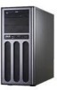
Product introduction Chapter 1 This chapter describes the general features of the workstation, including sections on front panel and rear panel specifications. ASUS TW300-E5/PI4 1-
Product introduction Chapter 1 This chapter describes the general features of the workstation, including sections on front panel and rear panel specifications. ASUS TW300-E5/PI4 1-

User Manual
Page 14
... following items. Model Name Chassis Motherboard Component Accessories Optional Items TW300-E5/PI4 ASUS T10 Pedestal Chassis ASUS P5E WS Professional 1 x 450W Single Power Supply 1 x 95mm System Fan 5 x SATA Cables 1 x 7-in-1 Card Reader 4 x Internal HDD trays 1 x Front I/O Board 1 x ASUS TW300-E5/PI4 User's Guide 1 x TW300-E5/PI4 Support CD 1 x Bag of the product, ASUS Technical Support team members can then offer a quicker and...
... following items. Model Name Chassis Motherboard Component Accessories Optional Items TW300-E5/PI4 ASUS T10 Pedestal Chassis ASUS P5E WS Professional 1 x 450W Single Power Supply 1 x 95mm System Fan 5 x SATA Cables 1 x 7-in-1 Card Reader 4 x Internal HDD trays 1 x Front I/O Board 1 x ASUS TW300-E5/PI4 User's Guide 1 x TW300-E5/PI4 Support CD 1 x Bag of the product, ASUS Technical Support team members can then offer a quicker and...

User Manual
Page 15
...Supports software RAID 0, 1, 5, and 10 (for Windows only) - 1.3 System specifications The ASUS TW300-E5/PI4 is a workstation featuring the ASUS P5E WS Professional motherboard. Model Name TW300-E5/PI4 1 x Socket LGA775 Processor / System Bus Quad-core: Intel® Core™ 2 Extreme...10 (for Linux) HDD Bays I = internal A or S will be hot-swappable 4 x Internal SATAII HDD Bays (continued on the next page) ASUS TW300-E5/PI4 1-3 Supports software RAID 0, 1, 5 and 10 Marvell 88SE6145 SATA Controller: - The workstation supports Intel® LGA775 Core™ 2 Extreme / Core&#...
...Supports software RAID 0, 1, 5, and 10 (for Windows only) - 1.3 System specifications The ASUS TW300-E5/PI4 is a workstation featuring the ASUS P5E WS Professional motherboard. Model Name TW300-E5/PI4 1 x Socket LGA775 Processor / System Bus Quad-core: Intel® Core™ 2 Extreme...10 (for Linux) HDD Bays I = internal A or S will be hot-swappable 4 x Internal SATAII HDD Bays (continued on the next page) ASUS TW300-E5/PI4 1-3 Supports software RAID 0, 1, 5 and 10 Marvell 88SE6145 SATA Controller: - The workstation supports Intel® LGA775 Core™ 2 Extreme / Core&#...

User Manual
Page 16
... to change without notice. 1-4 Chapter 1: Product introduction NVIDIA Quadro FX370 (256 MB, up to 2 cards) Onboard I/O 1 x PS/2 keyboard port 2 x RJ-45 ports 1 x S/PDIF Out port (Coaxial + Optical) 8 x USB 2.0 ports (Front x 2, Rear x 6) 2 x eSATA ports 1 x IEEE1394a port 6 x Audio ports ... Reader 2 x 5.25" Optical Drives (Options: 16X DVD-ROM / DVD-RW) Graphic VGA Graphic Add-on Card Configuration Option: Option 1: Professional 2D - NVIDIA Quadro FX570 (256 MB, up to 2 cards) Option 3: Mid-range 3D - NVIDIA Quadro NVS290 (256...
... to change without notice. 1-4 Chapter 1: Product introduction NVIDIA Quadro FX370 (256 MB, up to 2 cards) Onboard I/O 1 x PS/2 keyboard port 2 x RJ-45 ports 1 x S/PDIF Out port (Coaxial + Optical) 8 x USB 2.0 ports (Front x 2, Rear x 6) 2 x eSATA ports 1 x IEEE1394a port 6 x Audio ports ... Reader 2 x 5.25" Optical Drives (Options: 16X DVD-ROM / DVD-RW) Graphic VGA Graphic Add-on Card Configuration Option: Option 1: Professional 2D - NVIDIA Quadro FX570 (256 MB, up to 2 cards) Option 3: Mid-range 3D - NVIDIA Quadro NVS290 (256...
User Manual
Page 17
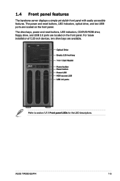
... features. The drive bays, power and reset buttons, LED indicators, CD/DVD-ROM drive, floppy drive, and USB 2.0 ports are located on the front panel. ASUS TW300-E5/PI4 1-5 Optical Drive Empty 5.25-inch bay 7-in-1 Card Reader Power button Reset button Power LED HDD access LED USB 2.0 ports Refer to section 1.7.1 Front panel...
... features. The drive bays, power and reset buttons, LED indicators, CD/DVD-ROM drive, floppy drive, and USB 2.0 ports are located on the front panel. ASUS TW300-E5/PI4 1-5 Optical Drive Empty 5.25-inch bay 7-in-1 Card Reader Power button Reset button Power LED HDD access LED USB 2.0 ports Refer to section 1.7.1 Front panel...
User Manual
Page 18
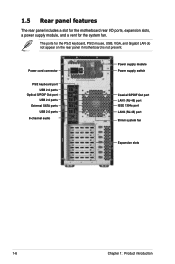
Power cord connector PS/2 keyboard port USB 2.0 ports Optical S/PDIF Out port USB 2.0 ports External SATA ports USB 2.0 ports 8-channel audio Power supply module Power supply switch Coaxial S/PDIF Out port LAN1 (RJ-45) port IEEE 1394a port LAN2 (RJ-45) port 95mm system fan Expansion slots 1-6 Chapter 1: Product introduction The ports for the system fan. 1.5 Rear panel features The rear panel includes a slot for the motherboard rear I/O ports, expansion slots, a power supply module, and a vent for the PS/2 keyboard, PS/2 mouse, USB, VGA, and Gigabit LAN do not appear on the rear panel ...
Power cord connector PS/2 keyboard port USB 2.0 ports Optical S/PDIF Out port USB 2.0 ports External SATA ports USB 2.0 ports 8-channel audio Power supply module Power supply switch Coaxial S/PDIF Out port LAN1 (RJ-45) port IEEE 1394a port LAN2 (RJ-45) port 95mm system fan Expansion slots 1-6 Chapter 1: Product introduction The ports for the system fan. 1.5 Rear panel features The rear panel includes a slot for the motherboard rear I/O ports, expansion slots, a power supply module, and a vent for the PS/2 keyboard, PS/2 mouse, USB, VGA, and Gigabit LAN do not appear on the rear panel ...

User Manual
Page 19
ASUS P5E WS Professional motherboard 4. Chassis intrusion switch ASUS TW300-E5/PI4 1-7 Optical drive 6. 5.25-inch drive bay 7. 7-in-1 Card Reader 8. Front I/O board (hidden) 9. Internal HDD bays 10. Expansion card locks 5. Power supply unit 2. 95mm system fan 3. 1.6 Internal features The barebone server includes the basic components as shown. 1 10 2 3 5 6 7 8 4 9 1.
ASUS P5E WS Professional motherboard 4. Chassis intrusion switch ASUS TW300-E5/PI4 1-7 Optical drive 6. 5.25-inch drive bay 7. 7-in-1 Card Reader 8. Front I/O board (hidden) 9. Internal HDD bays 10. Expansion card locks 5. Power supply unit 2. 95mm system fan 3. 1.6 Internal features The barebone server includes the basic components as shown. 1 10 2 3 5 6 7 8 4 9 1.

User Manual
Page 20
1.7 LED information 1.7.1 Front panel LEDs HDD Access LED Power LED LED Power LED HDD Access LED Icon Display status Description ON System power ON OFF Blinking No activity Read/write data into the HDD 1.7.2 LAN (RJ-45) LEDs ACT/LINK LED SPEED LED ACT/LINK LED SPEED LED ACT/LINK LED Status Description OFF No link GREEN Linked BLINKING Data activity SPEED LED Status Description OFF 10 Mbps connection ORANGE 100 Mbps connection GREEN 1 Gbps connection 1-8 Chapter 1: Product introduction
1.7 LED information 1.7.1 Front panel LEDs HDD Access LED Power LED LED Power LED HDD Access LED Icon Display status Description ON System power ON OFF Blinking No activity Read/write data into the HDD 1.7.2 LAN (RJ-45) LEDs ACT/LINK LED SPEED LED ACT/LINK LED SPEED LED ACT/LINK LED Status Description OFF No link GREEN Linked BLINKING Data activity SPEED LED Status Description OFF 10 Mbps connection ORANGE 100 Mbps connection GREEN 1 Gbps connection 1-8 Chapter 1: Product introduction
User Manual
Page 21
ASUS TW300-E5/PI4 2- Hardware setup Chapter 2 This chapter lists the hardware setup procedures that you have to perform when installing or removing system components.
ASUS TW300-E5/PI4 2- Hardware setup Chapter 2 This chapter lists the hardware setup procedures that you have to perform when installing or removing system components.

User Manual
Page 22
Slide the left side cover to install or replace internal components of the server system. • Ensure that you unplug the power cord before removing the side cover. • Take extra care when removing the side cover. Keep your fingers from the chassis. 3. Carefully lift the cover and set it is disengaged from components inside the chassis that secure the left side cover 1. Remove the two screws that can cause injury, such as the CPU fan, rear fan, and other sharp-edged parts. To remove the left side cover to the chassis. 1 2. 2.1 Chassis cover 2.1.1 Removing the left side...
Slide the left side cover to install or replace internal components of the server system. • Ensure that you unplug the power cord before removing the side cover. • Take extra care when removing the side cover. Keep your fingers from the chassis. 3. Carefully lift the cover and set it is disengaged from components inside the chassis that secure the left side cover 1. Remove the two screws that can cause injury, such as the CPU fan, rear fan, and other sharp-edged parts. To remove the left side cover to the chassis. 1 2. 2.1 Chassis cover 2.1.1 Removing the left side...