User Manual
Page 12
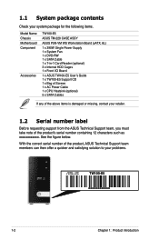
... figure below. 1.1 System package contents Check your system package for the following items. Model Name Chassis Motherboard Component Accessories TW100-E5 ASUS TM-220 CASE ASSY ASUS P5N-VM WS Workstation Board (uATX, 6L) 1 x 390W Single Power Supply 1 x System Fan 1 x DVD-RW 1 x SATA Cable 1 x 7-in-1 Card Reader (optional) 3 x Internal HDD Cages 1 x Front I/O Board 1 x ASUS TW100-E5 User's Guide 1 x TW100-E5 Support CD 1 x Bag of Screws 1 x AC Power Cable 1 x CPU Heatsink (optional) 5 x SATA Cables If any of the product's serial number containing 12 characters such as xxxxxxxxxxxx.
... figure below. 1.1 System package contents Check your system package for the following items. Model Name Chassis Motherboard Component Accessories TW100-E5 ASUS TM-220 CASE ASSY ASUS P5N-VM WS Workstation Board (uATX, 6L) 1 x 390W Single Power Supply 1 x System Fan 1 x DVD-RW 1 x SATA Cable 1 x 7-in-1 Card Reader (optional) 3 x Internal HDD Cages 1 x Front I/O Board 1 x ASUS TW100-E5 User's Guide 1 x TW100-E5 Support CD 1 x Bag of Screws 1 x AC Power Cable 1 x CPU Heatsink (optional) 5 x SATA Cables If any of the product's serial number containing 12 characters such as xxxxxxxxxxxx.
User Manual
Page 13
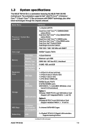
... (continued on Card (Support Hardware RAID 0, 1, 10 and 5) 3 x Internal SATA HDD Cages Networking LAN 2 x Realtek® RTL8111C Gigabit LAN controllers - 1.3 System specifications The ASUS TW100-E5 is a workstation featuring the ASUS P5N-VM WS motherboard. Model Name Processor / System Bus supported TW100-E5 1 x Socket LGA775 Quad-Core Intel® Core™ 2 QX9000/Q9000 series (45nm) Dual-Core Intel® Core™ 2 Duo E8000/E7000 series (45nm) Quad-Core Intel® Core™ 2 Q6000 series Dual-Core Intel...
... (continued on Card (Support Hardware RAID 0, 1, 10 and 5) 3 x Internal SATA HDD Cages Networking LAN 2 x Realtek® RTL8111C Gigabit LAN controllers - 1.3 System specifications The ASUS TW100-E5 is a workstation featuring the ASUS P5N-VM WS motherboard. Model Name Processor / System Bus supported TW100-E5 1 x Socket LGA775 Quad-Core Intel® Core™ 2 QX9000/Q9000 series (45nm) Dual-Core Intel® Core™ 2 Duo E8000/E7000 series (45nm) Quad-Core Intel® Core™ 2 Q6000 series Dual-Core Intel...

User Manual
Page 33
... in section 2.1 Chassis covers to unplug the power cable before installing or removing any system components. Locate the three hooked tabs on the right side. 2.6.1 Removing the front panel cover To remove the front panel cover 1. 2.6 Installing 5.25-inch drives Ensure to remove the both side covers. 2. Before you can install a 5.25inch drive, you should first remove the front panel cover. Follow the instructions in the right figure. 3. Failure to do so may...
... in section 2.1 Chassis covers to unplug the power cable before installing or removing any system components. Locate the three hooked tabs on the right side. 2.6.1 Removing the front panel cover To remove the front panel cover 1. 2.6 Installing 5.25-inch drives Ensure to remove the both side covers. 2. Before you can install a 5.25inch drive, you should first remove the front panel cover. Follow the instructions in the right figure. 3. Failure to do so may...

User Manual
Page 37
... to the discrete graphics card first when using PCI cards on the next page. 3. Install the software drivers for information on the next page for details. Connect the VGA cable to the card. ASUS TW100-E5 2-19 7. Refer to the table on BIOS setup. 2. To use quad-display, enable both the onboard GPU and the discrete Quadro graphics card. Secure the card to the tables on shared slots, ensure that the drivers support "Share IRQ" or...
... to the discrete graphics card first when using PCI cards on the next page. 3. Install the software drivers for information on the next page for details. Connect the VGA cable to the card. ASUS TW100-E5 2-19 7. Refer to the table on BIOS setup. 2. To use quad-display, enable both the onboard GPU and the discrete Quadro graphics card. Secure the card to the tables on shared slots, ensure that the drivers support "Share IRQ" or...

User Manual
Page 43
The illustration below shows the location of the onboard LED. PS/2 keyboard / mouse combo port 2. DVI-I out ports 5. Center/Subwoofer port (orange) 7. USB 2.0 ports 3 and 4 14. Optical S/PDIF Out port 15. Rear Speaker Out port (black) 8. This is ON, in sleep mode, or in any motherboard component. LAN1 (RJ-45) port 6. Layout contents Jumper Clear RTC RAM (3-pin CLRTC) Rear panel connectors 1. Onboard LED The motherboard comes with a standby power LED that lights up to indicate that the system is a reminder that you should...
The illustration below shows the location of the onboard LED. PS/2 keyboard / mouse combo port 2. DVI-I out ports 5. Center/Subwoofer port (orange) 7. USB 2.0 ports 3 and 4 14. Optical S/PDIF Out port 15. Rear Speaker Out port (black) 8. This is ON, in sleep mode, or in any motherboard component. LAN1 (RJ-45) port 6. Layout contents Jumper Clear RTC RAM (3-pin CLRTC) Rear panel connectors 1. Onboard LED The motherboard comes with a standby power LED that lights up to indicate that the system is a reminder that you should...

User Manual
Page 45
...) RAM in CMOS, which include system setup information such as system passwords. Removing the cap will cause system boot failure! 3.2 Jumper Clear RTC RAM (3-pin CLRTC) This jumper allows you to pins 2-3. To erase the RTC RAM 1. Plug the power cord and turn ON the computer. 4. Keep the cap on CLRTC jumper default position. Hold down the key during the boot process and enter BIOS setup to pins 1-2. 3. The onboard button cell battery powers the RAM data in CMOS. If...
...) RAM in CMOS, which include system setup information such as system passwords. Removing the cap will cause system boot failure! 3.2 Jumper Clear RTC RAM (3-pin CLRTC) This jumper allows you to pins 2-3. To erase the RTC RAM 1. Plug the power cord and turn ON the computer. 4. Keep the cap on CLRTC jumper default position. Hold down the key during the boot process and enter BIOS setup to pins 1-2. 3. The onboard button cell battery powers the RAM data in CMOS. If...

User Manual
Page 46
... play HD DVD or Blu-Ray Disc, make sure to 1920x1200. The lower DVI-I compatible device and are HDCP compliant, allowing playback of HD DVDi, Blu-Ray and other protected content. • This motherboard comes with dual-DVI output that features different displays on 2 monitors at the same time if you connect 2 monitors to a Local Area Network (LAN) through a network hub. 3.3 Connectors 3.3.1 Rear panel connectors 1. ��...
... play HD DVD or Blu-Ray Disc, make sure to 1920x1200. The lower DVI-I compatible device and are HDCP compliant, allowing playback of HD DVDi, Blu-Ray and other protected content. • This motherboard comes with dual-DVI output that features different displays on 2 monitors at the same time if you connect 2 monitors to a Local Area Network (LAN) through a network hub. 3.3 Connectors 3.3.1 Rear panel connectors 1. ��...

User Manual
Page 48
... use SATA hard disk drives in the BIOS to [RAID mode] or [AHCI Mode]. • SATA devices connected to [IDE] by default. NVIDIA® Quadro FX470 Serial ATA connectors (7-pin SATA1-4 [red]; 7-pin SATA5-6 [black]) These connectors are for the Serial ATA signal cables for Serial ATA hard disk drives and optical disk drives. • SATA1-4 connectors are using SATA hard disk drives. The SATA RAID feature is available only if you may connect the right-angle side of SATA signal cable to avoid mechanical conflict with huge graphics cards. 3.3.2 Internal connectors 1. Connect the...
... use SATA hard disk drives in the BIOS to [RAID mode] or [AHCI Mode]. • SATA devices connected to [IDE] by default. NVIDIA® Quadro FX470 Serial ATA connectors (7-pin SATA1-4 [red]; 7-pin SATA5-6 [black]) These connectors are for the Serial ATA signal cables for Serial ATA hard disk drives and optical disk drives. • SATA1-4 connectors are using SATA hard disk drives. The SATA RAID feature is available only if you may connect the right-angle side of SATA signal cable to avoid mechanical conflict with huge graphics cards. 3.3.2 Internal connectors 1. Connect the...

User Manual
Page 56
... the optical drive. Place the support DVD in Windows® environment.) 2. ASUS AFUDOS (Updates the BIOS using a floppy disk or USB flash disk.) 3. The ASUS Update utility allows you to restore the BIOS in case you to the corresponding sections for details on these utilities. Click the Utilities tab, then click Install ASUS Update VX.XX.XX. 3. Save a copy of the original motherboard BIOS file to a bootable floppy disk or USB flash disk in the future. The Drivers menu appears. 2. ASUS Update requires an Internet connection...
... the optical drive. Place the support DVD in Windows® environment.) 2. ASUS AFUDOS (Updates the BIOS using a floppy disk or USB flash disk.) 3. The ASUS Update utility allows you to restore the BIOS in case you to the corresponding sections for details on these utilities. Click the Utilities tab, then click Install ASUS Update VX.XX.XX. 3. Save a copy of the original motherboard BIOS file to a bootable floppy disk or USB flash disk in the future. The Drivers menu appears. 2. ASUS Update requires an Internet connection...

User Manual
Page 63
... BIOS 3. ASUS TW100-E5 4-9 Bad BIOS checksum. The device size should be smaller than 8GB. • DO NOT shut down or reset the system while updating the BIOS! Floppy found , the utility reads the BIOS file and starts flashing the corrupted BIOS file. Prepare the motherboard support DVD, the floppy disk or the USB flash disk containing the updated motherboard BIOS before using the motherboard support DVD or the USB flash disk that contains the BIOS file to the USB port. 2. Insert the motherboard support DVD to restore...
... BIOS 3. ASUS TW100-E5 4-9 Bad BIOS checksum. The device size should be smaller than 8GB. • DO NOT shut down or reset the system while updating the BIOS! Floppy found , the utility reads the BIOS file and starts flashing the corrupted BIOS file. Prepare the motherboard support DVD, the floppy disk or the USB flash disk containing the updated motherboard BIOS before using the motherboard support DVD or the USB flash disk that contains the BIOS file to the USB port. 2. Insert the motherboard support DVD to restore...

User Manual
Page 64
...-menus and make your screen. • Visit the ASUS website (www.asus.com) to "Run Setup." For example, you are installing a motherboard, reconfiguring your BIOS. The firmware chip on the system chassis. You can also restart by pressing the reset button on the motherboard stores the Setup utility. See section 4.8 Exit Menu. • The BIOS setup screens shown in section 4.1 Managing and updating your system, or prompted to download the latest BIOS file...
...-menus and make your screen. • Visit the ASUS website (www.asus.com) to "Run Setup." For example, you are installing a motherboard, reconfiguring your BIOS. The firmware chip on the system chassis. You can also restart by pressing the reset button on the motherboard stores the Setup utility. See section 4.8 Exit Menu. • The BIOS setup screens shown in section 4.1 Managing and updating your system, or prompted to download the latest BIOS file...

User Manual
Page 70
.... Configration options: [Disabled] [Enabled] Hard Disk Write Protect [Disabled] Disables or enables device write protection. Configuration options: [0] [5] [10] [15] [20] [25] [30] [35] 4-16 Chapter 4: BIOS setup SATA Port1 [Auto] Allows you to select the type of SATA devices. It appears only when you to set the SATA Mode select to wait ready longer. Configuration options: [Auto] [Not Installed] SMART Monitoring [Enabled] Allows you set the Self-Monitoring, Analysis and Reporting Technology. AHCI Configuration This menu is accessed through BIOS. This...
.... Configration options: [Disabled] [Enabled] Hard Disk Write Protect [Disabled] Disables or enables device write protection. Configuration options: [0] [5] [10] [15] [20] [25] [30] [35] 4-16 Chapter 4: BIOS setup SATA Port1 [Auto] Allows you to select the type of SATA devices. It appears only when you to set the SATA Mode select to wait ready longer. Configuration options: [Auto] [Not Installed] SMART Monitoring [Enabled] Allows you set the Self-Monitoring, Analysis and Reporting Technology. AHCI Configuration This menu is accessed through BIOS. This...

User Manual
Page 72
... [Disabled] Intel(R) SpeedStep(TM) Tech. [Enabled] Select Screen Select Item +- NOTE: If an invalid ratio is set in CMOS then actual and setpoint values may differ. Change Option F1 General Help F10 Save and Exit ESC Exit v02.61 (C)Copyright 1985-2008, American Megatrends, Inc. 4-18 Chapter 4: BIOS setup Main Advanced Power BIOS SETUP UTILITY Boot Tools Exit CPU Configuration Chipset Onboard Devices Configuration USB Configuration Configure CPU. 4.4 Advanced menu The Advanced menu items...
... [Disabled] Intel(R) SpeedStep(TM) Tech. [Enabled] Select Screen Select Item +- NOTE: If an invalid ratio is set in CMOS then actual and setpoint values may differ. Change Option F1 General Help F10 Save and Exit ESC Exit v02.61 (C)Copyright 1985-2008, American Megatrends, Inc. 4-18 Chapter 4: BIOS setup Main Advanced Power BIOS SETUP UTILITY Boot Tools Exit CPU Configuration Chipset Onboard Devices Configuration USB Configuration Configure CPU. 4.4 Advanced menu The Advanced menu items...

User Manual
Page 83
... security settings. To change the system security settings. From the password box, type a password composed of the screen shows the default Not Installed. again to change the supervisor password. To clear the supervisor password, select the Change Supervisor Password then press . The message "Password Installed" appears after you to display the configuration options. ASUS TW100-E5 4-29 4.6.3 Security The Security menu items allow you can clear it by erasing the CMOS Real Time Clock (RTC) RAM. Select...
... security settings. To change the system security settings. From the password box, type a password composed of the screen shows the default Not Installed. again to change the supervisor password. To clear the supervisor password, select the Change Supervisor Password then press . The message "Password Installed" appears after you to display the configuration options. ASUS TW100-E5 4-29 4.6.3 Security The Security menu items allow you can clear it by erasing the CMOS Real Time Clock (RTC) RAM. Select...

User Manual
Page 91
... Power-On Self-Test (POST) to the power connector on the NVIDIA® RAID configuration, refer to re-enter your RAID configuration. otherwise, the system will not recognize your changes and Exit Setup. • Due to chipset limitation, when set any of the same model and capacity when creating a disk array. Connect a SATA power cable to enter the BIOS Setup Utility. 2. Save your RAID setup. • For detailed descriptions on each drive. Installing Serial ATA hard disks The motherboard supports Serial ATA hard disk drives...
... Power-On Self-Test (POST) to the power connector on the NVIDIA® RAID configuration, refer to re-enter your RAID configuration. otherwise, the system will not recognize your changes and Exit Setup. • Due to chipset limitation, when set any of the same model and capacity when creating a disk array. Connect a SATA power cable to enter the BIOS Setup Utility. 2. Save your RAID setup. • For detailed descriptions on each drive. Installing Serial ATA hard disks The motherboard supports Serial ATA hard disk drives...

User Manual
Page 101
... for use with Windows, press ENTER. Windows Setup Please insert the disk labeled Manufacturer-supplied hardware support disk into Drive A: * Press ENTER when ready. 6.1.3 Installing the RAID controller driver Windows® XP OS To install the RAID controller driver when installing Windows® XP OS 1. The Windows® XP Setup starts. 2. Boot the computer using the Windows® XP installation CD. S=Specify Additional Device ENTER=Continue F3=Exit 4. Insert the RAID driver disk you need to manually specify an adapter. ENTER=Continue ESC=Cancel F3=Exit ASUS TW100-E5...
... for use with Windows, press ENTER. Windows Setup Please insert the disk labeled Manufacturer-supplied hardware support disk into Drive A: * Press ENTER when ready. 6.1.3 Installing the RAID controller driver Windows® XP OS To install the RAID controller driver when installing Windows® XP OS 1. The Windows® XP Setup starts. 2. Boot the computer using the Windows® XP installation CD. S=Specify Additional Device ENTER=Continue F3=Exit 4. Insert the RAID driver disk you need to manually specify an adapter. ENTER=Continue ESC=Cancel F3=Exit ASUS TW100-E5...

User Manual
Page 102
... use with Windows, using a device support disk provided by an adapter manufacturer. Setup then proceeds with RAID driver into the floppy disk drive. 2. Select the SCSI Adapter you install Windows® XP Service Pack 2 or later versions before installing the drivers for detailed information. • Make sure that you want from the following list, or press ESC to return to continue installation. 7. Follow screen instructions to your hardware. • Motherboard settings and hardware options vary. During the OS installation...
... use with Windows, using a device support disk provided by an adapter manufacturer. Setup then proceeds with RAID driver into the floppy disk drive. 2. Select the SCSI Adapter you install Windows® XP Service Pack 2 or later versions before installing the drivers for detailed information. • Make sure that you want from the following list, or press ESC to return to continue installation. 7. Follow screen instructions to your hardware. • Motherboard settings and hardware options vary. During the OS installation...

User Manual
Page 131
... password for xDSL/cable dial-up. ASUS TW100-E5 6-33 Express Gate will automatically be unchecked and grayed out. When PPPoE is connected to automatically obtain network settings (i.e. Choose whether the DSL/cable modem is enabled, the port it uses will automatically use a network cable connected directly to your computer to your dial-up and establish the PPPoE connection. If your wireless access point in the Encryption Type field, and enter...
... password for xDSL/cable dial-up. ASUS TW100-E5 6-33 Express Gate will automatically be unchecked and grayed out. When PPPoE is connected to automatically obtain network settings (i.e. Choose whether the DSL/cable modem is enabled, the port it uses will automatically use a network cable connected directly to your computer to your dial-up and establish the PPPoE connection. If your wireless access point in the Encryption Type field, and enter...

User Manual
Page 133
... the BIOS setup icon on Express Gate's first screen. Follow the screen instructions to continue. Configuring Express Gate in BIOS Setup Enter BIOS setup by pressing key after powering on or by reinstalling the software or using the repairing utility. Repairing Express Gate In case Express Gate cannot start software update. 2. Click Yes to continue. 3. Express Gate configuration options are under the Tools menu. See page 4-32 for Express Gate appears. To update Express Gate 1. ASUS TW100-E5 6-35...
... the BIOS setup icon on Express Gate's first screen. Follow the screen instructions to continue. Configuring Express Gate in BIOS Setup Enter BIOS setup by pressing key after powering on or by reinstalling the software or using the repairing utility. Repairing Express Gate In case Express Gate cannot start software update. 2. Click Yes to continue. 3. Express Gate configuration options are under the Tools menu. See page 4-32 for Express Gate appears. To update Express Gate 1. ASUS TW100-E5 6-35...

User Manual
Page 136
... connected to make sure that the network cable is turned on the sockets. 1. Check the memory modules and make sure you installed the DIMMs the system supports. 2. A.1 Simple fixes Some problems that you can perform by yourself. Problem The power LED on the workstation or on the monitor do not light up The keyboard does not work The mouse does not work The system does not perform poweron self tests...
... connected to make sure that the network cable is turned on the sockets. 1. Check the memory modules and make sure you installed the DIMMs the system supports. 2. A.1 Simple fixes Some problems that you can perform by yourself. Problem The power LED on the workstation or on the monitor do not light up The keyboard does not work The mouse does not work The system does not perform poweron self tests...


