
TUSL2 User Manual
Page 1
® TUSL2 Intel® 815E ATX Motherboard USER'S MANUAL
® TUSL2 Intel® 815E ATX Motherboard USER'S MANUAL

TUSL2 User Manual
Page 4
...60 4.4.1 4.4.2 4.4.3 4.4.4 Chip Configuration 63 I/O Device Configuration 66 PCI Configuration 68 Shadow Configuration 70 4 ASUS TUSL2 User's Manual HARDWARE SETUP 14 3.1 TUSL2 Motherboard Layout 14 3.2 Layout Contents 15 3.3 Hardware Setup Procedure 17 3.4 Motherboard Settings 17 3.5 System Memory (DIMM 25 3.5.1 General DIMM Notes 25 3.5.2 Memory Installation 26 3.6 Central ... Graphics Port (AGP) Pro Slot 31 3.8 External Connectors 32 3.9 Starting Up the First Time 45 4. FEATURES 8 2.1 The ASUS TUSL2 8 2.2 TUSL2 Motherboard Components 12 3. CONTENTS 1.
...60 4.4.1 4.4.2 4.4.3 4.4.4 Chip Configuration 63 I/O Device Configuration 66 PCI Configuration 68 Shadow Configuration 70 4 ASUS TUSL2 User's Manual HARDWARE SETUP 14 3.1 TUSL2 Motherboard Layout 14 3.2 Layout Contents 15 3.3 Hardware Setup Procedure 17 3.4 Motherboard Settings 17 3.5 System Memory (DIMM 25 3.5.1 General DIMM Notes 25 3.5.2 Memory Installation 26 3.6 Central ... Graphics Port (AGP) Pro Slot 31 3.8 External Connectors 32 3.9 Starting Up the First Time 45 4. FEATURES 8 2.1 The ASUS TUSL2 8 2.2 TUSL2 Motherboard Components 12 3. CONTENTS 1.

TUSL2 User Manual
Page 5
APPENDIX 109 7.1 Glossary 109 INDEX 113 ASUS TUSL2 User's Manual 5 SOFTWARE SETUP 93 6.1 Winbond Smart Manager 93 6.2 ASUS PC Probe 97 6.3 Multi-Channel Audio Feature Setup 102 6.4 ASUS LiveUpdate 104 6.5 CyberLink PowerPlayer SE 105 6.6 CyberLink VideoLive Mail 106 7. ...CONTENTS 4.5 Power Menu 71 4.5.1 Power Up Control 73 4.5.2 Hardware Monitor 75 4.6 Boot Menu 76 4.7 Exit Menu 78 5. SOFTWARE SETUP 81 5.1 Install Operating System 81 5.2 Start Windows 81 5.3 TUSL2 Motherboard...
APPENDIX 109 7.1 Glossary 109 INDEX 113 ASUS TUSL2 User's Manual 5 SOFTWARE SETUP 93 6.1 Winbond Smart Manager 93 6.2 ASUS PC Probe 97 6.3 Multi-Channel Audio Feature Setup 102 6.4 ASUS LiveUpdate 104 6.5 CyberLink PowerPlayer SE 105 6.6 CyberLink VideoLive Mail 106 7. ...CONTENTS 4.5 Power Menu 71 4.5.1 Power Up Control 73 4.5.2 Hardware Monitor 75 4.6 Boot Menu 76 4.7 Exit Menu 78 5. SOFTWARE SETUP 81 5.1 Install Operating System 81 5.2 Start Windows 81 5.3 TUSL2 Motherboard...
TUSL2 User Manual
Page 7
SOFTWARE SETUP 6. Intructions on setting up the BIOS Intructions on setting up your package is divided into the following sections: 1. ASUS TUSL2 User's Manual 7 INTRODUCTION 2. BIOS SETUP 5. SOFTWARE REFERENCE 7. Package Contents Optional Items (1) ASUS Motherboard (2) 40-pin 80-conductor ribbon cable for internal UltraDMA100/66/33 IDE drives (1) Ribbon cable for the included software Optional...
SOFTWARE SETUP 6. Intructions on setting up the BIOS Intructions on setting up your package is divided into the following sections: 1. ASUS TUSL2 User's Manual 7 INTRODUCTION 2. BIOS SETUP 5. SOFTWARE REFERENCE 7. Package Contents Optional Items (1) ASUS Motherboard (2) 40-pin 80-conductor ribbon cable for internal UltraDMA100/66/33 IDE drives (1) Ribbon cable for the included software Optional...
TUSL2 User Manual
Page 8
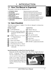
...parallel data processing and compression, precise pixel interpolation, full 2D hardware acceleration, and motion video acceleration. FEATURES 2.1 The ASUS TUSL2 The ASUS TUSL2 motherboard is carefully designed for high performance, component level interconnect targeted at 3D graphical applications using a 1X, 2X, or 4X... Keyboard Wake-Up, and BIOS Wake-Up. • Smart Card Reader Compatible: PC/SC compliant Smart Card Reader connectivity. 8 ASUS TUSL2 User's Manual two USB controllers for a total of 4 USB ports. • Intel® Accelerated Hub Architecture: Features a ...
...parallel data processing and compression, precise pixel interpolation, full 2D hardware acceleration, and motion video acceleration. FEATURES 2.1 The ASUS TUSL2 The ASUS TUSL2 motherboard is carefully designed for high performance, component level interconnect targeted at 3D graphical applications using a 1X, 2X, or 4X... Keyboard Wake-Up, and BIOS Wake-Up. • Smart Card Reader Compatible: PC/SC compliant Smart Card Reader connectivity. 8 ASUS TUSL2 User's Manual two USB controllers for a total of 4 USB ports. • Intel® Accelerated Hub Architecture: Features a ...

TUSL2 User Manual
Page 9
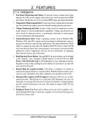
...motherboard. With an ASUS iPanel, you can monitor your computer system's vital components. • LCD/TV Output: The Intel DVO (Digital Video Out) interface can support Bus Master PCI cards, such as SCSI or LAN cards. (PCI supports up when there is removed and through BIOS setup. ASUS TUSL2... User's Manual 9 FEATURES • ASUS JumperFree™ Mode: JumperFree Mode supplies precise overclocking of CPU external (FSB) frequency in firmware-based virus protection, and...
...motherboard. With an ASUS iPanel, you can monitor your computer system's vital components. • LCD/TV Output: The Intel DVO (Digital Video Out) interface can support Bus Master PCI cards, such as SCSI or LAN cards. (PCI supports up when there is removed and through BIOS setup. ASUS TUSL2... User's Manual 9 FEATURES • ASUS JumperFree™ Mode: JumperFree Mode supplies precise overclocking of CPU external (FSB) frequency in firmware-based virus protection, and...

TUSL2 User Manual
Page 10
...devices in the OS, PCs can be ready around the clock, yet satisfy all ASUS smart series motherboards. Color-coded connectors and descriptive icons make identification easy. 10 ASUS TUSL2 User's Manual Data "striping," or RAID 0, improves speed performance as the protocol optimizes... PCI: Concurrent PCI allows multiple PCI transfers from PCI master buses to memory and processor. • SDRAM Optimized Performance: This motherboard supports PC133-compliant Synchronous Dynamic Random Access Memory (SDRAM), which increases the data transfer rate to 1066MB/s max. • ACPI...
...devices in the OS, PCs can be ready around the clock, yet satisfy all ASUS smart series motherboards. Color-coded connectors and descriptive icons make identification easy. 10 ASUS TUSL2 User's Manual Data "striping," or RAID 0, improves speed performance as the protocol optimizes... PCI: Concurrent PCI allows multiple PCI transfers from PCI master buses to memory and processor. • SDRAM Optimized Performance: This motherboard supports PC133-compliant Synchronous Dynamic Random Access Memory (SDRAM), which increases the data transfer rate to 1066MB/s max. • ACPI...
TUSL2 User Manual
Page 11
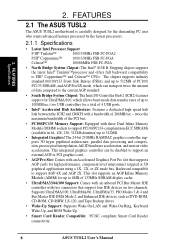
... Dual Function Power Button: Through BIOS, the power button can be monitored for future processors, so monitoring is necessary to critical motherboard components. FEATURES Intelligence 2. Voltage specifications are more than 4 seconds will warn the user before the system resources are monitored to ensure... (requires ACPI OS support): Message LEDs now act as Windows ME, Windows 2000, and OS/2, require much more information) button. ASUS TUSL2 User's Manual 11 All the fans are set for its normal RPM range and alarm thresholds. • Temperature Monitoring andAlert: To prevent...
... Dual Function Power Button: Through BIOS, the power button can be monitored for future processors, so monitoring is necessary to critical motherboard components. FEATURES Intelligence 2. Voltage specifications are more than 4 seconds will warn the user before the system resources are monitored to ensure... (requires ACPI OS support): Message LEDs now act as Windows ME, Windows 2000, and OS/2, require much more information) button. ASUS TUSL2 User's Manual 11 All the fans are set for its normal RPM range and alarm thresholds. • Temperature Monitoring andAlert: To prevent...
TUSL2 User Manual
Page 12
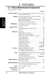
...Connectors (ATA100 Support 5 2 IDE Connectors (ATA100 / RAID 0 or 1 Support 7 1 Smart Card Connector 12 1 Serial COM2 Header 18 1 ASUS iPanel Connector 10 1 Parallel Port Connector 28 1 Serial COM1 Port Connector Bottom) 29 2 USB Port Connectors 30 1 PS/2 Mouse Connector Top) 31...Voltage Monitoring (integrated in ASUS ASIC) ....... 17 3 Fan Power and Speed Monitoring Connectors Power ATX Power Supply Connector 1 Special Feature Onboard LED 20 Form Factor ATX 12 ASUS TUSL2 User's Manual FEATURES MB Components 2. FEATURES 2.2 TUSL2 Motherboard Components See opposite page ...
...Connectors (ATA100 Support 5 2 IDE Connectors (ATA100 / RAID 0 or 1 Support 7 1 Smart Card Connector 12 1 Serial COM2 Header 18 1 ASUS iPanel Connector 10 1 Parallel Port Connector 28 1 Serial COM1 Port Connector Bottom) 29 2 USB Port Connectors 30 1 PS/2 Mouse Connector Top) 31...Voltage Monitoring (integrated in ASUS ASIC) ....... 17 3 Fan Power and Speed Monitoring Connectors Power ATX Power Supply Connector 1 Special Feature Onboard LED 20 Form Factor ATX 12 ASUS TUSL2 User's Manual FEATURES MB Components 2. FEATURES 2.2 TUSL2 Motherboard Components See opposite page ...

TUSL2 User Manual
Page 14
HARDWARE SETUP 3.1 TUSL2 Motherboard Layout PS/2KBMS T: Mouse B: Keyboard USB T: Port1 B: ...AUX CD AAPANEL MODEM HPHONE BCS1 BCS2 CMI8738 Audio Controller JTPWR PCI1 PCI2 WOL_CON PCI3 PLED2 PCI4 PCI5 TUSL2 PCI6 OC3 CNR_SLOT COM2 CR2032 3V Lithium Cell CMOS Power Intel I/O Controller Hub (ICH2) CLRTC &#...Controller Firmware Hub (FWH) ASUS ASIC with Hardware Monitor JP3 JEN JP4 ACHA WOR Super I/O CHA_FAN USBPWR23 USB23 AFPANEL IDELED SMARTCARD PANEL Grayed components are optional at the time of purchase. 14 ASUS TUSL2 User's Manual 3. H/W SETUP Motherboard Layout 3.
HARDWARE SETUP 3.1 TUSL2 Motherboard Layout PS/2KBMS T: Mouse B: Keyboard USB T: Port1 B: ...AUX CD AAPANEL MODEM HPHONE BCS1 BCS2 CMI8738 Audio Controller JTPWR PCI1 PCI2 WOL_CON PCI3 PLED2 PCI4 PCI5 TUSL2 PCI6 OC3 CNR_SLOT COM2 CR2032 3V Lithium Cell CMOS Power Intel I/O Controller Hub (ICH2) CLRTC &#...Controller Firmware Hub (FWH) ASUS ASIC with Hardware Monitor JP3 JEN JP4 ACHA WOR Super I/O CHA_FAN USBPWR23 USB23 AFPANEL IDELED SMARTCARD PANEL Grayed components are optional at the time of purchase. 14 ASUS TUSL2 User's Manual 3. H/W SETUP Motherboard Layout 3.

TUSL2 User Manual
Page 15
H/W SETUP Layout Contents 3. 3. HARDWARE SETUP 3.2 Layout Contents Motherboard Settings 1) JEN 2) JP3 3) JP4 4) USBPWR01 USBPWR23 5) OC3 6) KBPWR 7) DSW 8) VIO 9) BCS p.18 JumperFree™ Mode (Enable/Disable) p.19 ATA100 / RAID 0/1 (Enable) p.19 Onboard IDE (Enable/... Connectors (Four 4-pins) (optional) 14) EARPHONE p.38 Headphone True-Level Line Out Header (3 pins) 15) MIC2 p.39 Internal Microphone Connector (3 pins) 16) AFPANEL/IR_CON p.39 ASUS iPanel Connector (12-1 pins) 17) AAPANEL p.40 ASUS iPanel Audio Connector (12-1 pins) ASUS TUSL2 User's Manual 15
H/W SETUP Layout Contents 3. 3. HARDWARE SETUP 3.2 Layout Contents Motherboard Settings 1) JEN 2) JP3 3) JP4 4) USBPWR01 USBPWR23 5) OC3 6) KBPWR 7) DSW 8) VIO 9) BCS p.18 JumperFree™ Mode (Enable/Disable) p.19 ATA100 / RAID 0/1 (Enable) p.19 Onboard IDE (Enable/... Connectors (Four 4-pins) (optional) 14) EARPHONE p.38 Headphone True-Level Line Out Header (3 pins) 15) MIC2 p.39 Internal Microphone Connector (3 pins) 16) AFPANEL/IR_CON p.39 ASUS iPanel Connector (12-1 pins) 17) AAPANEL p.40 ASUS iPanel Audio Connector (12-1 pins) ASUS TUSL2 User's Manual 15
TUSL2 User Manual
Page 17
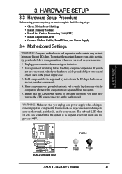
...component whenever the components are separated from static electricity, you should follow some precautions whenever you must complete the following steps: • Check Motherboard Settings • Install Memory Modules • Install the Central Processing Unit (CPU) • Install Expansion Cards • Connect Ribbon ...is in or remove the ATX power connector on the motherboard. The onboard LED when lit acts as the power supply case. 3. COM1 PLED2 ® TUSL2 TUSL2 Onboard LED ON Standby Power OFF Powered Off ASUS TUSL2 User's Manual 17 If you plug in suspend or ...
...component whenever the components are separated from static electricity, you should follow some precautions whenever you must complete the following steps: • Check Motherboard Settings • Install Memory Modules • Install the Central Processing Unit (CPU) • Install Expansion Cards • Connect Ribbon ...is in or remove the ATX power connector on the motherboard. The onboard LED when lit acts as the power supply case. 3. COM1 PLED2 ® TUSL2 TUSL2 Onboard LED ON Standby Power OFF Powered Off ASUS TUSL2 User's Manual 17 If you plug in suspend or ...

TUSL2 User Manual
Page 18
... Selection 5. Frequency Selection 4. H/W SETUP Motherboard Settings 1) JumperFree™ Mode (JEN) This jumper allows you to OFF. The example below shows all dip switches must be made through jumpers or DIP switches. DSW COM1 ON 12345 ® TUSL2 TUSL2 DIP Switches ON OFF 1. When using .... Setting JEN Disable (Jumper) [1-2] Enable (JumperFree) [2-3] (default) DSW COM1 ON 12345 JEN 12 ® TUSL2 Disable Jumper Mode TUSL2 JumperFree™ Mode Setting OFF JEN 23 Enable JumperFree Mode (Default) 18 ASUS TUSL2 User's Manual Frequency Selection. 3.
... Selection 5. Frequency Selection 4. H/W SETUP Motherboard Settings 1) JumperFree™ Mode (JEN) This jumper allows you to OFF. The example below shows all dip switches must be made through jumpers or DIP switches. DSW COM1 ON 12345 ® TUSL2 TUSL2 DIP Switches ON OFF 1. When using .... Setting JEN Disable (Jumper) [1-2] Enable (JumperFree) [2-3] (default) DSW COM1 ON 12345 JEN 12 ® TUSL2 Disable Jumper Mode TUSL2 JumperFree™ Mode Setting OFF JEN 23 Enable JumperFree Mode (Default) 18 ASUS TUSL2 User's Manual Frequency Selection. 3.

TUSL2 User Manual
Page 19
...) 3) Onboard IDE ( JP4) These jumpers enable or disable the IDE function of the motherboard. Setting JP4 Enable Onboard IDE [1-2] (default) Disable Onboard IDE [3-4] COM1 ® TUSL2 TUSL2 Onboard IDE Selection JP4 12 23 ENABLE Onboard IDE DISABLE Onboard IDE (Default) ASUS TUSL2 User's Manual 19 The default setting is ATA100. 3. Under normal circumstances, these jumpers...
...) 3) Onboard IDE ( JP4) These jumpers enable or disable the IDE function of the motherboard. Setting JP4 Enable Onboard IDE [1-2] (default) Disable Onboard IDE [3-4] COM1 ® TUSL2 TUSL2 Onboard IDE Selection JP4 12 23 ENABLE Onboard IDE DISABLE Onboard IDE (Default) ASUS TUSL2 User's Manual 19 The default setting is ATA100. 3. Under normal circumstances, these jumpers...

TUSL2 User Manual
Page 22
....2MHz 100.3MHz 103.0MHz 100.30MHz AGP 66.8MHz 66.8MHz 68.7MHz 66.85MHz ® ON 12345 ON 12345 ON 12345 ON 12345 TUSL2 TUSL2 CPU External CPU DRAM Clock (BUS) Frequency AGP Selection 140MHz 133.70MHz 105MHz 133.70MHz 70MHz 66.85MHz 140MHz (JumperFree Mode) 140MHz 70MHz NOTE: If... have no effect. 3. If the Frequency Multiple is enabled, use CPU Core:Bus Freq. Multiple in BIOS Setup). NOTE: Only selected switches are illustrated. H/W SETUP Motherboard Settings 22 ASUS TUSL2 User's Manual This allows the selection of these switches (see next page.
....2MHz 100.3MHz 103.0MHz 100.30MHz AGP 66.8MHz 66.8MHz 68.7MHz 66.85MHz ® ON 12345 ON 12345 ON 12345 ON 12345 TUSL2 TUSL2 CPU External CPU DRAM Clock (BUS) Frequency AGP Selection 140MHz 133.70MHz 105MHz 133.70MHz 70MHz 66.85MHz 140MHz (JumperFree Mode) 140MHz 70MHz NOTE: If... have no effect. 3. If the Frequency Multiple is enabled, use CPU Core:Bus Freq. Multiple in BIOS Setup). NOTE: Only selected switches are illustrated. H/W SETUP Motherboard Settings 22 ASUS TUSL2 User's Manual This allows the selection of these switches (see next page.

TUSL2 User Manual
Page 23
...even shortening the life of the processor. HARDWARE SETUP External Frequency Table The following table is for use by experienced motherboard installers only. CPU:DRAM CPU Ratio (MHz) 66:100 66:100 66:100 66:100 66:100 66:... [O N ] [O N ] [O FF] [O FF] [O N ] [O FF] [O N ] [O FF] [O N ] [O FF] [O N ] [O FF] [O N ] [O FF] [O N ] [O FF] [O N ] [O FF] [O N ] [O FF] [O N ] [O FF] [O N ] [O FF] [O N ] [O FF] [O N ] [O FF] [O N ] [O FF] [O N ] [O FF] [O N ] [O FF] [O N ] [O FF] For updated processor settings, visit ASUS's web site (see ASUS CONTACT INFORMATION) ASUS TUSL2 User's Manual 23
...even shortening the life of the processor. HARDWARE SETUP External Frequency Table The following table is for use by experienced motherboard installers only. CPU:DRAM CPU Ratio (MHz) 66:100 66:100 66:100 66:100 66:100 66:... [O N ] [O N ] [O FF] [O FF] [O N ] [O FF] [O N ] [O FF] [O N ] [O FF] [O N ] [O FF] [O N ] [O FF] [O N ] [O FF] [O N ] [O FF] [O N ] [O FF] [O N ] [O FF] [O N ] [O FF] [O N ] [O FF] [O N ] [O FF] [O N ] [O FF] [O N ] [O FF] [O N ] [O FF] [O N ] [O FF] For updated processor settings, visit ASUS's web site (see ASUS CONTACT INFORMATION) ASUS TUSL2 User's Manual 23

TUSL2 User Manual
Page 24
... the Line-In, Line-Out, Mic female sockets. COM1 ® TUSL2 TUSL2 Bass Center Setting BCS 21 32 type 1 Bass (CENTER/BASS) type 2 Bass (BASS/CENTER) (Default) 24 ASUS TUSL2 User's Manual Make sure a test is highly recommended that you to ... V [2-3] (default) 3.60 V [3-4] VIO COM1 ® TUSL2 2 1 3.30 V 4 3 3 2 3.40 V 3.60 V (Default) TUSL2 VIO Setting WARNING! Using a higher voltage may help reroute signals among the internal leads in conjunction with the C-Media PCI Audio Driver and to the DRAM, chipset, AGP, and PCI. H/W SETUP Motherboard Settings 3.
... the Line-In, Line-Out, Mic female sockets. COM1 ® TUSL2 TUSL2 Bass Center Setting BCS 21 32 type 1 Bass (CENTER/BASS) type 2 Bass (BASS/CENTER) (Default) 24 ASUS TUSL2 User's Manual Make sure a test is highly recommended that you to ... V [2-3] (default) 3.60 V [3-4] VIO COM1 ® TUSL2 2 1 3.30 V 4 3 3 2 3.40 V 3.60 V (Default) TUSL2 VIO Setting WARNING! Using a higher voltage may help reroute signals among the internal leads in conjunction with the C-Media PCI Audio Driver and to the DRAM, chipset, AGP, and PCI. H/W SETUP Motherboard Settings 3.

TUSL2 User Manual
Page 25
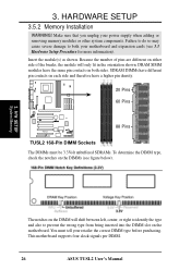
... vs. Install memory in 32, 64, 128, 256, 512MB. Otherwise, the system may hang during startup. 3.5.1 General DIMM Notes • ASUS motherboards support SPD (Serial Presence Detect) DIMMs. This is the memory of the DIMM takes up one row on bootup screen. • Single-sided..., 128, 256, 512MB x1 Total System Memory (Max 512MB) = NOTE: Make sure the total installed memory does not exceeds 512MB. ASUS TUSL2 User's Manual 25 This motherboard uses only Dual Inline Memory Modules (DIMMs). One side (with memory chips) of choice for 3.3Volt (power level) unbuffered Synchronous Dynamic...
... vs. Install memory in 32, 64, 128, 256, 512MB. Otherwise, the system may hang during startup. 3.5.1 General DIMM Notes • ASUS motherboards support SPD (Serial Presence Detect) DIMMs. This is the memory of the DIMM takes up one row on bootup screen. • Single-sided..., 128, 256, 512MB x1 Total System Memory (Max 512MB) = NOTE: Make sure the total installed memory does not exceeds 512MB. ASUS TUSL2 User's Manual 25 This motherboard uses only Dual Inline Memory Modules (DIMMs). One side (with memory chips) of choice for 3.3Volt (power level) unbuffered Synchronous Dynamic...
TUSL2 User Manual
Page 26
... be 3.3Volt unbuffered SDRAMs. To determine the DIMM type, check the notches on both your motherboard and expansion cards (see figure below). 3. HARDWARE SETUP 3.5.2 Memory Installation WARNING! COM1 20 Pins 60 Pins ® TUSL2 88 Pins TUSL2 168-Pin DIMM Sockets The DIMMs must tell your power supply when adding or removing memory... retailer the correct DIMM type before purchasing. Because the number of pins are different on the DIMM will only fit in the orientation shown. This motherboard supports four clock signals per DIMM. 26 ASUS TUSL2 User's Manual
... be 3.3Volt unbuffered SDRAMs. To determine the DIMM type, check the notches on both your motherboard and expansion cards (see figure below). 3. HARDWARE SETUP 3.5.2 Memory Installation WARNING! COM1 20 Pins 60 Pins ® TUSL2 88 Pins TUSL2 168-Pin DIMM Sockets The DIMMs must tell your power supply when adding or removing memory... retailer the correct DIMM type before purchasing. Because the number of pins are different on the DIMM will only fit in the orientation shown. This motherboard supports four clock signals per DIMM. 26 ASUS TUSL2 User's Manual

TUSL2 User Manual
Page 27
... ASUS TUSL2 User's Manual 27 H/W SETUP System Memory 3. Then lift the lever upwards. Socket 370 processors provide internal thermal sensing: a socket mounted thermal resistor is available only on unlocked processors) for CPU installation. HARDWARE SETUP 3.6 Central Processing Unit (CPU) The motherboard ...frequency multiple setting is not needed. COM1 Coppermine/ Celeron Gold Arrow ® TUSL2 Tualatin TUSL2 Socket 370 Gold Arrow 1. CAUTION! NOTE: Do not forget to scrape the motherboard surface when mounting a clamp-style processor fan, or else damage may occur!...
... ASUS TUSL2 User's Manual 27 H/W SETUP System Memory 3. Then lift the lever upwards. Socket 370 processors provide internal thermal sensing: a socket mounted thermal resistor is available only on unlocked processors) for CPU installation. HARDWARE SETUP 3.6 Central Processing Unit (CPU) The motherboard ...frequency multiple setting is not needed. COM1 Coppermine/ Celeron Gold Arrow ® TUSL2 Tualatin TUSL2 Socket 370 Gold Arrow 1. CAUTION! NOTE: Do not forget to scrape the motherboard surface when mounting a clamp-style processor fan, or else damage may occur!...


