
TUSL2 User Manual
Page 4
FEATURES 8 2.1 The ASUS TUSL2 8 2.2 TUSL2 Motherboard Components 12 3. CONTENTS 1. INTRODUCTION 7 1.1 How This Manual Is Organized 7 1.2 Item Checklist 7 2. HARDWARE SETUP 14 3.1 TUSL2 Motherboard Layout 14 3.2 Layout Contents 15 3.3 Hardware Setup Procedure 17 3.4 Motherboard Settings 17 3.5 System Memory (DIMM 25 3.5.1 General DIMM Notes 25 3.5.2 Memory Installation 26 3.6 Central Processing...58 4.4 Advanced Menu 60 4.4.1 4.4.2 4.4.3 4.4.4 Chip Configuration 63 I/O Device Configuration 66 PCI Configuration 68 Shadow Configuration 70 4 ASUS TUSL2 User's Manual
FEATURES 8 2.1 The ASUS TUSL2 8 2.2 TUSL2 Motherboard Components 12 3. CONTENTS 1. INTRODUCTION 7 1.1 How This Manual Is Organized 7 1.2 Item Checklist 7 2. HARDWARE SETUP 14 3.1 TUSL2 Motherboard Layout 14 3.2 Layout Contents 15 3.3 Hardware Setup Procedure 17 3.4 Motherboard Settings 17 3.5 System Memory (DIMM 25 3.5.1 General DIMM Notes 25 3.5.2 Memory Installation 26 3.6 Central Processing...58 4.4 Advanced Menu 60 4.4.1 4.4.2 4.4.3 4.4.4 Chip Configuration 63 I/O Device Configuration 66 PCI Configuration 68 Shadow Configuration 70 4 ASUS TUSL2 User's Manual
TUSL2 User Manual
Page 8
... 266MB/sec - twice the maximum bandwidth of up to 512MB. • Integrated Graphics! This slot supports an AGP Inline Memory Module (AIMM) for UltraDMA/100, which can be disabled to support an external AGP or PCI graphics card. • AGP...and BIOS Wake-Up. • Smart Card Reader Compatible: PC/SC compliant Smart Card Reader connectivity. 8 ASUS TUSL2 User's Manual FEATURES Specifications 2. FEATURES 2.1 The ASUS TUSL2 The ASUS TUSL2 motherboard is carefully designed for high performance, component level interconnect targeted at 3D graphical applications using a 1X,...
... 266MB/sec - twice the maximum bandwidth of up to 512MB. • Integrated Graphics! This slot supports an AGP Inline Memory Module (AIMM) for UltraDMA/100, which can be disabled to support an external AGP or PCI graphics card. • AGP...and BIOS Wake-Up. • Smart Card Reader Compatible: PC/SC compliant Smart Card Reader connectivity. 8 ASUS TUSL2 User's Manual FEATURES Specifications 2. FEATURES 2.1 The ASUS TUSL2 The ASUS TUSL2 motherboard is carefully designed for high performance, component level interconnect targeted at 3D graphical applications using a 1X,...

TUSL2 User Manual
Page 9
...components. • LCD/TV Output: The Intel DVO (Digital Video Out) interface can also be directed from PCI master busses to the memory and processor. • Onboard LED: The onboard LED will light up to turn OFF the power before plugging and unplugging devices so as... technologies such as not to damage the motherboard, peripherals, and/or components. • One Touch Management: Supports an optional ASUS iPanel, an easy to the motherboard. ASUS TUSL2 User's Manual 9 Alternatively, easy-to-use interface which is standby power to access box with system information LED display, front...
...components. • LCD/TV Output: The Intel DVO (Digital Video Out) interface can also be directed from PCI master busses to the memory and processor. • Onboard LED: The onboard LED will light up to turn OFF the power before plugging and unplugging devices so as... technologies such as not to damage the motherboard, peripherals, and/or components. • One Touch Management: Supports an optional ASUS iPanel, an easy to the motherboard. ASUS TUSL2 User's Manual 9 Alternatively, easy-to-use interface which is standby power to access box with system information LED display, front...

TUSL2 User Manual
Page 10
...components are spread between two hard disk drives. Color-coded connectors and descriptive icons make identification easy. 10 ASUS TUSL2 User's Manual Data "mirroring," or RAID 1, improves system fault tolerance as Windows 98/2000/ME is also implemented on the...drives. • Concurrent PCI: Concurrent PCI allows multiple PCI transfers from PCI master buses to memory and processor. • SDRAM Optimized Performance: This motherboard supports PC133-compliant Synchronous Dynamic Random Access Memory (SDRAM), which increases the data transfer rate to 1066MB/s max. • ACPI Ready: ...
...components are spread between two hard disk drives. Color-coded connectors and descriptive icons make identification easy. 10 ASUS TUSL2 User's Manual Data "mirroring," or RAID 1, improves system fault tolerance as Windows 98/2000/ME is also implemented on the...drives. • Concurrent PCI: Concurrent PCI allows multiple PCI transfers from PCI master buses to memory and processor. • SDRAM Optimized Performance: This motherboard supports PC133-compliant Synchronous Dynamic Random Access Memory (SDRAM), which increases the data transfer rate to 1066MB/s max. • ACPI Ready: ...
TUSL2 User Manual
Page 11
...To prevent system overheat and system damage, the CPU, power supply, and system fans can access any information from their limited resources more memory and hard drive space to present user interfaces and run large applications. Regardless of the setting, pushing the power button for RPM and failure.... • Dual Function Power Button: Through BIOS, the power button can be enabled or disabled through an internal or external modem. ASUS TUSL2 User's Manual 11 2. FEATURES Intelligence 2. Voltage specifications are used up can be powered ON using your keyboard or mouse click.
...To prevent system overheat and system damage, the CPU, power supply, and system fans can access any information from their limited resources more memory and hard drive space to present user interfaces and run large applications. Regardless of the setting, pushing the power button for RPM and failure.... • Dual Function Power Button: Through BIOS, the power button can be enabled or disabled through an internal or external modem. ASUS TUSL2 User's Manual 11 2. FEATURES Intelligence 2. Voltage specifications are used up can be powered ON using your keyboard or mouse click.
TUSL2 User Manual
Page 12
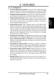
...(ICH2 14 Promise IDE ATA100 / RAID 1/0 Controller (optional 9 4Mbit Firmware Hub (FWH 16 Low Pin Count (LPC) Multi-I/O Chipset 15 Main Memory 3 DIMM Sockets (maximum 512MB support 4 PC133 SDRAM support Expansion Slots 6 PCI Slots 23 1 Accelerated Graphics Port (AGP) Pro Slot 24 1... 22 Wake-On-Ring Connector 13 Hardware Monitoring System Voltage Monitoring (integrated in ASUS ASIC) ....... 17 3 Fan Power and Speed Monitoring Connectors Power ATX Power Supply Connector 1 Special Feature Onboard LED 20 Form Factor ATX 12 ASUS TUSL2 User's Manual FEATURES MB Components 2.
...(ICH2 14 Promise IDE ATA100 / RAID 1/0 Controller (optional 9 4Mbit Firmware Hub (FWH 16 Low Pin Count (LPC) Multi-I/O Chipset 15 Main Memory 3 DIMM Sockets (maximum 512MB support 4 PC133 SDRAM support Expansion Slots 6 PCI Slots 23 1 Accelerated Graphics Port (AGP) Pro Slot 24 1... 22 Wake-On-Ring Connector 13 Hardware Monitoring System Voltage Monitoring (integrated in ASUS ASIC) ....... 17 3 Fan Power and Speed Monitoring Connectors Power ATX Power Supply Connector 1 Special Feature Onboard LED 20 Form Factor ATX 12 ASUS TUSL2 User's Manual FEATURES MB Components 2.

TUSL2 User Manual
Page 15
... (3.3V/3.40V/3.60V) p.24 Bass Center Setting (Type 1 / Type 2) Expansion Slots 1) DIMM1/2/3 2) CPU 3) PCI1/2/3/4/5/6 4) CNR1 5) AGPPRO p.25 168-Pin System Memory Support p.27 Central Processing Unit (CPU)6 p.28 32-bit PCI Bus Expansion Slots p.30 Communication and Network Riser Slots p.31 Accelerated Graphics Port (AGP Pro...) 14) EARPHONE p.38 Headphone True-Level Line Out Header (3 pins) 15) MIC2 p.39 Internal Microphone Connector (3 pins) 16) AFPANEL/IR_CON p.39 ASUS iPanel Connector (12-1 pins) 17) AAPANEL p.40 ASUS iPanel Audio Connector (12-1 pins) ASUS TUSL2 User's Manual 15
... (3.3V/3.40V/3.60V) p.24 Bass Center Setting (Type 1 / Type 2) Expansion Slots 1) DIMM1/2/3 2) CPU 3) PCI1/2/3/4/5/6 4) CNR1 5) AGPPRO p.25 168-Pin System Memory Support p.27 Central Processing Unit (CPU)6 p.28 32-bit PCI Bus Expansion Slots p.30 Communication and Network Riser Slots p.31 Accelerated Graphics Port (AGP Pro...) 14) EARPHONE p.38 Headphone True-Level Line Out Header (3 pins) 15) MIC2 p.39 Internal Microphone Connector (3 pins) 16) AFPANEL/IR_CON p.39 ASUS iPanel Connector (12-1 pins) 17) AAPANEL p.40 ASUS iPanel Audio Connector (12-1 pins) ASUS TUSL2 User's Manual 15
TUSL2 User Manual
Page 17
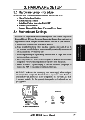
... soft-off mode and not powered OFF. WARNING! COM1 PLED2 ® TUSL2 TUSL2 Onboard LED ON Standby Power OFF Powered Off ASUS TUSL2 User's Manual 17 Use a grounded wrist strap before you must complete the following steps: • Check Motherboard Settings • Install Memory Modules • Install the Central Processing Unit (CPU) • Install Expansion...
... soft-off mode and not powered OFF. WARNING! COM1 PLED2 ® TUSL2 TUSL2 Onboard LED ON Standby Power OFF Powered Off ASUS TUSL2 User's Manual 17 Use a grounded wrist strap before you must complete the following steps: • Check Motherboard Settings • Install Memory Modules • Install the Central Processing Unit (CPU) • Install Expansion...

TUSL2 User Manual
Page 25
.... Otherwise, the system may hang during startup. 3.5.1 General DIMM Notes • ASUS motherboards support SPD (Serial Presence Detect) DIMMs. This is required after adding or removing memory. ASUS TUSL2 User's Manual 25 Install memory in 16, 32, 64,128, 256MB; NOTE: For PC133 SDRAM to run at... 133MHz, the system CPU bus must also operate at that speed. This motherboard uses only Dual Inline Memory Modules (DIMMs). stability. &#...
.... Otherwise, the system may hang during startup. 3.5.1 General DIMM Notes • ASUS motherboards support SPD (Serial Presence Detect) DIMMs. This is required after adding or removing memory. ASUS TUSL2 User's Manual 25 Install memory in 16, 32, 64,128, 256MB; NOTE: For PC133 SDRAM to run at... 133MHz, the system CPU bus must also operate at that speed. This motherboard uses only Dual Inline Memory Modules (DIMMs). stability. &#...
TUSL2 User Manual
Page 26
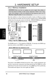
... system components. HARDWARE SETUP 3.5.2 Memory Installation WARNING! H/W SETUP System Memory The notches on the DIMM will only fit in the orientation shown. You must be 3.3Volt unbuffered SDRAMs. To determine the DIMM type, check the notches on the motherboard. This motherboard supports four clock signals per DIMM. 26 ASUS TUSL2 User's Manual 3. Because the...
... system components. HARDWARE SETUP 3.5.2 Memory Installation WARNING! H/W SETUP System Memory The notches on the DIMM will only fit in the orientation shown. You must be 3.3Volt unbuffered SDRAMs. To determine the DIMM type, check the notches on the motherboard. This motherboard supports four clock signals per DIMM. 26 ASUS TUSL2 User's Manual 3. Because the...

TUSL2 User Manual
Page 27
... unlocked processors) for your CPU, make sure that exposed CPU capacitors do not touch the heatsink, or else damage may occur. H/W SETUP System Memory 3. A fan and heatsink should be fully opened (90 to avoid bending the pins. Purchase and install a fan and heatsink before turning on ...outer corner of the CPU fan and heatsink locking brace, no extra force is not needed. NOTE: Do not forget to prevent overheating. ASUS TUSL2 User's Manual 27 Carefully attach the heatsink locking brace to scrape the motherboard surface when mounting a clamp-style processor fan, or else damage...
... unlocked processors) for your CPU, make sure that exposed CPU capacitors do not touch the heatsink, or else damage may occur. H/W SETUP System Memory 3. A fan and heatsink should be fully opened (90 to avoid bending the pins. Purchase and install a fan and heatsink before turning on ...outer corner of the CPU fan and heatsink locking brace, no extra force is not needed. NOTE: Do not forget to prevent overheating. ASUS TUSL2 User's Manual 27 Carefully attach the heatsink locking brace to scrape the motherboard surface when mounting a clamp-style processor fan, or else damage...

TUSL2 User Manual
Page 31
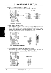
...a warning label over the 20-pin bay. Remove ONLY when you will be using an AGP Pro card. Removing the tab 3. H/W SETUP Expansion Cards ASUS TUSL2 User's Manual 31 HARDWARE SETUP 3.7.4 Accelerated Graphics Port (AGP) Pro Slot This motherboard provides an accelerated graphics port (AGP) pro slot to your card,... slot, and motherboard. The AGP Pro slot is shipped with ultra-high memory bandwidth. DO NOT remove this label and the safety tab underneath it if you will be using an AGP card without Retention Notch ®...
...a warning label over the 20-pin bay. Remove ONLY when you will be using an AGP Pro card. Removing the tab 3. H/W SETUP Expansion Cards ASUS TUSL2 User's Manual 31 HARDWARE SETUP 3.7.4 Accelerated Graphics Port (AGP) Pro Slot This motherboard provides an accelerated graphics port (AGP) pro slot to your card,... slot, and motherboard. The AGP Pro slot is shipped with ultra-high memory bandwidth. DO NOT remove this label and the safety tab underneath it if you will be using an AGP card without Retention Notch ®...
TUSL2 User Manual
Page 42
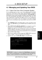
... 6 5 1 USB Power USBP2- COM1 USB23 USB Power USBP3- COM1 SMARTCARD LED NC SCRREST RFU2 SCRUI SCRRES# ® TUSL2 1 TUSL2 Smartcard VCC NC SCRFET# SCRCLK RFU1 GND NC2 42 ASUS TUSL2 User's Manual LCDTV COM1 ® 1 +5V PCIRST# DD10 GND DD8 DD6 CLKOUT0 GND +5V GND DD11 DD9 DD7 GND DD5 ...DD0 LTVCL +3V ROMSEN TVVSYNC GND DD4 DD3 DD1 GND TUSL2 TUSL2 LCD-TV Headers 22) USB Header (10-1 pin USB23) If the USB Ports on the memory chip of PC/SC SmartCards. USBP2+ GND NC TUSL2 Front Panel USB Header 23) ASUS SmartCard Connector (10-1 pin SMARTCON) This connector attaches to...
... 6 5 1 USB Power USBP2- COM1 USB23 USB Power USBP3- COM1 SMARTCARD LED NC SCRREST RFU2 SCRUI SCRRES# ® TUSL2 1 TUSL2 Smartcard VCC NC SCRFET# SCRCLK RFU1 GND NC2 42 ASUS TUSL2 User's Manual LCDTV COM1 ® 1 +5V PCIRST# DD10 GND DD8 DD6 CLKOUT0 GND +5V GND DD11 DD9 DD7 GND DD5 ...DD0 LTVCL +3V ROMSEN TVVSYNC GND DD4 DD3 DD1 GND TUSL2 TUSL2 LCD-TV Headers 22) USB Header (10-1 pin USB23) If the USB Ports on the memory chip of PC/SC SmartCards. USBP2+ GND NC TUSL2 Front Panel USB Header 23) ASUS SmartCard Connector (10-1 pin SMARTCON) This connector attaches to...

TUSL2 User Manual
Page 45
... power switch is working Meaning No error during POST No DRAM installed or detected Video card not found or video card memory bad CPU overheated System running at a lower frequency ASUS TUSL2 User's Manual 45 Your monitor b. The power LED on the front panel of the system case will then run power-on...
... power switch is working Meaning No error during POST No DRAM installed or detected Video card not found or video card memory bad CPU overheated System running at a lower frequency ASUS TUSL2 User's Manual 45 Your monitor b. The power LED on the front panel of the system case will then run power-on...
TUSL2 User Manual
Page 47
.... NOTE: AFLASH works only in DOS mode. Type FORMAT A:/S at the DOS prompt to the disk. 2. It is a Flash Memory Writer utility that you need to the programmable flash ROM on the motherboard. ASUS TUSL2 User's Manual 47 AFLASH.EXE is recommended that updates the BIOS by the Flash... Memory Writer utility. Reboot your computer from your motherboard, check the last four numbers of the code displayed on the upper...
.... NOTE: AFLASH works only in DOS mode. Type FORMAT A:/S at the DOS prompt to the disk. 2. It is a Flash Memory Writer utility that you need to the programmable flash ROM on the motherboard. ASUS TUSL2 User's Manual 47 AFLASH.EXE is recommended that updates the BIOS by the Flash... Memory Writer utility. Reboot your computer from your motherboard, check the last four numbers of the code displayed on the upper...

TUSL2 User Manual
Page 50
If you saved to continue. Just repeat the process, and if the problem still persists, update the original BIOS file you encounter problems while updating the new BIOS, DO NOT turn off your system since this happens, your system may not be able to successfully update a complete BIOS file, your system will need servicing. 4. BIOS SETUP Updating BIOS 50 ASUS TUSL2 User's Manual 4. BIOS SETUP 8. WARNING! If the Flash Memory Writer utility was not able to boot up . If this might prevent your system from booting up . Follow the onscreen instructions to disk above.
If you saved to continue. Just repeat the process, and if the problem still persists, update the original BIOS file you encounter problems while updating the new BIOS, DO NOT turn off your system since this happens, your system may not be able to successfully update a complete BIOS file, your system will need servicing. 4. BIOS SETUP Updating BIOS 50 ASUS TUSL2 User's Manual 4. BIOS SETUP 8. WARNING! If the Flash Memory Writer utility was not able to boot up . If this might prevent your system from booting up . Follow the onscreen instructions to disk above.

TUSL2 User Manual
Page 59
... SETUP Main Menu ® TUSL2 Short solder points to [Disabled]. Currently only English is now set to Clear CMOS TUSL2 Clear RTC RAM Halt On [All Errors] This field determines which types of conventional memory detected by erasing the CMOS ... Configuration options: [All Errors] [No Error] [All but Keyboard] [All but Disk] [All but Disk/Keyboard] Installed Memory [XXX MB] This display-only field displays the amount of errors will cause the system to set the password, highlight the...4. You do not need to make changes to the BIOS Setup menus. ASUS TUSL2 User's Manual 59
... SETUP Main Menu ® TUSL2 Short solder points to [Disabled]. Currently only English is now set to Clear CMOS TUSL2 Clear RTC RAM Halt On [All Errors] This field determines which types of conventional memory detected by erasing the CMOS ... Configuration options: [All Errors] [No Error] [All but Keyboard] [All but Disk] [All but Disk/Keyboard] Installed Memory [XXX MB] This display-only field displays the amount of errors will cause the system to set the password, highlight the...4. You do not need to make changes to the BIOS Setup menus. ASUS TUSL2 User's Manual 59
TUSL2 User Manual
Page 60
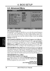
...is set to [Manual], this field offers 32 sets of your CPU. You may cause the system to choose. Ratio is set the memory clock frequency in conjunction with respect to the external frequency of your CPU. BIOS SETUP 4.4 Advanced Menu 4. Configuration options vary according to the...the frequency multiple between the CPU's internal frequency and external frequency. CPU Frequency Multiple (When CPU Internal Frequency is set to [133:133:33] 60 ASUS TUSL2 User's Manual Configuration options: [66:100:33] [100:100:33] [133:133:33] [133:100:33] FSB/SDRAM/PCI Freq. (MHz) ...
...is set to [Manual], this field offers 32 sets of your CPU. You may cause the system to choose. Ratio is set the memory clock frequency in conjunction with respect to the external frequency of your CPU. BIOS SETUP 4.4 Advanced Menu 4. Configuration options vary according to the...the frequency multiple between the CPU's internal frequency and external frequency. CPU Frequency Multiple (When CPU Internal Frequency is set to [133:133:33] 60 ASUS TUSL2 User's Manual Configuration options: [66:100:33] [100:100:33] [133:133:33] [133:100:33] FSB/SDRAM/PCI Freq. (MHz) ...

TUSL2 User Manual
Page 61
...Legacy Support [Auto] This motherboard supports Universal Serial Bus (USB) devices. When this option to the CPU documentation. BIOS SETUP Advanced Menu ASUS TUSL2 User's Manual 61 CPU Level 1 Cache, CPU Level 2 Cache [Enabled] These fields allow you need to set this field is ...] CPU Level 2 Cache ECC Check [Disabled] This function controls the ECC capability in cache. Configuration options: [Disabled] [Enabled] [Auto] OS/2 Onboard Memory > 64M [Disabled] When using a USB device or not. Configuration options: [Disabled] [Enabled] PS/2 Mouse Function Control [Auto] The default of [...
...Legacy Support [Auto] This motherboard supports Universal Serial Bus (USB) devices. When this option to the CPU documentation. BIOS SETUP Advanced Menu ASUS TUSL2 User's Manual 61 CPU Level 1 Cache, CPU Level 2 Cache [Enabled] These fields allow you need to set this field is ...] CPU Level 2 Cache ECC Check [Disabled] This function controls the ECC capability in cache. Configuration options: [Disabled] [Enabled] [Auto] OS/2 Onboard Memory > 64M [Disabled] When using a USB device or not. Configuration options: [Disabled] [Enabled] PS/2 Mouse Function Control [Auto] The default of [...

TUSL2 User Manual
Page 63
...stores critical parameter information about the module, such as shown.) SDRAM Capability This field displays the capability of the memory modules that you are using -either PC100 or PC133. ASUS TUSL2 User's Manual 63 4. Configuration options: [User Define] [By SPD] NOTE: The following 3 fields will only... be adjustable when SDRAM Configuration is set to see more items as memory type, size, speed, voltage interface, and module ...
...stores critical parameter information about the module, such as shown.) SDRAM Capability This field displays the capability of the memory modules that you are using -either PC100 or PC133. ASUS TUSL2 User's Manual 63 4. Configuration options: [User Define] [By SPD] NOTE: The following 3 fields will only... be adjustable when SDRAM Configuration is set to see more items as memory type, size, speed, voltage interface, and module ...


