

User Guide
Page 6
...the RAID 6-29 6.3.6 Setting the Boot array in the BIOS Setup Utility 6-31 6.4 Intel® Rapid Storage Technology enterprise (Windows 6-32 6.4.1 Creating a RAID set 6-33 6.4.2 Changing a Volume Type 6-35 6.4.3 Deleting a volume 6-36 6.4.4 Preferences 6-37 Chapter 7: Driver installation 7.1 RAID driver installation 7-2 7.1.1 Creating a RAID driver disk 7-2 7.1.2 Installing the RAID controller driver 7-3 7.2 Software drivers and utilities installation 7-13 7.3 Running the Support DVD 7-13 7.4 Installing the drivers and utilities 7-16 7.4.1 Using the ASUS InstAll application...
...the RAID 6-29 6.3.6 Setting the Boot array in the BIOS Setup Utility 6-31 6.4 Intel® Rapid Storage Technology enterprise (Windows 6-32 6.4.1 Creating a RAID set 6-33 6.4.2 Changing a Volume Type 6-35 6.4.3 Deleting a volume 6-36 6.4.4 Preferences 6-37 Chapter 7: Driver installation 7.1 RAID driver installation 7-2 7.1.1 Creating a RAID driver disk 7-2 7.1.2 Installing the RAID controller driver 7-3 7.2 Software drivers and utilities installation 7-13 7.3 Running the Support DVD 7-13 7.4 Installing the drivers and utilities 7-16 7.4.1 Using the ASUS InstAll application...

User Guide
Page 10
... guide contains the following parts: 1. Chapter 2: Hardware setup This chapter lists the hardware setup procedures that comes with at least basic knowledge of configuring a server. Chapter 3: Installation options This chapter describes how to change system settings through the BIOS Setup menus and describes the BIOS parameters. 6. This chapter includes the motherboard layout, jumper settings, and connector locations. 5. Chapter 4: Motherboard information This chapter gives information about the motherboard that you have to change system settings...
... guide contains the following parts: 1. Chapter 2: Hardware setup This chapter lists the hardware setup procedures that comes with at least basic knowledge of configuring a server. Chapter 3: Installation options This chapter describes how to change system settings through the BIOS Setup menus and describes the BIOS parameters. 6. This chapter includes the motherboard layout, jumper settings, and connector locations. 5. Chapter 4: Motherboard information This chapter gives information about the motherboard that you have to change system settings...
User Guide
Page 16
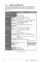
...) SSI Location #) Slot Type 1 x PCI-E x16 (Gen3 x8 link, Full-height/FL) 1 x PCI-E x16 (Gen3 x8 link, Full-height/HL) Intel® C612 10 x SATA 6 Gbps ports or Storage 9 x SATA 6 Gbps ports + 1 x discrete M.2 socket SATA Controller Intel® RSTe (for Windows only; Networking LAN Graphic VGA 2 x Intel® I210T 1 x Management LAN Aspeed AST2400 32MB 2 x Hot-swap 2.5-inch SSD Bays (continued on the next page) 1-4 Chapter 1: Product introduction 1.3 System specifications The ASUS TS700-E8-PS4, TS700-E8-RS8...
...) SSI Location #) Slot Type 1 x PCI-E x16 (Gen3 x8 link, Full-height/FL) 1 x PCI-E x16 (Gen3 x8 link, Full-height/HL) Intel® C612 10 x SATA 6 Gbps ports or Storage 9 x SATA 6 Gbps ports + 1 x discrete M.2 socket SATA Controller Intel® RSTe (for Windows only; Networking LAN Graphic VGA 2 x Intel® I210T 1 x Management LAN Aspeed AST2400 32MB 2 x Hot-swap 2.5-inch SSD Bays (continued on the next page) 1-4 Chapter 1: Product introduction 1.3 System specifications The ASUS TS700-E8-PS4, TS700-E8-RS8...
User Guide
Page 17
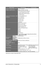
...; Server 2012 Windows® Server 2008 R2 RedHat® Enterprise Linux SuSE® Liunx Enterprise Server CentOS Unbuntu VMWare Citrix XenServer Management Solution Software Out of Band Remote Management * Support versions are subject to change without notice. ASUS TS700-E8-PS4, TS700-E8-RS8 1-5 Model Name Auxiliary Storage Device Bay (Floppy / Optical Drive) TS700-E8-PS4 3 x 5.25" media bays (Options: No Device / DVD-RW) 1 x PS/2 keyboard/mouse combo port 1 x Q-Code Logger button with LED 1 x BIOS Flashback button with LED TS700-E8-RS8 1 x S/PDIF Out port Onboard I/O Connectors...
...; Server 2012 Windows® Server 2008 R2 RedHat® Enterprise Linux SuSE® Liunx Enterprise Server CentOS Unbuntu VMWare Citrix XenServer Management Solution Software Out of Band Remote Management * Support versions are subject to change without notice. ASUS TS700-E8-PS4, TS700-E8-RS8 1-5 Model Name Auxiliary Storage Device Bay (Floppy / Optical Drive) TS700-E8-PS4 3 x 5.25" media bays (Options: No Device / DVD-RW) 1 x PS/2 keyboard/mouse combo port 1 x Q-Code Logger button with LED 1 x BIOS Flashback button with LED TS700-E8-RS8 1 x S/PDIF Out port Onboard I/O Connectors...

User Guide
Page 18
Upgrade the optional PIKE card before using eight hot-swap 3.5-inch HDDs. 1.4 Front panel features Message LED HDD access LED Power LED Optical drive (optional) 2 x Empty 5.25-inch bays 1 2 4-bay HDD module (First set*) 4-bay HDD module (Second set, TS700-E8-RS8 only**) LAN1 LED LAN2 LED Location LED (Reserved) Security lock Power button Reset button USB BIOS Flashback SPDIF OUT Management USB3.0 USB3.0 side rear c/sub MIC IN LINE OUT LINE IN KY Q-Code Logger Headphone jack Microphone jack 2 x USB 2.0 ports 2 x USB 3.0 ports • Refer...
Upgrade the optional PIKE card before using eight hot-swap 3.5-inch HDDs. 1.4 Front panel features Message LED HDD access LED Power LED Optical drive (optional) 2 x Empty 5.25-inch bays 1 2 4-bay HDD module (First set*) 4-bay HDD module (Second set, TS700-E8-RS8 only**) LAN1 LED LAN2 LED Location LED (Reserved) Security lock Power button Reset button USB BIOS Flashback SPDIF OUT Management USB3.0 USB3.0 side rear c/sub MIC IN LINE OUT LINE IN KY Q-Code Logger Headphone jack Microphone jack 2 x USB 2.0 ports 2 x USB 3.0 ports • Refer...

User Guide
Page 21
Chassis intrusion switch 5. Connect a USB floppy disk drive to any system component. ASUS Z10PE-D16 WS Server Board 4. TS700-E8-PS4 only supports this set) 9. 4-bay HDD module (Second set with backplane, TS700-E8-RS8 only) 10. 2 x 80mm x 38mm system fans (hidden beside the backplane) 11. 2 x 2.5-inch SSD bays (TS700-E8-RS8 only) Turn off the system power and detach the power supply before removing or replacing any of the USB ports on the front or rear panel if you need to use a floppy disk. *WARNING HAZARDOUS...
Chassis intrusion switch 5. Connect a USB floppy disk drive to any system component. ASUS Z10PE-D16 WS Server Board 4. TS700-E8-PS4 only supports this set) 9. 4-bay HDD module (Second set with backplane, TS700-E8-RS8 only) 10. 2 x 80mm x 38mm system fans (hidden beside the backplane) 11. 2 x 2.5-inch SSD bays (TS700-E8-RS8 only) Turn off the system power and detach the power supply before removing or replacing any of the USB ports on the front or rear panel if you need to use a floppy disk. *WARNING HAZARDOUS...
User Guide
Page 45
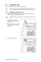
... documentation that came with it and make the necessary hardware settings for the card. TS700-E8-RS8 supports only one GPU card. 2. Release the screws on a flat, stable surface. 3. TS700-E8-PS4 supports up to install the expansion card. 4. ASUS TS700-E8-PS4, TS700-E8-RS8 2-21 Ensure to the motherboard and other system components! 2.7.1 Installing an expansion card 1. 2.7 Expansion slots Remove the metal slot cover before installing or removing expansion cards. Remove the side chassis cover. Failure to do so may cause severe damage to unplug the power...
... documentation that came with it and make the necessary hardware settings for the card. TS700-E8-RS8 supports only one GPU card. 2. Release the screws on a flat, stable surface. 3. TS700-E8-PS4 supports up to install the expansion card. 4. ASUS TS700-E8-PS4, TS700-E8-RS8 2-21 Ensure to the motherboard and other system components! 2.7.1 Installing an expansion card 1. 2.7 Expansion slots Remove the metal slot cover before installing or removing expansion cards. Remove the side chassis cover. Failure to do so may cause severe damage to unplug the power...
User Guide
Page 47
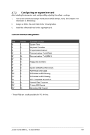
Install the software drivers for PCI devices. ASUS TS700-E8-PS4, TS700-E8-RS8 2-23 Standard Interrupt assignments IRQ Priority Standard function 0 1 System Timer 1 2 Keyboard Controller 2 - 2.7.2 Configuring an expansion card After installing the expansion card, configure it by adjusting the software settings. 1. Assign an IRQ to the following tables. 3. Turn on BIOS setup. 2. Refer to the card. Programmable Interrupt 3* 11 Communications Port (COM2) 4* 12 Communications Port (COM1) 5* 13 -- 6 14 Floppy Disk Controller 7* 15 -- 8 3 System CMOS/...
Install the software drivers for PCI devices. ASUS TS700-E8-PS4, TS700-E8-RS8 2-23 Standard Interrupt assignments IRQ Priority Standard function 0 1 System Timer 1 2 Keyboard Controller 2 - 2.7.2 Configuring an expansion card After installing the expansion card, configure it by adjusting the software settings. 1. Assign an IRQ to the following tables. 3. Turn on BIOS setup. 2. Refer to the card. Programmable Interrupt 3* 11 Communications Port (COM2) 4* 12 Communications Port (COM1) 5* 13 -- 6 14 Floppy Disk Controller 7* 15 -- 8 3 System CMOS/...
User Guide
Page 51
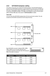
... determine their counterpart connectors at the back side of the SATA/SAS backplane faces the front panel when installed. See section 1.7 LED information for the hot-swap drive trays. The backplane design incorporates a hot-swap feature to indicate HDD status. The LEDs on the backplane connect to the front panel LEDs to allow easy connection or removal of SATA/SAS hard disks. Refer to support Serial ATA hard disk drives and SAS hard disk drives. The SATA/SAS backplane has four 22-pin SATA/SAS connectors to the...
... determine their counterpart connectors at the back side of the SATA/SAS backplane faces the front panel when installed. See section 1.7 LED information for the hot-swap drive trays. The backplane design incorporates a hot-swap feature to indicate HDD status. The LEDs on the backplane connect to the front panel LEDs to allow easy connection or removal of SATA/SAS hard disks. Refer to support Serial ATA hard disk drives and SAS hard disk drives. The SATA/SAS backplane has four 22-pin SATA/SAS connectors to the...

User Guide
Page 71
... Console Input Devices are not available PCI resource allocation error. System has transitioned into ACPI mode. ASUS TS700-E8-PS4, TS700-E8-RS8 4-11 BF D0 D1 D2 D3 D4 D5 D6 D7 D8 D9 DA DB DC Description Reserved for ASL (see ASL Status Codes section below) Ready To Boot event Legacy Boot event Exit Boot Services event Runtime Set Virtual Address MAP Begin Runtime Set Virtual Address MAP End Legacy Option ROM Initialization System Reset USB hot plug PCI bus hot...
... Console Input Devices are not available PCI resource allocation error. System has transitioned into ACPI mode. ASUS TS700-E8-PS4, TS700-E8-RS8 4-11 BF D0 D1 D2 D3 D4 D5 D6 D7 D8 D9 DA DB DC Description Reserved for ASL (see ASL Status Codes section below) Ready To Boot event Legacy Boot event Exit Boot Services event Runtime Set Virtual Address MAP Begin Runtime Set Virtual Address MAP End Legacy Option ROM Initialization System Reset USB hot plug PCI bus hot...

User Guide
Page 131
... options: [Disabled] [Enabled] ASUS TS700-E8-PS4, TS700-E8-RS8 5-43 Configuration options: [Disabled] [Enabled] Memory Error Enabling Memory corrected Error enabling [Disabled] This item allows you to enable or disable the WHEA support. Configuration options: [Disabled] [Enabled] Whea Settings Whea Support [Enabled] This item allows you to enable or disable the S/W Error Injection support. 5.6.9 Server ME Configuration Displays the Server ME Technology parameters on your system. 5.6.10 Runtime Error Logging Support Runtime Error Logging S/W Error Injection Support [Disabled] This...
... options: [Disabled] [Enabled] ASUS TS700-E8-PS4, TS700-E8-RS8 5-43 Configuration options: [Disabled] [Enabled] Memory Error Enabling Memory corrected Error enabling [Disabled] This item allows you to enable or disable the WHEA support. Configuration options: [Disabled] [Enabled] Whea Settings Whea Support [Enabled] This item allows you to enable or disable the S/W Error Injection support. 5.6.9 Server ME Configuration Displays the Server ME Technology parameters on your system. 5.6.10 Runtime Error Logging Support Runtime Error Logging S/W Error Injection Support [Disabled] This...

User Guide
Page 132
... minutes] Allows you to enable or disable Serial Mux configuration. 5.7 Server Mgmt menu The Server Management menu displays the server management status and allows you to configure the how the system should respond if the OS Boot Watch Timer expires. Configuration options: [5 minutes] [10 minutes] [15 minutes] [20 minutes] OS Wtd Timer Policy [Reset] This item allows you to change the settings. OS Watchdog Timer [Disabled] This item allows you...
... minutes] Allows you to enable or disable Serial Mux configuration. 5.7 Server Mgmt menu The Server Management menu displays the server management status and allows you to configure the how the system should respond if the OS Boot Watch Timer expires. Configuration options: [5 minutes] [10 minutes] [15 minutes] [20 minutes] OS Wtd Timer Policy [Reset] This item allows you to change the settings. OS Watchdog Timer [Disabled] This item allows you...

User Guide
Page 148
.... With the RAID 10 configuration you install an operating system to the selected hard disk drive. • Please refer to chapter 2 for how to select the RAID configuration utility. Use four new hard disk drives or use an existing drive and a new drive for this setup. 6.1 Setting up RAID The motherboard supports the following SATA RAID solutions: • LSI MegaRAID software RAID Configuration Utility with RAID 0, RAID 1, RAID 10, and RAID 5 support (for Windows OS only). 6.1.1 RAID definitions RAID 0 (Data striping) optimizes two identical hard disk drives to read and...
.... With the RAID 10 configuration you install an operating system to the selected hard disk drive. • Please refer to chapter 2 for how to select the RAID configuration utility. Use four new hard disk drives or use an existing drive and a new drive for this setup. 6.1 Setting up RAID The motherboard supports the following SATA RAID solutions: • LSI MegaRAID software RAID Configuration Utility with RAID 0, RAID 1, RAID 10, and RAID 5 support (for Windows OS only). 6.1.1 RAID definitions RAID 0 (Data striping) optimizes two identical hard disk drives to read and...

User Guide
Page 149
... the power connector on each drive and to save your changes and exit the BIOS Setup. Connect a SATA power cable to use the RAID configuration utility. Enter the BIOS Setup during POST. 2. Press to the SATA connector on the Serial ATA connectors supported by Intel® C612 chipset. Connect a SATA signal cable to the signal connector at the back of the same model and capacity when creating a disk array. For example, use , you can create a RAID set using the utilities embedded in the system user guide. 2. ASUS TS700-E8-PS4, TS700-E8...
... the power connector on each drive and to save your changes and exit the BIOS Setup. Connect a SATA power cable to use the RAID configuration utility. Enter the BIOS Setup during POST. 2. Press to the SATA connector on the Serial ATA connectors supported by Intel® C612 chipset. Connect a SATA signal cable to the signal connector at the back of the same model and capacity when creating a disk array. For example, use , you can create a RAID set using the utilities embedded in the system user guide. 2. ASUS TS700-E8-PS4, TS700-E8...

User Guide
Page 150
...09231523R Management Menu Configure Initialize Objects Rebuild Check Consistency Configure VD(s) Use Cursor Keys to enter the utility. During POST, the LSI MegaRAID software RAID configuration utility automatically detects the installed SATA hard disk drives and displays any existing RAID set (s) from SATA hard disk drives connected to the SATA connectors supported by the motherboard southbridge chip. The keys on the legend box allow you create RAID sets with the LSI MegaRAID software RAID configuration utility, the boot priority of the screen is enabled. • The RAID setup screens...
...09231523R Management Menu Configure Initialize Objects Rebuild Check Consistency Configure VD(s) Use Cursor Keys to enter the utility. During POST, the LSI MegaRAID software RAID configuration utility automatically detects the installed SATA hard disk drives and displays any existing RAID set (s) from SATA hard disk drives connected to the SATA connectors supported by the motherboard southbridge chip. The keys on the legend box allow you create RAID sets with the LSI MegaRAID software RAID configuration utility, the boot priority of the screen is enabled. • The RAID setup screens...

User Guide
Page 152
... drive indicator changes from READY to the SATA ports. Press to configure array setting. 4. LSI Software RAID Configuration Utility Ver C.05 Sep 17,2010 BIOS Version A.10.09231523R Easy Configuration - ARRAY SELECTION MENU Management Menu Configure PORT # Initialize Objects 0 ONLIN A00-00 Rebuild 1 ONLIN A00-01 Check Consistency 2 READY 3 READY Port # 2 DISK 74.74GB HDS728080PLA380 05.01C05 SPACE-Sel,ENTER-EndArray,F10-Configure,F2-Drive Info,F3-Virtual Drives,F4-HSP • The information of the selected hard disk drive displays...
... drive indicator changes from READY to the SATA ports. Press to configure array setting. 4. LSI Software RAID Configuration Utility Ver C.05 Sep 17,2010 BIOS Version A.10.09231523R Easy Configuration - ARRAY SELECTION MENU Management Menu Configure PORT # Initialize Objects 0 ONLIN A00-00 Rebuild 1 ONLIN A00-01 Check Consistency 2 READY 3 READY Port # 2 DISK 74.74GB HDS728080PLA380 05.01C05 SPACE-Sel,ENTER-EndArray,F10-Configure,F2-Drive Info,F3-Virtual Drives,F4-HSP • The information of the selected hard disk drive displays...

User Guide
Page 157
... To add a new RAID configuration: 1. Select the drive(s) you want to the SATA ports. ASUS TS700-E8-PS4, TS700-E8-RS8 6-11 LSI Software RAID Configuration Utility Ver C.05 Sep 17,2010 BIOS Version A.10.09231523R Configuration Menu Easy Configuration Management MenuNew Configuration Configure View/Add Configuration Initialize Clear Configuration Objects Select Boot Drive Rebuild Check Consistency View/Add to ONLIN A[X]-[Y], where X is the array number, and Y is the drive number. When selected, the drive indicator changes from READY to The Existing Configuration Use Cursor...
... To add a new RAID configuration: 1. Select the drive(s) you want to the SATA ports. ASUS TS700-E8-PS4, TS700-E8-RS8 6-11 LSI Software RAID Configuration Utility Ver C.05 Sep 17,2010 BIOS Version A.10.09231523R Configuration Menu Easy Configuration Management MenuNew Configuration Configure View/Add Configuration Initialize Clear Configuration Objects Select Boot Drive Rebuild Check Consistency View/Add to ONLIN A[X]-[Y], where X is the array number, and Y is the drive number. When selected, the drive indicator changes from READY to The Existing Configuration Use Cursor...

User Guide
Page 160
...Physical Drive Objects Rebuild Check Consistency Virtual Drive(1) Virtual Drive 0 Select VD Press ENTER To Select A VD, To Delete A VD 6-14 Chapter 6: RAID configuration From the Management Menu, select Objects > Virtual Drive, and then press . Using the Objects command To initialize the virtual drives using the Objects command 1. LSI Software RAID Configuration Utility Ver C.05 Sep 17,2010 BIOS Version A.10.09231523R Objects Management MAednaupter Configure Virtual Drive Initialize Physical Drive Objects Rebuild Check Consistency Change VD Parameters Use Cursor Keys To...
...Physical Drive Objects Rebuild Check Consistency Virtual Drive(1) Virtual Drive 0 Select VD Press ENTER To Select A VD, To Delete A VD 6-14 Chapter 6: RAID configuration From the Management Menu, select Objects > Virtual Drive, and then press . Using the Objects command To initialize the virtual drives using the Objects command 1. LSI Software RAID Configuration Utility Ver C.05 Sep 17,2010 BIOS Version A.10.09231523R Objects Management MAednaupter Configure Virtual Drive Initialize Physical Drive Objects Rebuild Check Consistency Change VD Parameters Use Cursor Keys To...

User Guide
Page 188
... finishes loading the RAID driver, replace the motherboard Support DVD with the OS installation. Select the drive to continue. 7-4 Chapter 7: Driver installation A message appears, reminding you need from the list and click Next. 7. Locate the driver in your system, eject the Windows OS installation disc and replace with the motherboard Support DVD into the optical drive. Setup then proceeds with the Windows Server installation disc. Follow screen instructions to install Windows and click Next. 8. Select the RAID controller driver you to...
... finishes loading the RAID driver, replace the motherboard Support DVD with the OS installation. Select the drive to continue. 7-4 Chapter 7: Driver installation A message appears, reminding you need from the list and click Next. 7. Locate the driver in your system, eject the Windows OS installation disc and replace with the motherboard Support DVD into the optical drive. Setup then proceeds with the Windows Server installation disc. Follow screen instructions to install Windows and click Next. 8. Select the RAID controller driver you to...

User Guide
Page 197
.... By default, the Drivers menu is displayed on software and utilities. 2. Install the necessary drivers to run the support DVD. The support DVD is supported on Windows® Server 2008 R2, Windows® Server 2012, and Windows® Server 2012 R2. 7.3 Running the Support DVD When you can install to maximize the features of your computer, browse the contents of the support DVD to change at any time without notice. If Autorun is enabled in your motherboard. 1. ASUS TS700-E8-PS4, TS700-E8-RS8 7-13...
.... By default, the Drivers menu is displayed on software and utilities. 2. Install the necessary drivers to run the support DVD. The support DVD is supported on Windows® Server 2008 R2, Windows® Server 2012, and Windows® Server 2012 R2. 7.3 Running the Support DVD When you can install to maximize the features of your computer, browse the contents of the support DVD to change at any time without notice. If Autorun is enabled in your motherboard. 1. ASUS TS700-E8-PS4, TS700-E8-RS8 7-13...


