User Manual
Page 13
... ASUS TS100-E10-PI4 is SATA 6Gb/s only. SAS Controller Optional: ASUS PIKE II 3008-8i 8-port SAS 12G RAID card 3 x Internal 3.5" (or 2 x 2.5" optional cage) drive bays* I = internal 1 x Internal 2.5" drive bay A or S will be hot- 1 x Optional internal 5.25" to ASUS ...and Intel® 8th/9th Generation Core™ i3 Processors. Model Name Processor Support Core Logic Total Slots TS100-E10-PI4 1 x Socket LGA1151 Intel® Xeon® processor E-21xx/E-22xx product family Intel® 8th/9th Generation... / DVD-RW / DVD ROM (continued on the next page) ASUS TS100-E10-PI4 1-3
... ASUS TS100-E10-PI4 is SATA 6Gb/s only. SAS Controller Optional: ASUS PIKE II 3008-8i 8-port SAS 12G RAID card 3 x Internal 3.5" (or 2 x 2.5" optional cage) drive bays* I = internal 1 x Internal 2.5" drive bay A or S will be hot- 1 x Optional internal 5.25" to ASUS ...and Intel® 8th/9th Generation Core™ i3 Processors. Model Name Processor Support Core Logic Total Slots TS100-E10-PI4 1 x Socket LGA1151 Intel® Xeon® processor E-21xx/E-22xx product family Intel® 8th/9th Generation... / DVD-RW / DVD ROM (continued on the next page) ASUS TS100-E10-PI4 1-3

User Manual
Page 15
The power and reset buttons, LED indicators, optical drive, and USB ports are all conveniently located at the front panel for the LED descriptions. Optical Drive (Optional) Empty 5.25-inch bay Card reader (optional) USB 3.0 ports USB 2.0 ports Headphone port Microphone port Smart Card SD/MMC/MS Power LED Reset button Power button HDD access LED Refer to the Front panel LEDs section for easy access. ASUS TS100-E10-PI4 1-5 1.4 Front panel features The TS100-E10-PI4 Pedestal server features a simple yet stylish front panel design.
The power and reset buttons, LED indicators, optical drive, and USB ports are all conveniently located at the front panel for the LED descriptions. Optical Drive (Optional) Empty 5.25-inch bay Card reader (optional) USB 3.0 ports USB 2.0 ports Headphone port Microphone port Smart Card SD/MMC/MS Power LED Reset button Power button HDD access LED Refer to the Front panel LEDs section for easy access. ASUS TS100-E10-PI4 1-5 1.4 Front panel features The TS100-E10-PI4 Pedestal server features a simple yet stylish front panel design.

User Manual
Page 17
... disk, connect the USB floppy disk drive to any system component. Expansion card locks 5. WARNING HAZARDOUS MOVING PARTS KEEP FINGERS AND OTHER BODY PARTS AWAY ASUS TS100-E10-PI4 1-7 Optical drive (Optional) 6. 1 x 5.25-inch drive bay 7. The barebone server does not include a floppy disk drive. Power supply unit 2. 120 mm x 120 mm system fan...
... disk, connect the USB floppy disk drive to any system component. Expansion card locks 5. WARNING HAZARDOUS MOVING PARTS KEEP FINGERS AND OTHER BODY PARTS AWAY ASUS TS100-E10-PI4 1-7 Optical drive (Optional) 6. 1 x 5.25-inch drive bay 7. The barebone server does not include a floppy disk drive. Power supply unit 2. 120 mm x 120 mm system fan...

User Manual
Page 19
It includes description of the jumpers and connectors on the motherboard. 2 ASUS TS100-E10-PI4 2-1 Chapter 2: Hardware Information Hardware Information This chapter lists the hardware setup procedures that you have to perform when installing system components.
It includes description of the jumpers and connectors on the motherboard. 2 ASUS TS100-E10-PI4 2-1 Chapter 2: Hardware Information Hardware Information This chapter lists the hardware setup procedures that you have to perform when installing system components.

User Manual
Page 21
Slightly pull the side cover toward the rear just enough to detach it aside. ASUS TS100-E10-PI4 2-3 Remove the cover and set it from the chassis. 4. 3.
Slightly pull the side cover toward the rear just enough to detach it aside. ASUS TS100-E10-PI4 2-3 Remove the cover and set it from the chassis. 4. 3.

User Manual
Page 23
... pins on the bottom-left corner of the socket. 3. The CPU fits in only one orientation. Gold triangle mark Alignment key CPU notches Alignment key ASUS TS100-E10-PI4 2-5 Lift the load lever until it to the socket's alignment keys. 2. Load lever Retention tab Load plate 4. Press the load lever with your thumb (A), then...
... pins on the bottom-left corner of the socket. 3. The CPU fits in only one orientation. Gold triangle mark Alignment key CPU notches Alignment key ASUS TS100-E10-PI4 2-5 Lift the load lever until it to the socket's alignment keys. 2. Load lever Retention tab Load plate 4. Press the load lever with your thumb (A), then...

User Manual
Page 25
2.2.2 Installing the CPU heatsink and fan assembly To install the CPU heatsink and fan assembly ASUS TS100-E10-PI4 2-7
2.2.2 Installing the CPU heatsink and fan assembly To install the CPU heatsink and fan assembly ASUS TS100-E10-PI4 2-7
User Manual
Page 27
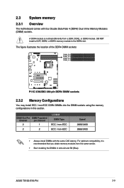
... in slots A2 and B2 (Blue). For optimum compatibility, it is notched differently from the same vendor. • Start installing the DIMMs in this section. ASUS TS100-E10-PI4 2-9 A DDR4 module is recommended that you obtain memory modules from a DDR, DDR2, or DDR3 module. DIMM Slot Per DIMM Populated Channel per Channel 2 1 2 2 UDIMM DIMM...
... in slots A2 and B2 (Blue). For optimum compatibility, it is notched differently from the same vendor. • Start installing the DIMMs in this section. ASUS TS100-E10-PI4 2-9 A DDR4 module is recommended that you obtain memory modules from a DDR, DDR2, or DDR3 module. DIMM Slot Per DIMM Populated Channel per Channel 2 1 2 2 UDIMM DIMM...
User Manual
Page 29
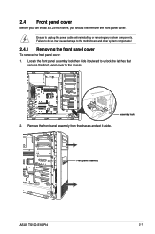
... panel assembly from the chassis and set it outward to unlock the latches that secures the front panel cover to the chassis. Front panel assembly ASUS TS100-E10-PI4 2-11 assembly lock 2. 2.4 Front panel cover Before you can install a 5.25-inch drive, you should first remove the front panel cover. Locate the front panel...
... panel assembly from the chassis and set it outward to unlock the latches that secures the front panel cover to the chassis. Front panel assembly ASUS TS100-E10-PI4 2-11 assembly lock 2. 2.4 Front panel cover Before you can install a 5.25-inch drive, you should first remove the front panel cover. Locate the front panel...

User Manual
Page 31
Prepare the 5.25-inch drive. 5. bay locks 7. Insert and carefully push the drive into the bay until its screw holes align with the holes on the bay. 6. Connect the SATA cable to the SATA connector of the drive. 9. 4. Reinstall the front panel cover. SATA power cable SATA cable ASUS TS100-E10-PI4 2-13 Connect a SATA power cable from the power supply to secure the drive in place. Push the bay locks to the power connector of the drive. 8.
Prepare the 5.25-inch drive. 5. bay locks 7. Insert and carefully push the drive into the bay until its screw holes align with the holes on the bay. 6. Connect the SATA cable to the SATA connector of the drive. 9. 4. Reinstall the front panel cover. SATA power cable SATA cable ASUS TS100-E10-PI4 2-13 Connect a SATA power cable from the power supply to secure the drive in place. Push the bay locks to the power connector of the drive. 8.

User Manual
Page 33
5. ASUS TS100-E10-PI4 2-15 Connect the SATA cable and SATA power cable to the HDD cage using the bundled set of screws. 6. Secure the 3.5-inch HDD to the 3.5-inch HDD. Swing the HDD cage inwards until it clicks back into place. 7.
5. ASUS TS100-E10-PI4 2-15 Connect the SATA cable and SATA power cable to the HDD cage using the bundled set of screws. 6. Secure the 3.5-inch HDD to the 3.5-inch HDD. Swing the HDD cage inwards until it clicks back into place. 7.

User Manual
Page 35
ASUS TS100-E10-PI4 2-17 Connect a SATA cable and a SATA power cable to the HDD cage using the bundled set of screws. 7. Secure the 2.5-inch HDD/SSD to the 2.5-inch HDD/SSD. Swing the HDD cage inwards until it clicks back into place. 8. 6.
ASUS TS100-E10-PI4 2-17 Connect a SATA cable and a SATA power cable to the HDD cage using the bundled set of screws. 7. Secure the 2.5-inch HDD/SSD to the 2.5-inch HDD/SSD. Swing the HDD cage inwards until it clicks back into place. 8. 6.

User Manual
Page 37
Align and insert the expansion card into place securing the expansion card to the chassis. 6. (Optional) Replace the screw of the metal bracket. PCI-E latch ASUS TS100-E10-PI4 2-19 Lift the PCI-E latch inwards until it clicks into the PCI-E slot. Expansion card PCI-E slot 5. 4.
Align and insert the expansion card into place securing the expansion card to the chassis. 6. (Optional) Replace the screw of the metal bracket. PCI-E latch ASUS TS100-E10-PI4 2-19 Lift the PCI-E latch inwards until it clicks into the PCI-E slot. Expansion card PCI-E slot 5. 4.

User Manual
Page 39
... order if you need to install or remove previously installed or new system components, or when the system fan needs to reinstall the system fan. ASUS TS100-E10-PI4 2-21 Disconnect the system fan cable from the REAR_FAN1 connector on the motherboard. 2. To remove the system fan: 1. Remove the system fan. Keep the screws...
... order if you need to install or remove previously installed or new system components, or when the system fan needs to reinstall the system fan. ASUS TS100-E10-PI4 2-21 Disconnect the system fan cable from the REAR_FAN1 connector on the motherboard. 2. To remove the system fan: 1. Remove the system fan. Keep the screws...

User Manual
Page 43
... (10-1 pin COM1) 21. VGA controller setting (3-pin VGA_SW1) Page 3-13 3-12 2-9 2-4 3-17 3-7 3-6 3-11 3-6 3-9 3-15 3-14 3-11 3-10 3-10 3-17 3-9 3-4 3-18 3-12 3-18 3-19 3-16 3-5 3-5 ASUS TS100-E10-PI4 3-3 Layout contents Internal connectors / Sockets / Jumpers / LEDs 1. ATX power connectors (24-pin EATXPWR1; 8-pin EATX12V1) 2. CPU, front, and rear fan connectors (4-pin FRNT_FAN1-4; USB 2.0 connectors...
... (10-1 pin COM1) 21. VGA controller setting (3-pin VGA_SW1) Page 3-13 3-12 2-9 2-4 3-17 3-7 3-6 3-11 3-6 3-9 3-15 3-14 3-11 3-10 3-10 3-17 3-9 3-4 3-18 3-12 3-18 3-19 3-16 3-5 3-5 ASUS TS100-E10-PI4 3-3 Layout contents Internal connectors / Sockets / Jumpers / LEDs 1. ATX power connectors (24-pin EATXPWR1; 8-pin EATX12V1) 2. CPU, front, and rear fan connectors (4-pin FRNT_FAN1-4; USB 2.0 connectors...

User Manual
Page 45
Set to pins 1-2 to activate the Gigabit LAN feature. Set to pins 1-2 to activate the VGA feature. 3. LAN controller setting (3-pin LAN_SW1) This jumper allows you to enable or disable the onboard LAN_SW1. VGA controller setting (3-pin VGA_SW1) This jumper allows you to enable or disable the onboard VGA controller. ASUS TS100-E10-PI4 3-5 2.
Set to pins 1-2 to activate the Gigabit LAN feature. Set to pins 1-2 to activate the VGA feature. 3. LAN controller setting (3-pin LAN_SW1) This jumper allows you to enable or disable the onboard LAN_SW1. VGA controller setting (3-pin VGA_SW1) This jumper allows you to enable or disable the onboard VGA controller. ASUS TS100-E10-PI4 3-5 2.

User Manual
Page 47
ASUS TS100-E10-PI4 3-7 The green LED lights up to indicate that the system is a reminder that you to update the BIOS ME block. 3.3 Onboard LEDs 1. The illustration below shows the location of the onboard LED. This is ON, in sleep mode, or in any motherboard component. Standby Power LED (SBPWR1) The motherboard comes with a standby power LED. PCH_MFG1 setting (3-pin PCH_MFG1) This jumper allows you should shut down the system and unplug the power cable before removing or plugging in soft-off mode. 6.
ASUS TS100-E10-PI4 3-7 The green LED lights up to indicate that the system is a reminder that you to update the BIOS ME block. 3.3 Onboard LEDs 1. The illustration below shows the location of the onboard LED. This is ON, in sleep mode, or in any motherboard component. Standby Power LED (SBPWR1) The motherboard comes with a standby power LED. PCH_MFG1 setting (3-pin PCH_MFG1) This jumper allows you should shut down the system and unplug the power cable before removing or plugging in soft-off mode. 6.
User Manual
Page 49
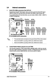
ASUS TS100-E10-PI4 3-9 Trusted Platform Module connector (14-1 pin TPM1) This connector supports a TPM (Trusted Platform Module) system, which can create a RAID 0, RAID 1, RAID 10, or RAID 5 configuration. &#...
ASUS TS100-E10-PI4 3-9 Trusted Platform Module connector (14-1 pin TPM1) This connector supports a TPM (Trusted Platform Module) system, which can create a RAID 0, RAID 1, RAID 10, or RAID 5 configuration. &#...

User Manual
Page 51
..., and general purpose data. Serial General Purpose Input/Output connector (6-1 pin SGPIO1) The SGPIO 1 connector is used for additional USB 3.0 front or rear panel ports. 5. ASUS TS100-E10-PI4 3-11 With an installed USB 3.0 module, you to 5 Gbps, faster charging time for USB-chargeable devices, optimized power efficiency, and backward compatibility with USB 2.0. 6.
..., and general purpose data. Serial General Purpose Input/Output connector (6-1 pin SGPIO1) The SGPIO 1 connector is used for additional USB 3.0 front or rear panel ports. 5. ASUS TS100-E10-PI4 3-11 With an installed USB 3.0 module, you to 5 Gbps, faster charging time for USB-chargeable devices, optimized power efficiency, and backward compatibility with USB 2.0. 6.

User Manual
Page 53
.... • This motherboard supports ATX2.0 PSU or later version. • Ensure that your PSU can provide at least the minimum power required by your system. ASUS TS100-E10-PI4 3-13 The power supply plugs are for the ATX power supply plugs. Find the proper orientation and push down firmly until the connectors completely fit...
.... • This motherboard supports ATX2.0 PSU or later version. • Ensure that your PSU can provide at least the minimum power required by your system. ASUS TS100-E10-PI4 3-13 The power supply plugs are for the ATX power supply plugs. Find the proper orientation and push down firmly until the connectors completely fit...


